Thingiverse
Insteon In-LineLinc Mount for 4" Square Electrical Junction Box by joshuanapoli
by Thingiverse
Last crawled date: 3 years ago
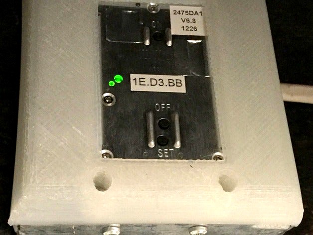
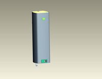
Insteon In-LineLinc Dimmers are good for controlling built-in lighting in my home, but their installation leaves something to be desired. The device must be associated with another device (such as a light switch) using its SET button. But once the device is installed in an electrical box, the button is not available. The large size of the device can also make it hard to get a large enough junction box.
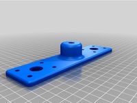
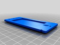
This bracket and cover are used to mount an 70x45x24mm In-LineLinc device in a 4" square electrical junction box. The cover has a window, so that the buttons can be safely accessed, without opening the electrical box. The cover extends the box by 15mm, holding the device mostly outside of the original electrical box volume. This makes it easier to pack the electrical box.
Materials
Taulman Alloy 910 works well for these parts. It holds self tapping plastic screws well. It is less flammable than ABS (UL 94 V2). Note that this cover will nevertheless be more flammable and have a lower melting temperature than a commercial UL-listed cover.
4" electrical box
8 screws: 6-19 x 0.500" or M3.63 x 12mm Pan Head Thread Forming Screw for Plastics. McMaster 99512A259 or 99397A682.
Tools
Drill
Torx T15 driver.
Right-angle ratcheting driver with T15 tip is useful depending on how the electrical box is mounted.
1/8" drill bit
17/64" drill bit
Instructions
Measure the distance between the side mounting screw holes on your 4" box. Some boxes have 1.250", others have 1.325", and some boxes have both. Print the correct device bracket and face-plate.
Drill the eight pilot holes of the bracket with a 1/8" bit. If necessary, clean out the screw head clearance hole on the face-plate with a 17/64" drill bit.
Mount the electrical box such that the side mount holes are accessible.
Complete all wiring within the electrical box, including the Insteon device.
Slide the Insteon device through the opening of the bracket. Use four screws to mount the bracket to the electrical box.
Position the device within the bracket and put the faceplate in place. Use four screws to secure the faceplate to the bracket.
Similar models
thingiverse
free

Full Graphic Smart Controller Case by RC_CnC
...ount lcd with the remaining 4) m3x8 button head screws.
with this design, other mounting brackets can be screwed to back of case.
thingiverse
free

Ceiling Electrical Box Cover by CampfireMike
..." diameter electrical box cover for ceiling junction boxes. the mounting holes are 2.75" apart and 0.2" diameter.
thingiverse
free
3/8" Screw Mount Bracket for StreamDeck XL by Magathery
...2171", so as to mount to an elgato "multi mount" or a 1/4" screw thread via a 1/4" to 3/8" adapter.
thingiverse
free

Insteon Mini Remote Wall Mount Bracket p/n 2444B4 by rssalerno
...version that uses 3m command strips check out my insteon mini remote screwless bracket https://www.thingiverse.com/thing:2434881.
thingiverse
free

Celestron Astromaster 114 finder scope mount by NukeSkywalker
...he secondary mirror while drilling and keep the telescope slightly raised at the primary mirror end so no metal pieces get on it.
thingiverse
free

D5SGA 'Floating' ESC Mount & Template for Mid Motor by ALPHAQGTI
...ws
use the m3x8 screws to attach the platform to the fan bracket.
use the m3x10 screws to attach the fan bracket to the bulkhead.
thingiverse
free

Ikea Lack Printer Enclosure Risers and Brackets by mcarter14777
...4" length screws use a 1/8" drill bit to pre-drill the holes in the table legs so you don't spit the particleboard.
thingiverse
free
Insteon Mini Remote Bracket for Existing Boxes! by rssalerno
...version that uses 3m command strips check out my insteon mini remote screwless bracket https://www.thingiverse.com/thing:2434881.
thingiverse
free
Electrical Bracket by Muxlo
...electrical contact mount for use in an electrical panel or junction box, can have positive on one side and negative on the other.
thingiverse
free

Azteeg X5 mini faceplate and mount by cdoe
...e ridge and 2 m3 screws.
mount has holes for m3x4x4 brass inserts but regular nylock nuts can be used instead with longer screws.
Joshuanapoli
thingiverse
free

Pipe Cap 1.25in by joshuanapoli
...iverse
this is a cap for a 1 1/4" npt threaded pipe. i used it to cap a leaky valve on the steam heating system in my home.
thingiverse
free

2in #4 rebar chair by joshuanapoli
... pieces of rebar, centered 2" above the ground. the chair keeps the rebar grid in the proper position as concrete is poured.
thingiverse
free

Thermos Foogo Base by joshuanapoli
...re how to re-glue them. so here is a printable replacement that has a snug enough snap-on fit that it will stay put without glue.
thingiverse
free

Desiccant Box with Slotted Snap on Lid, 80mm long by joshuanapoli
...ing silica gel beads. this makes it easy to tell when the desiccant is saturated. the box prints well with clear taulman t-glase.
thingiverse
free

Bosch Random Orbital Sander Dust Shroud by joshuanapoli
...he dust shroud replaces the sander's friction ring 2609170071 (http://www.ereplacementparts.com/friction-ring-p-163180.html).
Insteon
thingiverse
free

Insteon KeypadLinc 4 Button Frame by ahj3939
...insteon keypadlinc 4 button frame by ahj3939
thingiverse
4 button frame for insteon keypadlinc
thingiverse
free

Insteon Keypad KPL Button by crazeeeyez
...thingiverse
insteon 8 or 6 button (small button only) keypad model. i put a label over it so the pattern doesn't bother me.
thingiverse
free
Insteon Mini Remote Bracket for Existing Boxes! by rssalerno
...version that uses 3m command strips check out my insteon mini remote screwless bracket https://www.thingiverse.com/thing:2434881.
thingiverse
free

Insteon Hub II Wall MOUNT SKU: 2245-222 by chasenbeck
...insteon hub ii wall mount sku: 2245-222 by chasenbeck
thingiverse
just my design of insteon hub ii wall mount sku: 2245-222.
thingiverse
free

Insteon Hub II Wall MOUNT SKU: 2245-222 by chasenbeck
...insteon hub ii wall mount sku: 2245-222 by chasenbeck
thingiverse
just my design of an insteon hub ii wall mount sku: 2245-222
thingiverse
free
Insteon Mini Remote Wall Mount Bracket p/n 2444B4 by rssalerno
...version that uses 3m command strips check out my insteon mini remote screwless bracket https://www.thingiverse.com/thing:2434881.
thingiverse
free

Insteon Mini Remote Screwless Bracket by rssalerno
...style mini remote mount check out my insteon mini remote wall mount bracket p/n 2444b4 https://www.thingiverse.com/thing:2834483.
thingiverse
free

Insteon Leak Sensor Support by LincolnStout
...electrical contact to the ground. for best contact of the detectors sensor extenders there are 2 holes for zip ties to be placed.
thingiverse
free

Insteon Hub 19" 1U Rackmount Adapter by branchjoshua
...the back of the insteon hub).
the insteon hub slides in from the rear on the left side and is retained by a snap-on back bracket.
Junction
turbosquid
$30
triple junction pyramids
... available on turbo squid, the world's leading provider of digital 3d models for visualization, films, television, and games.
turbosquid
$8

Utility/Junction Box
... available on turbo squid, the world's leading provider of digital 3d models for visualization, films, television, and games.
3ddd
$1

Высокий комод Junction
...высокий комод junction
3ddd
комод
комод cd2, размер 71x51x117см
3ddd
$1
Низкий комод Junction
...низкий комод junction
3ddd
комод
комод cd2, размеры 124x50x67см
3d_ocean
$1

Road junction sign
...he object is ready to import and render in both formats. the model has been built to be able to subdivide flawlessly for a smo...
3d_export
$5

junction box - electrical
...lender and substance painter file for personal customization and tweek!<br>verts: 352<br>face: 328<br>tris: 656
turbosquid
$200

Old-Rail-Junction.3dm
... available on turbo squid, the world's leading provider of digital 3d models for visualization, films, television, and games.
turbosquid
$6

Phone junction box 4
... available on turbo squid, the world's leading provider of digital 3d models for visualization, films, television, and games.
turbosquid
$2

Junction Box (Wall Square)
... available on turbo squid, the world's leading provider of digital 3d models for visualization, films, television, and games.
turbosquid
$2

Junction Box (Floor Large)
... available on turbo squid, the world's leading provider of digital 3d models for visualization, films, television, and games.
Electrical
3d_export
$5
Electric pole
...electric pole
3dexport
electric pole for street, electricity line
3ddd
$1
electric mixer
...electric mixer
3ddd
electric mixer , миксер
electric mixer
3ddd
$1

electrical installation
...electrical installation
3ddd
electrical installation , розетка
electrical installation
turbosquid
$19
The electric water heater electric
... available on turbo squid, the world's leading provider of digital 3d models for visualization, films, television, and games.
turbosquid
free
Electrical Outlet electric splitter
... available on turbo squid, the world's leading provider of digital 3d models for visualization, films, television, and games.
3d_ocean
$20

Electric Guitar
...electric guitar
3docean
electric electric guitar guitar music music instrument
model of a electric guitar created in maya.
3d_ocean
$12

Electric Shaver
...electric shaver
3docean
electric electric shaver hair removal personal care shaver shaving
electric shaver created in 3ds max.
3ddd
$1

electrical switch
...h
3ddd
electrical , розетка
electrical switch from bticino company
series livinglight
3d_export
$7
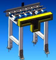
Electric Conveyor
...electric conveyor
3dexport
electric conveyor
3d_export
$5

electric drums
...electric drums
3dexport
electric drums
Square
turbosquid
free

Square
...squid
free 3d model square for download as max, obj, and stl on turbosquid: 3d models for games, architecture, videos. (1510355)
3d_export
$5

square table
...square table
3dexport
square table
turbosquid
$12

Square
...oyalty free 3d model square for download as max, obj, and fbx on turbosquid: 3d models for games, architecture, videos. (1294110)
3ddd
$1
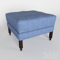
Square Ottoman
...square ottoman
3ddd
пуф
square ottoman
turbosquid
$25

The Square
...ee 3d model the square for download as mat, max, dxf, and obj on turbosquid: 3d models for games, architecture, videos. (1186399)
3d_export
$65

square
...square
3dexport
simple rendering of the scene file
3d_export
$65

square
...square
3dexport
simple rendering of the scene file
3d_export
$65

square
...square
3dexport
simple rendering of the scene file
3d_export
$65

square
...square
3dexport
simple rendering of the scene file
3d_export
$65

square
...square
3dexport
simple rendering of the scene file
Box
archibase_planet
free

Box
...box
archibase planet
box carton cardboard box
box 2 - 3d model (*.3ds) for interior 3d visualization.
archibase_planet
free

Box
...box
archibase planet
carton cardboard box box
box 1 - 3d model (*.3ds) for interior 3d visualization.
3d_export
$6
box
...box
3dexport
box
3d_export
$5
Box
...box
3dexport
box
3d_export
$5
box
...box
3dexport
box
3d_export
$5
box
...box
3dexport
box
archibase_planet
free

Box
...box
archibase planet
box box for paper notebook pencil
box - 3d model (*.gsm+*.3ds) for interior 3d visualization.
archibase_planet
free

Box
...box
archibase planet
box carton cardboard box
box n170111 - 3d model (*.gsm+*.3ds) for interior 3d visualization.
archibase_planet
free

Box
...box
archibase planet
box carton cardboard box
box n050411 - 3d model (*.gsm+*.3ds) for interior 3d visualization.
archibase_planet
free

Boxes
...boxes
archibase planet
boxes box case bin
boxes n281213 - 3d model (*.gsm+*.3ds+*.max) for interior 3d visualization.
Mount
3d_export
free

mounting bracket
...mounting plate is the portion of a hinge that attaches to the wood. mounting plates can be used indoors, cabinetry and furniture.
turbosquid
$2

MOUNTING
... available on turbo squid, the world's leading provider of digital 3d models for visualization, films, television, and games.
turbosquid
free

Mounts
... available on turbo squid, the world's leading provider of digital 3d models for visualization, films, television, and games.
turbosquid
free

Mount Fuji
...fuji
turbosquid
free 3d model mount fuji for download as obj on turbosquid: 3d models for games, architecture, videos. (1579977)
3d_export
$5

Headphone mount LR
...headphone mount lr
3dexport
headphone mount l+r
turbosquid
$39

Mount rainier
...quid
royalty free 3d model mount rainier for download as fbx on turbosquid: 3d models for games, architecture, videos. (1492586)
turbosquid
$5

pipe mounting
...quid
royalty free 3d model pipe mounting for download as obj on turbosquid: 3d models for games, architecture, videos. (1293744)
turbosquid
$3

Mounting Tires
...uid
royalty free 3d model mounting tires for download as fbx on turbosquid: 3d models for games, architecture, videos. (1708511)
3d_export
$5

Magnetic GoPro Mount
...pro mount
3dexport
cool magnetic mount for gopro. allows you to mount the camera on flat metal surfaces and get exclusive shots.
turbosquid
$5

Stone Mount
...ty free 3d model stone mount for download as ma, obj, and fbx on turbosquid: 3d models for games, architecture, videos. (1370306)
4
turbosquid
$9

Office Chair 4-4
... available on turbo squid, the world's leading provider of digital 3d models for visualization, films, television, and games.
3d_export
$5

doors- 4
...doors- 4
3dexport
doors 4
3d_export
$5

hinge 4
...hinge 4
3dexport
hinge 4
3ddd
$1

Штора №4
...штора №4
3ddd
штора №4
3d_export
free

playstation 4
...playstation 4
3dexport
playstation 4
turbosquid
$1

re 4-4 electric locomotive
... free 3d model re 4 4 electric locomotive for download as obj on turbosquid: 3d models for games, architecture, videos. (1707845)
3ddd
$1

nexus 4
...nexus 4
3ddd
lg , телефон
nexus 4
3ddd
$1
4 Poufs
...4 poufs
3ddd
пуф
4 soft poufs
turbosquid
$12

Calligraphic Digit 4 Number 4
...hic digit 4 number 4 for download as max, obj, fbx, and blend on turbosquid: 3d models for games, architecture, videos. (1389332)
3ddd
$1
Dauphin 4+
...dauphin 4+
3ddd
кресло
dauphin 4+ конференц кресло