GrabCAD
Inflatable Rigidized Heliostat
by GrabCAD
Last crawled date: 1 year, 11 months ago
Footprint when stowed: ~ 1 meter long, 1.2 meter wide, 0.5 meter in height
Reflective area: ~ 11 m2
Solar area: ~ 1,2 m2
Mass: Inflatable heliostat ~ 5 kg, supportive structure + solar, 10 kg, movement mechanism 20 kg for a total of 35 kg.
Low CoM (Centre of Mass) allows for more flexibility in rover design, without compromising stability in steep slopes and extreme angles.
For further detail please see below:
Please excuse the low quality CAD, severe software issues meant I was unable to do what I wanted in time, I hope it is adequate for the concept to be understood.
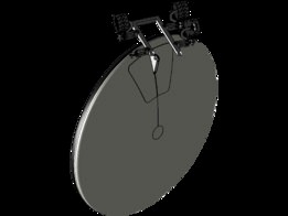
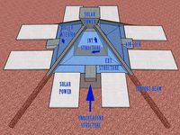
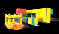
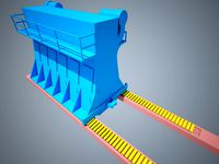
In order to minimize mass, failure modes and complexity an inflatable rigidized structure is proposed. The inflatable heliostat would be constructed in a similar way to what was proposed in the QUASAT program [QUASAT program: The ESA reflectorm G.G Reibaldi, M.C Bernasconi] just as tested and suggested in that study the structure would include resin filled ribs that would harden (by heat or UV) and rigidize the structure after deployment, thus the system would not be sensitive to degradation of the mylar film causing a leak. A typical issue with this type of system is keeping a high accuracy shape [Deployable Tensegrity Structures for Space Applications, Gunnar Tibert], for the application of a heliostat this should not be an issue, since the shape stability requirements are substantially lower in comparison to an antenna. This type of structure has the advantages of high deployment reliability, low mass and ability to be tested on earth, using a helium mixture to simulate moon-gravity. Themass per area can be estimated to be 0.421 kg/m2 (including a 10% contingency) according to the QUASAT study. This would suggest a mass of approximately 4.8 kg for the 2 m diameter inflatable proposed. The viability of the suggested mounting position is demonstrated by the deployment sequence presented in Fig.1, this further gives the judges a good demonstration of how such a structure might look in reality. Electrically activated chemical deposition or a pyrotechnic charge would be used to generate the gas needed for inflation.
The inflatable heliostat would however have a different layout in comparison to the demonstrated inflatable antenna in Fig.1 and would have on one side a transparent membrane, on the other a mirror membrane as demonstrated in [Construction and Optical Testing of Inflatable Membrane Mirror Using Structured Light Technique, Felipe Patiño-Jimenez, et.al].
Figure 1: Deployment sequence of an inflatable antenna [Chemically Rigidized Expandable Structures, M.C. Bernasconi]
To minimize the torque and power requirements of the drive motors, the heliostat is limited in its rotation around the horizontal axis, physical stop prevents it tipping forwards more than 45 degrees and a set of springs that assist in the initial deployment prevents it from tipping backwards more than 45 degrees (not depicted). The selection of these limits have been set based on a rough estimate on what might be reasonable considering the application of lumination in dark craters, heating of equipment, shading and the heliostats relative distance to the target.
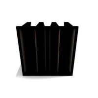
For power and sun-sensing it is suggested that the plate that carries the inflatable structure (see curved surface in the stowed state, suggested material of choice is a glass fiber sandwich panel), would also hold the solar cells and sun sensors (if using power distribution of individual solar cells is not accurate enough). With this design the solar cell efficiency is maximized (although with some losses due to the transparent film in the way) and the CoM kept low.
To orientate the inflatable structure a bevel gear design would be used around the vertical axis and a simple pinion gear design for the horizontal axis, which would be covered by MLI attached to the back of the moving solar/ inflatable support structure and the rover, completely isolating all moving parts from lunar dust, with the consequence of the heliostat not being able to rotate 360 degrees (since that would tear the MLI).
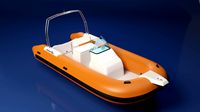
The rover design is merely a representation of a possible movable platform and the focus of the design lies in the heliostat itself. Rover wheel model is by Daniel Loera.
Reflective area: ~ 11 m2
Solar area: ~ 1,2 m2
Mass: Inflatable heliostat ~ 5 kg, supportive structure + solar, 10 kg, movement mechanism 20 kg for a total of 35 kg.
Low CoM (Centre of Mass) allows for more flexibility in rover design, without compromising stability in steep slopes and extreme angles.
For further detail please see below:
Please excuse the low quality CAD, severe software issues meant I was unable to do what I wanted in time, I hope it is adequate for the concept to be understood.
In order to minimize mass, failure modes and complexity an inflatable rigidized structure is proposed. The inflatable heliostat would be constructed in a similar way to what was proposed in the QUASAT program [QUASAT program: The ESA reflectorm G.G Reibaldi, M.C Bernasconi] just as tested and suggested in that study the structure would include resin filled ribs that would harden (by heat or UV) and rigidize the structure after deployment, thus the system would not be sensitive to degradation of the mylar film causing a leak. A typical issue with this type of system is keeping a high accuracy shape [Deployable Tensegrity Structures for Space Applications, Gunnar Tibert], for the application of a heliostat this should not be an issue, since the shape stability requirements are substantially lower in comparison to an antenna. This type of structure has the advantages of high deployment reliability, low mass and ability to be tested on earth, using a helium mixture to simulate moon-gravity. Themass per area can be estimated to be 0.421 kg/m2 (including a 10% contingency) according to the QUASAT study. This would suggest a mass of approximately 4.8 kg for the 2 m diameter inflatable proposed. The viability of the suggested mounting position is demonstrated by the deployment sequence presented in Fig.1, this further gives the judges a good demonstration of how such a structure might look in reality. Electrically activated chemical deposition or a pyrotechnic charge would be used to generate the gas needed for inflation.
The inflatable heliostat would however have a different layout in comparison to the demonstrated inflatable antenna in Fig.1 and would have on one side a transparent membrane, on the other a mirror membrane as demonstrated in [Construction and Optical Testing of Inflatable Membrane Mirror Using Structured Light Technique, Felipe Patiño-Jimenez, et.al].
Figure 1: Deployment sequence of an inflatable antenna [Chemically Rigidized Expandable Structures, M.C. Bernasconi]
To minimize the torque and power requirements of the drive motors, the heliostat is limited in its rotation around the horizontal axis, physical stop prevents it tipping forwards more than 45 degrees and a set of springs that assist in the initial deployment prevents it from tipping backwards more than 45 degrees (not depicted). The selection of these limits have been set based on a rough estimate on what might be reasonable considering the application of lumination in dark craters, heating of equipment, shading and the heliostats relative distance to the target.
For power and sun-sensing it is suggested that the plate that carries the inflatable structure (see curved surface in the stowed state, suggested material of choice is a glass fiber sandwich panel), would also hold the solar cells and sun sensors (if using power distribution of individual solar cells is not accurate enough). With this design the solar cell efficiency is maximized (although with some losses due to the transparent film in the way) and the CoM kept low.
To orientate the inflatable structure a bevel gear design would be used around the vertical axis and a simple pinion gear design for the horizontal axis, which would be covered by MLI attached to the back of the moving solar/ inflatable support structure and the rover, completely isolating all moving parts from lunar dust, with the consequence of the heliostat not being able to rotate 360 degrees (since that would tear the MLI).
The rover design is merely a representation of a possible movable platform and the focus of the design lies in the heliostat itself. Rover wheel model is by Daniel Loera.
Similar models
grabcad
free

Lunar heliostat
...all motor inside every central tube is used for reeling tape while stowing heliostat. the structure is easily scalable in height.
grabcad
free

Heliostat rover (Ijele)
...ith the necessary dimensions of about 2m by 1.5m an it is then stowed using the harness at the bottom of the primary lunar rover.
grabcad
free

🌖Torch
... m2
solar panels: 2.8 m2
heliostat mass: up to 100 kg
rover model by daniel loera (🙏)
https://grabcad.com/library/mars-rover-28
grabcad
free

PenTRAY
...m proximity.
the model has greater flexibility and solar panels which will give the heliostat to work under difficult conditions.
grabcad
free

Inflatable Heliostat
...) or (3) part mixure that would mixed during inflation.
estimated weight: 109 lbs.
estimated package volume: 17,000 cubic inches
grabcad
free

Dumbrella
...
see the infographics folder for more details. see video folder for deployment and stowing method.
suggestions are most welcome.
grabcad
free

Naja
...5 m2
solar panels: 2.8 m2
heliostat mass: up to 80 kg
rover model by daniel loera (🙏)
https://grabcad.com/library/mars-rover-28
grabcad
free

OMIAD - NASALunarTorch
...rts and assembly also a photo when closed (packed), opened, and when the compartment for battery and other electronics is opened.
grabcad
free

Lunar TORCH Design
...the files for my design, a few screenshots of the several stages of my design, and a video of my design unfolding and activating.
grabcad
free

LT
...centrate the light stream for radiative heat.
total reflective surface: 10.5 m2
solar panels: 2.8 m2
heliostat mass: up to 70 kg
Heliostat
3d_export
$199
Solar Power Plant 3D Model
...plant 3d model 3dexport solar power plant industrial helios heliostat modern energy station tower sun panel farm solar power...
thingiverse
free

Heliostat by DamianPaton
...cale from the heliostat by arisolar (all right reserved). this model shows the new 2 axis motion system (spinning and elevation).
thingiverse
free
Conie the Heliostat by Cod
...e it is rain protected.
stepper motore i've used 42byghw208. for use with inductive limit switches(lj12a3-4-z/by)
have fun!
thingiverse
free

Heliostat Solar Sensor support structure by Daedelus
...nting at the brightest spot.
the two parts are superglued together so that the smaller part functions as an attachment bracket.
thingiverse
free
Pan Tilt Mechanism for 28BYJ-48 Motors by zimirken
...towards an ideal design for a heliostat. speaking of heliostat, included is a mounting bracket for a mirror or...
thingiverse
free

solar sensor one axis by arduinomastercomau
...upload another design that is more suitable for a heliostat ...
free3d
$30

TURBOSPAIN SOLAR PLANT
...it uses an array of flat, movable mirrors (called heliostat) to focus the sun's rays upon a collector tower...
thingiverse
free
Mars Habitat Concept by sjwaldron
...dual solar collection system, both solar power tower with heliostat and photovoltaic type devices would be...
grabcad
free

lunar heliostat
...lunar heliostat
grabcad
lunar heliostat
cg_trader
$33

AT heliostat
...g formula’s. see the 'purchasing_the_models' link at appropedia's at_cad_team for additional information on the model
Inflatable
3d_ocean
$25
Inflatable boat
...inflatable boat
3docean
boat boat egine inflatable boat water
high poly inflatable boat 33.352 polys
3d_ocean
$25
Inflatable Tent Exterior
...table tent
promotional inflatable tent exterior look. it comes with flags. and an inflatable arc. surrounded with metalic fences.
3d_export
$5
shock absorber inflator
...shock absorber inflator
3dexport
shock absorber inflator
3d_export
$13
inflatable castle
... castles have been suggested as having some therapeutic value for children with certain sensory impairments, similar to ball pits
3d_export
$5

inflatable pool toys
...inflatable pool toys
3dexport
inflatable pool toys with mapping
turbosquid
$6

Inflatable Climbing
...d
royalty free 3d model inflatable climbing for download as on turbosquid: 3d models for games, architecture, videos. (1298328)
turbosquid
$129

inflatable pool
...id
royalty free 3d model inflatable pool for download as max on turbosquid: 3d models for games, architecture, videos. (1650023)
turbosquid
$25
Inflatable boat
...
royalty free 3d model inflatable boat for download as blend on turbosquid: 3d models for games, architecture, videos. (1586932)
turbosquid
$5
Inflatable tent
...id
royalty free 3d model inflatable tent for download as c4d on turbosquid: 3d models for games, architecture, videos. (1622474)
3d_export
$5

boat inflatable
...boat inflatable
3dexport
Rigidized
turbosquid
$15
Rigid Bag Filter
... available on turbo squid, the world's leading provider of digital 3d models for visualization, films, television, and games.
turbosquid
free

Rigid body Cube
... available on turbo squid, the world's leading provider of digital 3d models for visualization, films, television, and games.
3d_export
$12

Semi Rigid Rubberduck 3D Model
... tender yacht marine boat rigid bottom inflatable dinghy run-around 38m
semi rigid rubberduck 3d model southdesign 32727 3dexport
turbosquid
$35

Among Us Rigid Character
...among us rigid character for download as blend, obj, and fbx on turbosquid: 3d models for games, architecture, videos. (1637362)
3d_export
$15

Rigid Bag Filter 3D Model
...rigid bag filter 3d model
3dexport
filter bag clean air ahu conditioning
rigid bag filter 3d model matvic 85845 3dexport
3d_export
$60

Rabbit Rigid 3D Model
...oe hare burrow long ears pet 3d realistic rigged white brown fur small cute mammal
rabbit rigid 3d model scorpio47 78247 3dexport
cg_studio
$119

Mercedes Antos rigid truck3d model
... .fbx .lwo .max .obj .xsi - mercedes antos rigid truck 3d model, royalty free license available, instant download after purchase.
3d_export
$119

Mercedes Antos rigid truck 3D Model
...os actros van boxtruck trailer heavy daimler german european rigid
mercedes antos rigid truck 3d model fisherman3d 66670 3dexport
3d_export
$50

of a hydrofoil board with a rigid wing sail
...model is made in the form of: hull parts, sail parts, as well as a ballast centerboard and keel.<br>all peace and goodness.
turbosquid
$12
Device for loading and unloading of non-rigid CME roller tracks
... available on turbo squid, the world's leading provider of digital 3d models for visualization, films, television, and games.