Thingiverse
Improved Points motor with indicators by dagnall53
by Thingiverse
Last crawled date: 3 years ago
Sept 2019: I have published an "Improved Improved" design. (https://www.thingiverse.com/thing:3883510) this is a major redesign with the rack now mounted "under" the servo. I have also modified and simplified the indicator.
I will leave this Object here for reference or if you need to print spare parts. The indicator parts should be interchangeable with the new design, but all other parts have been modified or re-drawn.
Comments from earlier versions...
There been comments about the pinions and servo fit:
My three gears (s,m,l) are supposed to have holes (hex holes) 3.9, 4.4 and 4.8mm flat to flat.
I discovered that I had two types of ES08MAII servos. -- presumably one is fake? --.
One has 4.7mm pinion (and is 11.9mm thick) , the other 3.9 (and is 11.6 mm thick) .
My examples of ES08DE have plastic pinions of 3.8 and are11.7 thick.
I also use TGY9081MG , with 4.8mm pinions, which is 12.2 thick and a bit longer, but the pinion to flange dimensions are the same so they can be interchanged with the ES08's.
The pinions designs are not exact fits, just sizes I hacked to work with some of my servos.
I also recently had pinion fit issues with some new prints, but realised that the pinion "hex hole" was getting distorted at the first layer, squeezing inwards, making fitting difficult. This is a consequence of the first layer being wider than the others for adhesion purposes. A quick knife bevel around the hex hole sorts this ok.
Other - (Even older!) Notes:
My previous points motor used a slightly smaller drive to the rack, which required that the servo turn almost to its full extent to make the points switch. This sometimes made setting the unit up on the track difficult, as the drivers could not always get the required servo range.
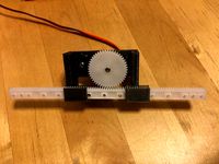
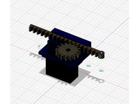
To overcome this I have used a larger cog, so now the rack can be driven over a larger range, which makes setting the servo up easier.
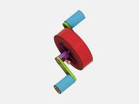
When assembling, the servo should be centred, and the cog placed on the servo so that the vertical marks are vertical. This should give you roughly symmetric movement of the drive rack.
The new design is better matched to LGB dimensions, so the "servo centre" should now be roughly "points centred" regardless of how you fit the drive to the points.
I have also designed an illuminated snap action indicator to show the points direction.
This uses a small offset drive that is placed on the "opposite" end of the rack, which engages with a small circular driveshaft that holds the actual indicator.
There are indicator variants with Arrows or RhB markings that then fit into the drive.
For illumination, a 3mm filament bulb can be placed in the indicator (or a small LED).
The snap action of the indicator should snap as as the points go over-centre, but it may be that you need to offset the drive slightly, so I have made drive pins with 0.5 and 1 mm offsets that you can use to "tweak" the action. The drive was designed to use the smaller "pin" but sometimes I find that the larger pin makes the indicator snap better.
There are two versions of the drive shaft that the pin engages with. The first has a "full" 90 degree drive and this seems to work well with non illuminated indicators. But I found that with the wires from the 3mm filament lamp the indicator was "dragging" and only moved about 60 degrees. To overcome this, I have added a second version of the drive with 60 degree drive angles, that forces the indicator to move slightly further, giving the full 90 degree movement to the indicator.
I use 1.7 by 10mm self tapping screws to hold everything together.
The servo should be a ES08DE or ES08MA, which for me fits the "S pinion".
The "9G" servo is roughly the same size (it is actually 1mm "greater height " ) , and takes the "L Pinion".https://youtu.be/2D8CQbFnBPE
I have included the 123D file if you wish to adapt this, but only for non commercial purposes.
Thanks also to Marius (https://www.thingiverse.com/2009marius15/about) who suggested the two part illuminated indicators, and who made and tested some early versions to help sort out the design.
I will leave this Object here for reference or if you need to print spare parts. The indicator parts should be interchangeable with the new design, but all other parts have been modified or re-drawn.
Comments from earlier versions...
There been comments about the pinions and servo fit:
My three gears (s,m,l) are supposed to have holes (hex holes) 3.9, 4.4 and 4.8mm flat to flat.
I discovered that I had two types of ES08MAII servos. -- presumably one is fake? --.
One has 4.7mm pinion (and is 11.9mm thick) , the other 3.9 (and is 11.6 mm thick) .
My examples of ES08DE have plastic pinions of 3.8 and are11.7 thick.
I also use TGY9081MG , with 4.8mm pinions, which is 12.2 thick and a bit longer, but the pinion to flange dimensions are the same so they can be interchanged with the ES08's.
The pinions designs are not exact fits, just sizes I hacked to work with some of my servos.
I also recently had pinion fit issues with some new prints, but realised that the pinion "hex hole" was getting distorted at the first layer, squeezing inwards, making fitting difficult. This is a consequence of the first layer being wider than the others for adhesion purposes. A quick knife bevel around the hex hole sorts this ok.
Other - (Even older!) Notes:
My previous points motor used a slightly smaller drive to the rack, which required that the servo turn almost to its full extent to make the points switch. This sometimes made setting the unit up on the track difficult, as the drivers could not always get the required servo range.
To overcome this I have used a larger cog, so now the rack can be driven over a larger range, which makes setting the servo up easier.
When assembling, the servo should be centred, and the cog placed on the servo so that the vertical marks are vertical. This should give you roughly symmetric movement of the drive rack.
The new design is better matched to LGB dimensions, so the "servo centre" should now be roughly "points centred" regardless of how you fit the drive to the points.
I have also designed an illuminated snap action indicator to show the points direction.
This uses a small offset drive that is placed on the "opposite" end of the rack, which engages with a small circular driveshaft that holds the actual indicator.
There are indicator variants with Arrows or RhB markings that then fit into the drive.
For illumination, a 3mm filament bulb can be placed in the indicator (or a small LED).
The snap action of the indicator should snap as as the points go over-centre, but it may be that you need to offset the drive slightly, so I have made drive pins with 0.5 and 1 mm offsets that you can use to "tweak" the action. The drive was designed to use the smaller "pin" but sometimes I find that the larger pin makes the indicator snap better.
There are two versions of the drive shaft that the pin engages with. The first has a "full" 90 degree drive and this seems to work well with non illuminated indicators. But I found that with the wires from the 3mm filament lamp the indicator was "dragging" and only moved about 60 degrees. To overcome this, I have added a second version of the drive with 60 degree drive angles, that forces the indicator to move slightly further, giving the full 90 degree movement to the indicator.
I use 1.7 by 10mm self tapping screws to hold everything together.
The servo should be a ES08DE or ES08MA, which for me fits the "S pinion".
The "9G" servo is roughly the same size (it is actually 1mm "greater height " ) , and takes the "L Pinion".https://youtu.be/2D8CQbFnBPE
I have included the 123D file if you wish to adapt this, but only for non commercial purposes.
Thanks also to Marius (https://www.thingiverse.com/2009marius15/about) who suggested the two part illuminated indicators, and who made and tested some early versions to help sort out the design.
Similar models
thingiverse
free
Points motor for Piko/LGB G Scale
...coder-mit-servo-funktionstaste-f0-f28-oder-weichenadresse-schaltbar-nachwippen-fahrreglersteuerung-glockenschwingen
15 mm x 33 mm
thingiverse
free

Simple G Scale Points Motor by dagnall53
...ers 1 and 3, which is a better match for some lgb points which are not set up for using sleepers 1 and 2 as in the original file.
grabcad
free

Low Drive Points
...low drive points
grabcad
servo operated rank and pinion drive for g scale garden railway points
thingiverse
free

Indicator holder for bed leveling and offset by thomasgerster97
...should be leveled and your z-offset should be point on.
note: if your z-offset is off it might be your steps per mm in the z-axis
thingiverse
free
Rack and Pinion Linear Actuator for Micro Servo
...n super glued to the servo horn. i also clipped the servo horn to make it shorter.
full build video: https://youtu.be/kujzazrud4e
thingiverse
free

Rack and Pinion Hand Cranked Drive by 3DPRINTINGWORLD
...together and superglue the handle into the pinion, but mine stayed together without superglue.
videohttps://youtu.be/0l3sgtrwmdc
thingiverse
free

Pegboard snap-fit pin
...rease strength and ease of printing, but there is an option to print straight up and down as well (which would require supports).
thingiverse
free
MG995 Servo linear actuator by sbabber
...mount, which i reccomend highly.
i hope this helps anyone. i made this for a syringe pump, which works great with this addition!
thingiverse
free

Bogie drive wheel
... the wheel. the hubs simply push into the wheel centres after fitting the nut. included are centres for drive and trailer wheels.
thingiverse
free
Planetary Gear handles by bradjshannon
...m hex bore.
the other handle is the "planet carrier," which drives 5 planet gears with posts centered 16.11mm radially.
Dagnall53
thingiverse
free
5SCased tripod mount by dagnall53
...53
thingiverse
just a remix, slightly larger housing to take a cased 5s
included the 123d file so its easier to remix next time!
thingiverse
free

Walker Type Nautical Log by dagnall53
...lacement. designed to give approximately 20,000 pulses per nautical mile.
must be calibrated by user before any navigational use!
thingiverse
free
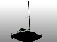
Catalac 8m Catamaran Cruiser Boat by dagnall53
...rawn originally in softfx, but the stl is unfortunately not printable as it is.
feel free to adapt to improve and make printable.
thingiverse
free

Points Servo Drive (Train track) by dagnall53
... spring mechanism allows the trains to push past "closed" points without derailing.
video: http://youtu.be/xdbzoc0kwsc
thingiverse
free

Man with CAP 1:32 scale by dagnall53
...n guard for a 1:32 scale railway.
supports to help print were made in meshmixer, so it should print "without supports".
thingiverse
free

Ticket Office and WHS Kiosk by dagnall53
...ches) and two servo drives to drive points at the station. the code is available here https://github.com/dagnall53/espwifirocnet
thingiverse
free

Dimension test for coach side part of couplings by dagnall53
...://www.thingiverse.com/thing:1000218
but has not been built or tested and would need some tidying up to work as a coach coupling.
thingiverse
free
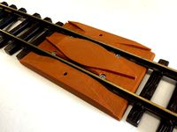
G scale Re-Railer by dagnall53
... the re-railer bottom surface.
i have attached the 123d file so you can modify the design if your railway does not use lgb locos.
thingiverse
free

Magnetic electrical connector for LGB Carriages and Trains by dagnall53
...ave used this to couple power from the engine to light the carriages without having to have track brushes on the carriage wheels.
thingiverse
free

G scale arch by dagnall53
...id not get all the "bricks" perfectly, but it looks good when painted with sandstone type paints. feel free to modify!
Indicators
3ddd
$1

Indice Sofa
...indice sofa
3ddd
indice sofa , roche bobois
indice sofa roche bobois
archive3d
free
Indicator 3D Model
...sor indicator pointer
indicator n130508 - 3d model (*.gsm+*.3ds) for interior 3d visualization.
turbosquid
$26

Km indicator
...squid
royalty free 3d model km indicator for download as max on turbosquid: 3d models for games, architecture, videos. (1153786)
turbosquid
free

Road Indicator
...d
royalty free 3d model road indicator for download as blend on turbosquid: 3d models for games, architecture, videos. (1299938)
turbosquid
$30
Dial Indicator
...ree 3d model dial indicator for download as 3ds, max, and obj on turbosquid: 3d models for games, architecture, videos. (1302779)
3d_export
$7
dial indicator
...r is any of various instruments used to accurately measure small distances and angles, and amplify them to make them more obvious
turbosquid
$3

Power Indicator
...ree 3d model power indicator for download as ma, obj, and fbx on turbosquid: 3d models for games, architecture, videos. (1143828)
turbosquid
$50

Digital Indicator
... available on turbo squid, the world's leading provider of digital 3d models for visualization, films, television, and games.
turbosquid
$50

altitude indicator
... available on turbo squid, the world's leading provider of digital 3d models for visualization, films, television, and games.
turbosquid
$25
Dial Indicator
... available on turbo squid, the world's leading provider of digital 3d models for visualization, films, television, and games.
Improved
cg_studio
$49

Robot Z300 (improved version)3d model
...o
.3ds .fbx .max .obj - robot z300 (improved version) 3d model, royalty free license available, instant download after purchase.
3d_export
$39

Robot Z300 improved version 3D Model
...fantasy sci-fi robots bot humanoid droid sci fi materials character
robot z300 improved version 3d model alekrazum 55067 3dexport
3d_export
$75

CV-90 Improved
...nnon. export versions are fitted with hägglunds e-series turrets, armed with either a 30 mm mk44 or a 35 mm bushmaster autocannon
turbosquid
$55

(Important textures coming back soon after improvements)Cuboid gazebo bench area
... available on turbo squid, the world's leading provider of digital 3d models for visualization, films, television, and games.
3d_export
$15

COMPLETE AUDI 80-100 SHIFT LEVER REPAIR KIT WITH IMPROVED BUSHING
...dexport
• sleeve - 1 pc. • elastic band - 1 pc. • hinge - 1 pc. audi 100c3 audi 100 c4 audi 80 b3 (checked) audi 80 b4 (checked)
3d_export
$7

REPAIR KIT FOR GEARSHIFT LEVER AUDI 80-100 IMPROVED
...ar of the gum is excluded. - rusk - 1 pc. - elastic band - 1 pc. audi 100c3 audi 100 c4 audi 80 b3 (checked) audi 80 b4 (checked)
3d_export
$30
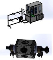
cup mask machine front section stereo mask manufacturing machine improved version
...ing rack cad outsourcing list. the drawings are mature drawings that have been produced.<br>drawing version solidworks 2018
3d_export
free

oven - forno
...oven - forno
3dexport
gradually i'm trying to improve my 3d.
3d_export
$75

T-55
...nally, but these improvements made the tank more efficient and lethal. the t-55 was officially adopted by the soviet army in 1958
3d_export
$5

civil registration authorities
...civil registration authorities
3dexport
city wedding square. the model can be used for projects, to improve the project, etc.
Points
3ddd
$1

Point
...nt , садовая мебель
кресло tahiti ref. 72096 (74x95x93)
пуф tahiti ref. 72052 (54x71x46)
3ddd
free

Point
...f. 71541 (220x100x83)
столики combi ref. 74470 (50x50x59) и ref. 74471 (50x50x79)
стол журнальный diabolo ref. 74151 (130x130x35)
3ddd
$1

Point armchair
... ротанг
сайт производителяhttp://www.point1920.com/archivos/varios/point-feelings/
turbosquid
$21

Loft Point
...turbosquid
royalty free 3d model loft point for download as on turbosquid: 3d models for games, architecture, videos. (1446385)
turbosquid
$20

Point Of Sale
...id
royalty free 3d model point of sale for download as blend on turbosquid: 3d models for games, architecture, videos. (1661269)
turbosquid
$8
Sale Points
...y free 3d model sale points for download as 3ds, max, and obj on turbosquid: 3d models for games, architecture, videos. (1301072)
turbosquid
$3
Point Of Sale
...free 3d model point of sale for download as 3ds, max, and obj on turbosquid: 3d models for games, architecture, videos. (1301061)
turbosquid
$250

Crown Point
... available on turbo squid, the world's leading provider of digital 3d models for visualization, films, television, and games.
turbosquid
$25

Flash point
... available on turbo squid, the world's leading provider of digital 3d models for visualization, films, television, and games.
turbosquid
$22

Ball-Point
... available on turbo squid, the world's leading provider of digital 3d models for visualization, films, television, and games.
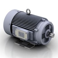
Motor
archibase_planet
free
Motor
...base planet
motor motor engine engine electric motor
motor wagner n250213 - 3d model (*.gsm+*.3ds) for interior 3d visualization.
archibase_planet
free
Motor
...motor
archibase planet
motor motor engine engine
motor n151112 - 3d model (*.gsm+*.3ds) for interior 3d visualization.
archibase_planet
free
Motor
...motor
archibase planet
motor motor engine engine
motor n150615 - 3d model (*.gsm+*.3ds+*.max) for interior 3d visualization.
turbosquid
$15
Motor
...otor
turbosquid
royalty free 3d model motor for download as on turbosquid: 3d models for games, architecture, videos. (1639404)
3d_ocean
$5
Electric motor
...electric motor
3docean
car electric engine industry motor phase train vehicle
an electric motor enjoy!
3d_ocean
$18
Electric Motor
...electric motor
3docean
electric motor engine machine mover parts
3d model electric motor for hoist crane
turbosquid
$29

Motor
... available on turbo squid, the world's leading provider of digital 3d models for visualization, films, television, and games.
turbosquid
$5
Motor
... available on turbo squid, the world's leading provider of digital 3d models for visualization, films, television, and games.
3d_export
$5
electric motor
...electric motor
3dexport
electric motor use for industrial purposes
3d_export
$5

servo motor
...tor
3dexport
it's a simple part of servo motor 0.75kw for used in machines assembly to show specified motor in own project.