Thingiverse
Improved K40 laser cutter Combiner Mount for red dot laser by DOugL
by Thingiverse
Last crawled date: 2 years, 10 months ago
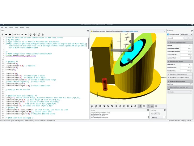
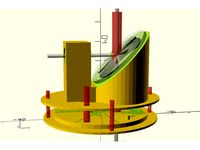
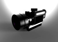
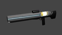
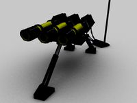
This is my NEW custom K40 Combiner Mount for adding a red dot laser pointer to a K40 laser cutter. It's defaulted to fit the American Photonics(APC) 25mm combiner(link below).
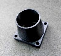
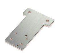
To get the customized for where your laser exits from the laser compartment, use the K40 Combiner Mount Test Plug( https://www.thingiverse.com/thing:2915278 ). With it you determine your laser cutter's beam location within the large round hole in the back of the laser cutter. Then use Customizer to set the X and Y positions for this and then select each part and save the STL files. There is also a new fitTest part which will give you a small block with 3 holes in it. The holes are for the combiner, the laser pointer, m3 screw hole. Use adjustment values in Customizer to adjust hole diameters so your 3D printer creates usable parts.
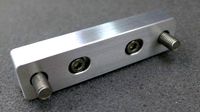
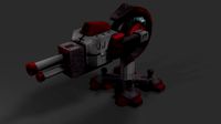
Minor Adjustments can be done with the red dot laser by shimming it so it ends up lined up with the same dot a pulse burn produces at your work piece. The default APC Type 2 combiner has 2 m3 screw holes next to the combiner mount. Use 2 8-10mm M3 screws to hold the combiner in place. The Type 1 combiner lens mount consists of a total of 4 screws. Two screws hole the combiner lens mount to the plastic part and the other two screws push the combiner lens mount off of the plastic part. I originally obtained my beam combiner and lens mount from a piece of used equipment. For the APC 25mm combiner you will fit new product here:https://american-photonics.myshopify.com/collections/mark-and-engrave-co2-and-fiber-laser/products/copy-of-15mm-znse-focus-lens-1-5mm-edge-thickness-trotec-speedy-100-by-apc-c02-laser-10-6um?variant=32958753472573
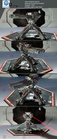
After doing the Combiner Mount Test Plug and 3D printing my parts I first made sure my M3 screws fit the Combiner Mount Plug by pre-fitting. I also made sure the M3 screws passed through but fit tightly to the associated holes in the Combiner Mount. Also see that the 2 alignment pins in the Plug fit in the associated holes in the Combiner Mount. Clean out the 2 thin walls of the laser mount and see that the laser pointer fits snugly in the mount hole.
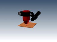
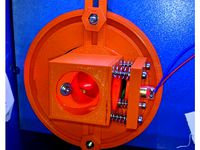
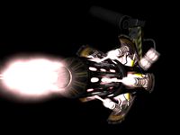
For assembly, I put the Combiner Plug into the hole from the laser tube compartment and used a piece of tape to hold in place. After mounting the red dot laser and the combiner(side marked "IN" faces into the Combiner Mount and towards the laser tube/Mirror #1. I put the 2 M3 screws used to mount the Combiner Mount to the Combiner Plug into the Combiner Mount just enough to hold them. With a hand holding the Plug in place I lined up the top screw on the Combiner Mount with the hole in the Plug and slipped the allen wrench on the screw and turned a few turns. Do the same with the bottom Mount/Plug screw and then tighten them making sure the pins on the Plug are interfacing the Mount. Make sure the red dot laser is at 3 o'clock or 9 o'clock and see if your red dot is showing up on your work surface centered below the lens. Shim or adjust the red dot laser or holder as needed. I added 2 dots of glue on the red dot laser to be sure vibration does not change its position. Test fire your laser to see that your alignment is correct and the red dot and CO2 laser beam are coincident.
To get the customized for where your laser exits from the laser compartment, use the K40 Combiner Mount Test Plug( https://www.thingiverse.com/thing:2915278 ). With it you determine your laser cutter's beam location within the large round hole in the back of the laser cutter. Then use Customizer to set the X and Y positions for this and then select each part and save the STL files. There is also a new fitTest part which will give you a small block with 3 holes in it. The holes are for the combiner, the laser pointer, m3 screw hole. Use adjustment values in Customizer to adjust hole diameters so your 3D printer creates usable parts.
Minor Adjustments can be done with the red dot laser by shimming it so it ends up lined up with the same dot a pulse burn produces at your work piece. The default APC Type 2 combiner has 2 m3 screw holes next to the combiner mount. Use 2 8-10mm M3 screws to hold the combiner in place. The Type 1 combiner lens mount consists of a total of 4 screws. Two screws hole the combiner lens mount to the plastic part and the other two screws push the combiner lens mount off of the plastic part. I originally obtained my beam combiner and lens mount from a piece of used equipment. For the APC 25mm combiner you will fit new product here:https://american-photonics.myshopify.com/collections/mark-and-engrave-co2-and-fiber-laser/products/copy-of-15mm-znse-focus-lens-1-5mm-edge-thickness-trotec-speedy-100-by-apc-c02-laser-10-6um?variant=32958753472573
After doing the Combiner Mount Test Plug and 3D printing my parts I first made sure my M3 screws fit the Combiner Mount Plug by pre-fitting. I also made sure the M3 screws passed through but fit tightly to the associated holes in the Combiner Mount. Also see that the 2 alignment pins in the Plug fit in the associated holes in the Combiner Mount. Clean out the 2 thin walls of the laser mount and see that the laser pointer fits snugly in the mount hole.
For assembly, I put the Combiner Plug into the hole from the laser tube compartment and used a piece of tape to hold in place. After mounting the red dot laser and the combiner(side marked "IN" faces into the Combiner Mount and towards the laser tube/Mirror #1. I put the 2 M3 screws used to mount the Combiner Mount to the Combiner Plug into the Combiner Mount just enough to hold them. With a hand holding the Plug in place I lined up the top screw on the Combiner Mount with the hole in the Plug and slipped the allen wrench on the screw and turned a few turns. Do the same with the bottom Mount/Plug screw and then tighten them making sure the pins on the Plug are interfacing the Mount. Make sure the red dot laser is at 3 o'clock or 9 o'clock and see if your red dot is showing up on your work surface centered below the lens. Shim or adjust the red dot laser or holder as needed. I added 2 dots of glue on the red dot laser to be sure vibration does not change its position. Test fire your laser to see that your alignment is correct and the red dot and CO2 laser beam are coincident.
Similar models
thingiverse
free
K40 laser cutter Combiner Mount for red dot laser by DOugL
...rews push the combiner lens mount off of the plastic part. i obtained my beam combiner lens mount from a piece of used equipment.
thingiverse
free
Red Dot Laser Pointer for 40Watt laser cutter. by Preso
...e focus distance will be correct. an m4 screw is used to tighten the clamp and an m3 screw is used to fix the laser holder angle.
thingiverse
free
Beam Combiner for K40 Laser by erpel09
...he center
put a piece of thermal paper on mirror 2, fire your laser and use the 4 m2 screws to adjust the position of the red dot
thingiverse
free

k40 Red dot laser pointer holder by xile6
...le and light weight red dot laser holder for my k40 laser cutter.
two models. on simple has the red dot laser mount trimmed down.
thingiverse
free

K40 Drag Chain by xile6
...rear mount i believe i used 6 or 8mm
for the carriage i used one m3 8mm
for the chain to carriage roller one m3 20mm and 1 m3 nut
thingiverse
free

K40 laser cutter Combiner Mount Test Plug by DOugL
... to the laser head and test material with little to no smoke seen on the test plug. i printed in pla because abs smoke is toxic.
thingiverse
free

K40 Co2 laser nozzle air assist laser pointer
...andard 50.8mm(2.0")focal length lens. side key is for red laser pointer. red dot laser pointer holder will be uploaded soon.
thingiverse
free

K40 Chinese Laser Air Assist and Dual Line Laser Pointer by Demonic69
... can be mounted through the mirror/lens holder frame.
update 12/10/2015 - added the ball-type holders for the 12mm laser modules.
thingiverse
free

K40 Chinese Laser Cutter Lens Carriage Spacer Screw Holder by yuxin
....
the hex holes are (very) slightly loose to compensate for 3d printer oozing. the 123d files are also uploaded for adjustments.
thingiverse
free

K40 Laser Cutter Drag Chain Mount by DOugL
...ger interferes with the combiner lens and laser pointer thing i've added to my k40. https://www.thingiverse.com/thing:2915288
Dougl
cg_studio
$169
OH-63d model
...oh-63d model cgstudio aircraft helicopter boeing mcdonnell dougls huges 369 oh-6 oh-6a cayuse ah-6 ah-6j navy army...
thingiverse
free

Barb Generator v3 - remix by DOugL
...with a fix so that the barbs have a through hole and don't need to be drilled out. only tested with the single default barb.
thingiverse
free

K40 Laser Gauge V3.1 by DOugL
...irst cut of this resulted in 50.33mm so it might need tweeking or my focus might have been off and the kerf larger than expected.
thingiverse
free

DIY Artificial Eyes by DOugL
... so the tendon/floss cleared the guide hole well. i didn't change the eye sockets so they are still listed with the number 2.
thingiverse
free
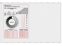
Laser Cutter Material Test Card remix for LightBurn by DOugL
...y section(making a donut) and i changed the areas of customization into lightburn text objects for easy editing within lightburn.
thingiverse
free

Ortur LaserMaster lens holder by DOugL
.... knurled versions have 30mm od knob.
2 sizes of o-rings it seems so i have posted a knurled versions with 1mm od and a 1.1mm od.
thingiverse
free

Countertop Coffee Mug and Cup Strainer / Dryer by DOugL
...the counter top and cups from staying moist.
change cupcount and/or cupod to customize for more cups and/or cup diameter changes.
thingiverse
free

Mini Kossel JHead 30mm PEEK fan mount by DOugL
...ducts. this design is in preparations for using the "cooling duct that works"(http://www.thingiverse.com/thing:225126).
thingiverse
free

DIYRoboCar inverted donkeycar mounting plate by DOugL
...the mcad utility package so you'll want to download and install that. you can get it from here: https://github.com/elmom/mcad
thingiverse
free
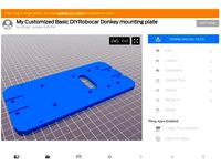
Basic DIYRobocar Donkey mounting plate by DOugL
...the mcad utility package so you'll want to download and install that. you can get it from here: https://github.com/elmom/mcad
K40
turbosquid
$9

Jaipur Rugs K40
... available on turbo squid, the world's leading provider of digital 3d models for visualization, films, television, and games.
3ddd
$1

FONTEALTA K40-S
...fontealta k40-s
3ddd
смеситель , fontealta
sink mixer withswivel spout, in inox steel
3ddd
$1

FONTEALTA K40-F
...fontealta k40-f
3ddd
смеситель , fontealta
sink mixer withswivel spout, in inox steel
turbosquid
$22

XIAOMI REDMI K40 PRO
...o for download as blend, blend, blend, fbx, dae, obj, and stl on turbosquid: 3d models for games, architecture, videos. (1697685)
turbosquid
$15

Marcel Breuer K40 Sofa Table
... available on turbo squid, the world's leading provider of digital 3d models for visualization, films, television, and games.
3d_export
$22
xiaomi redmi k40 pro
...e so that the exported files (.dae, .stl, .usdc, .obj and .fbx) is ok please tell me in private message if you have any problems.
3d_export
$30

xiaomi redmi k40 gaming 2021
...reviews is made with lux core render free add-on render p.s .: priority - produced in blender program builds -** blender 2.92.0**
3d_export
$5
Chevy k20 3D Model
...chevy k20 3d model 3dexport chevy k20 k30 k40 k50 k5 blazer pickup dodge ford rims wheels tires...
thingiverse
free

K40 BigDesk (170x265m)
...k40 bigdesk (170x265m)
thingiverse
a bigdesk for the k40
in progress....
thingiverse
free

K40 handle by rafaljot
...k40 handle by rafaljot
thingiverse
handle for k40 co2 laser.
Dot
3ddd
free
DOT
...dot
3ddd
dot , itre
элитные итальянские светильники в стиле модерн и hi tech. itre
3ddd
free

KALE - DOT
...ame, dot is its style. round. circular. playful and personal. elegant. striking. dot is the comibination of fashion and function.
3ddd
$1
Dot dresser
...dot dresser
3ddd
комод
dot dresser
turbosquid
$14

DOT
... available on turbo squid, the world's leading provider of digital 3d models for visualization, films, television, and games.
turbosquid
$4

Dot
... available on turbo squid, the world's leading provider of digital 3d models for visualization, films, television, and games.
3ddd
free
BLU DOT
... dot , тумба
blu dot modu-licious bedside table
модель md1-bdtb00
размеры 460х610х480 мм
design_connected
$11

Dot Pillow
...dot pillow
designconnected
hay dot pillow computer generated 3d model.
turbosquid
$4
Red Dot
...turbosquid
royalty free 3d model red dot for download as obj on turbosquid: 3d models for games, architecture, videos. (1341491)
turbosquid
$6

Starfish dotted
...lty free 3d model starfish dotted for download as obj and stl on turbosquid: 3d models for games, architecture, videos. (1554444)
3ddd
$1
Dots Panel
...
3ddd
панель
панель dots от woodlives из гипса под покраску
размер - 30*30 см
варианты окрашивания возможны любые.
woodlives.ru
Cutter
archibase_planet
free
Cutter
...cutter
archibase planet
cutter mill milling cutter
cutter 2 n050712 - 3d model (*.gsm+*.3ds) for interior 3d visualization.
3d_export
$10
pipe cutter
...pipe cutter
3dexport
pipe cutter
3d_export
$8
Grass Cutter
...grass cutter
3dexport
grass cutter
turbosquid
$5

Cutter
...alty free 3d model cutter for download as ige, stl, and sldpr on turbosquid: 3d models for games, architecture, videos. (1505202)
turbosquid
$29
Cutter
... available on turbo squid, the world's leading provider of digital 3d models for visualization, films, television, and games.
turbosquid
$15

Cutter
... available on turbo squid, the world's leading provider of digital 3d models for visualization, films, television, and games.
turbosquid
$9

Cutter
... available on turbo squid, the world's leading provider of digital 3d models for visualization, films, television, and games.
turbosquid
$3
cutter
... available on turbo squid, the world's leading provider of digital 3d models for visualization, films, television, and games.
turbosquid
$1

cutter
... available on turbo squid, the world's leading provider of digital 3d models for visualization, films, television, and games.
turbosquid
free
Cutter
... available on turbo squid, the world's leading provider of digital 3d models for visualization, films, television, and games.
Laser
3d_export
$5
laser
...laser
3dexport
a 3d laser
3d_export
free
cnc 3dp laser nozzle for 2w laser opt lasers
...logy that gave birth to cutting and engraving laser heads this laser nozzle was designed for, read the article in the link below:
3d_export
free
cnc laser mount opt lasers
...eive the engraving and cutting laser heads this cnc machine laser mount was designed for, read the article on the following page:
turbosquid
$20
Laser
... available on turbo squid, the world's leading provider of digital 3d models for visualization, films, television, and games.
turbosquid
$15
Laser
... available on turbo squid, the world's leading provider of digital 3d models for visualization, films, television, and games.
turbosquid
$3
Laser
... available on turbo squid, the world's leading provider of digital 3d models for visualization, films, television, and games.
3d_export
$5

laser sword
...laser sword
3dexport
it is a blue laser sword with a metal frame
3d_ocean
$19
Laser Turret
...be used in any sf type of game, especially in tower defense games. - laser turret: 3025 polygons - props: 270 polygons - textu...
3d_export
free
workbee cnc laser mount for opt lasers
...the specifications of engraving and cutting laser heads this mount was designed for, please take a look at the following website:
3d_export
free

shapeoko cnc laser mount for opt lasers
...ind out the opportunities that adding a cutting and engraving laser head to your cnc can bring, take a look at the website below:
Improved
cg_studio
$49
Robot Z300 (improved version)3d model
...o
.3ds .fbx .max .obj - robot z300 (improved version) 3d model, royalty free license available, instant download after purchase.
3d_export
$39

Robot Z300 improved version 3D Model
...fantasy sci-fi robots bot humanoid droid sci fi materials character
robot z300 improved version 3d model alekrazum 55067 3dexport
3d_export
$75
CV-90 Improved
...nnon. export versions are fitted with hägglunds e-series turrets, armed with either a 30 mm mk44 or a 35 mm bushmaster autocannon
turbosquid
$55
(Important textures coming back soon after improvements)Cuboid gazebo bench area
... available on turbo squid, the world's leading provider of digital 3d models for visualization, films, television, and games.
3d_export
$15

COMPLETE AUDI 80-100 SHIFT LEVER REPAIR KIT WITH IMPROVED BUSHING
...dexport
• sleeve - 1 pc. • elastic band - 1 pc. • hinge - 1 pc. audi 100c3 audi 100 c4 audi 80 b3 (checked) audi 80 b4 (checked)
3d_export
$7

REPAIR KIT FOR GEARSHIFT LEVER AUDI 80-100 IMPROVED
...ar of the gum is excluded. - rusk - 1 pc. - elastic band - 1 pc. audi 100c3 audi 100 c4 audi 80 b3 (checked) audi 80 b4 (checked)
3d_export
$30
cup mask machine front section stereo mask manufacturing machine improved version
...ing rack cad outsourcing list. the drawings are mature drawings that have been produced.<br>drawing version solidworks 2018
3d_export
free
oven - forno
...oven - forno
3dexport
gradually i'm trying to improve my 3d.
3d_export
$75
T-55
...nally, but these improvements made the tank more efficient and lethal. the t-55 was officially adopted by the soviet army in 1958
3d_export
$5

civil registration authorities
...civil registration authorities
3dexport
city wedding square. the model can be used for projects, to improve the project, etc.
Combiner
3d_export
$15

combine harvester
...combine harvester
3dexport
combine harvester.hope you like it!<br>formats..max.fbx.obj.3ds
turbosquid
$9

COMBINATION PADLOCK
...royalty free 3d model combination padlock for download as max on turbosquid: 3d models for games, architecture, videos. (1485626)
turbosquid
$24

The Combination Padlock
... 3d model the combination padlock for download as c4d and fbx on turbosquid: 3d models for games, architecture, videos. (1668991)
turbosquid
$10

Combination Padlock
...free 3d model combination padlock for download as max and obj on turbosquid: 3d models for games, architecture, videos. (1340019)
3d_export
$10

modern ornament combination
...modern ornament combination
3dexport
modern ornament combination
turbosquid
$35
Combine Harvester
...d model combine harvester for download as blend, obj, and fbx on turbosquid: 3d models for games, architecture, videos. (1646743)
turbosquid
$19

Combination for climbing
...el combination for climbing for download as max, obj, and fbx on turbosquid: 3d models for games, architecture, videos. (1601482)
turbosquid
$3

Combination Pliers
... 3d model combination pliers for download as ma, obj, and fbx on turbosquid: 3d models for games, architecture, videos. (1393273)
3d_export
$10

modern sofa combination
...modern sofa combination
3dexport
modern sofa combination vr4.1
3d_export
$5
beet combine harvester
...beet combine harvester
3dexport
beet combine harvester step
Red
3ddd
$1

red bull
...red bull
3ddd
red bull
red bull can
3d_ocean
$4
Red brick
...red brick
3docean
brick low poly red
red brick
3d_export
$40

red panda
...red panda
3dexport
red panda
3d_export
$5

eggchair red
...eggchair red
3dexport
a red eggchair
3ddd
$1

Red curtain
...red curtain
3ddd
red curtain
3d_export
$5

Red barrel
...red barrel
3dexport
its a red barrel
3ddd
$1
Red bicycle
...red bicycle
3ddd
велосипед
red bicycle
3ddd
$1
RED COLLECTION
...red collection
3ddd
витрина
red collection
3ddd
$1
RED COLLECTION
...red collection
3ddd
обеденный
red collection
3ddd
$1
RED COLLECTION
...red collection
3ddd
витрина
red collection
Mount
3d_export
free

mounting bracket
...mounting plate is the portion of a hinge that attaches to the wood. mounting plates can be used indoors, cabinetry and furniture.
turbosquid
$2

MOUNTING
... available on turbo squid, the world's leading provider of digital 3d models for visualization, films, television, and games.
turbosquid
free

Mounts
... available on turbo squid, the world's leading provider of digital 3d models for visualization, films, television, and games.
turbosquid
free

Mount Fuji
...fuji
turbosquid
free 3d model mount fuji for download as obj on turbosquid: 3d models for games, architecture, videos. (1579977)
3d_export
$5

Headphone mount LR
...headphone mount lr
3dexport
headphone mount l+r
turbosquid
$39

Mount rainier
...quid
royalty free 3d model mount rainier for download as fbx on turbosquid: 3d models for games, architecture, videos. (1492586)
turbosquid
$5

pipe mounting
...quid
royalty free 3d model pipe mounting for download as obj on turbosquid: 3d models for games, architecture, videos. (1293744)
turbosquid
$3

Mounting Tires
...uid
royalty free 3d model mounting tires for download as fbx on turbosquid: 3d models for games, architecture, videos. (1708511)
3d_export
$5

Magnetic GoPro Mount
...pro mount
3dexport
cool magnetic mount for gopro. allows you to mount the camera on flat metal surfaces and get exclusive shots.
turbosquid
$5

Stone Mount
...ty free 3d model stone mount for download as ma, obj, and fbx on turbosquid: 3d models for games, architecture, videos. (1370306)