Thingiverse

IKEA Lack Extractor Fan Assembly by DrLeFonque
by Thingiverse
Last crawled date: 3 years, 1 month ago
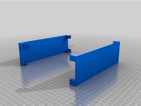
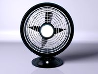
This is my first CAD design, ever. This is an extractor fan assembly designed to be used on an IKEA Lack enclosure setup. The aim was to have an extractor fan (or two) mounted on top of the enclosure to extract heat (for PLA) and fumes (for ABS) from the enclosure when required.
Updates
Update (2018/04/05): I printed out the bottom part of the fan assembly (IKEA_Lack_Extractor_Fan_Assembly_Bottom.stl) and noticed that there was a small 1mm gap between between the inner wall and one side of the fan mount. I've corrected this and uploaded the fixed STL file.
Update (2018/04/05): I printed the top half of the assembly (IKEA_Lack_Extractor_Fan_Assembly_TOP.stl) and found another error I made in the design. Whilst making the slot system so that both halves slot into one another, I forgot that this would take the height (excluding the flared ends) from 50mm to 48mm. Tomorrow I will correct of this and upload the new top half with an extra 2mm added to account for this.
Update (2018/04/06): I have made the 2mm adjustment to the top half of the assembly, the whole assembly should now fit precisely. I am going to reprint the top assembly over the weekend and verify that all the holes line up, then this should be a complete and functional build.
Update (2018/04/06): Added duct mount
Update (2018/04/09): The duct mount was a little too big for the hole it was meant to fit into, I have amended this and uploaded the fixed file. I've also confirmed that all the holes line up, so this is now a complete and functional build.
Parts
For this assembly I've purchased the following parts:
Scythe GlideStream 120mm PWM SC: https://www.amazon.co.uk/gp/product/B01D64OXA4/
The fan comes with a 3 speed controller switch that allows you to increase or decrease RPM's based on your needs. I'm going to be rewiring this to a control panel on the front of my enclosure (still working on this), which will allow me to turn the fans on and off and control the speed as required. There is a hole in the bottom part of the assembly to run the wiring through the enclosure.
Active Carbon Filter (2mm): https://www.amazon.co.uk/gp/product/B06XF5MWWK/
The active carbon filter will (hopefully) neutralise the ABS fumes. If this isn't the case then I'll make another top half with an adaptor where you can attach a duct and pump the ABS fumes out of a window or something.
Flexible Fan Ducting: https://www.amazon.co.uk/White-Flexible-Fan-Ducting-Extractor/dp/B011OOQ9PA/
Added a duct mount so you can attach some 100mm (4" in freedom units) flexible fan ducting. I've also added a notch around the mount to secure ducting with a zip tie (less than 5mm thick).
You'll need 4 x M3 screws and nuts to hold the fan and whole assembly together (including duct mount, if using). By my estimates, you'll need 40mm M3 screws (without duct) or 42mm screws (with duct).
Here are the TinkerCAD files, if you want to remix the design: https://www.tinkercad.com/things/25ztyGigLsC#/
As this is my first attempt at making a CAD design for 3D printing, feedback is welcome. Any suggestions on how to optimize the design for 3D printing is also welcome.
Similar models
thingiverse
free

Fume Extractor - 120mm Fan Shroud & Duct Adaptor by Tez_Gelmir
...pter reduces from 120mm to 85mm diameter sleeve to suit the flexible downpipe available from bunnings in australia for $9.90 aud.
thingiverse
free
Fume Extractor 200m Fan by jtranfpv
...
print 2 top-bottom plates
print 2 side plates
print 1 front plates
print 1 back plates
assembly required by fitting in the slots
thingiverse
free

Creality LD-002R Fume Extractor by BostonBowser
...on a cover to that hole in the enclosure.
you will need to power the fan with a 12v power supply or some sort of voltage source.
thingiverse
free

Solder Station Fume Extractor by vo1pwf
...ngiverse
a home made fume extractor made from
80mm pc fan
3d printed enclosure
activated filter
i added a switch for easy on/off
thingiverse
free
![80mm Fans (2) to 4" Dryer Duct [Pairs well with Da Vinci 1.0 Fan Mount for exhaust] by rickschrader](/t/8918295.jpg)
80mm Fans (2) to 4" Dryer Duct [Pairs well with Da Vinci 1.0 Fan Mount for exhaust] by rickschrader
... all of the abs-printing smell (and arguably dangerous fumes) from my area.
i printed with no supports and it turned out great.
thingiverse
free

Remixed 3d fume extractor right side
...o the slot for assembly. i added a channel to the left if the wiring hole that lets the wiring pass in and the fan sit correctly.
thingiverse
free

CR-10 - Ultimate Blow Me Twice by ketchu13
...mount, part cooler by louiscooper" at this stage of progress
thanks to them, take a look at others designs by these authors
thingiverse
free

Soldering Fume Extractor for 120mm Fan by twistedartwork
.... another option would be to connect it to some sort of duct but then you would need to design an adaptor for your specific duct.
thingiverse
free

Cooling Unit for Filastruder Fume Extraction Enclosure by mrflippant
...print without support.
you'll need parts from the fume extraction enclosure that this is remixed from to complete the system.
thingiverse
free

Super Suction Fume Extractor by spectura
... much so that you really hardly have to be close to it for the smoke to get sucked up!
based of the simple solder fume fan by orc
Drlefonque
thingiverse
free
Automatic Fire Extinguisher Mount by DrLeFonque
...n be easily removed.
here are the tinkercad files, if you want to remix the design: https://www.tinkercad.com/things/ic3zwawhxa5
thingiverse
free

D&D Initiative Tracker by DrLeFonque
...y feedback and suggestions on how these trackers can be improved, any good suggestions i get i'll implement into the design.
Extractor
turbosquid
$35
Extractor
... available on turbo squid, the world's leading provider of digital 3d models for visualization, films, television, and games.
3d_export
$5
kitchen extractor
...kitchen extractor
3dexport
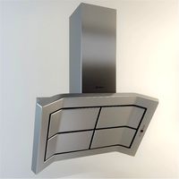
extractor hood for kitchen in stainless steel with blue tempered glass, very modern.
3ddd
free
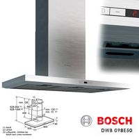
Extractor Bosch DWB098E50
...extractor bosch dwb098e50
3ddd
вытяжка , bosch
extractor bosch dwb098e50
3ddd
free
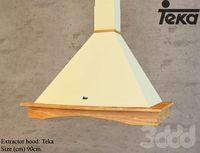
Teka - Extractor hood
...teka - extractor hood
3ddd
teka , вытяжка
teka - extractor hood
turbosquid
$1
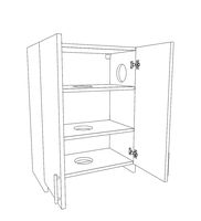
Extractor cupboard
...
royalty free 3d model extractor cupboard for download as max on turbosquid: 3d models for games, architecture, videos. (1161308)
turbosquid
$30
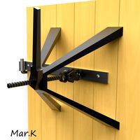
Lock extractor
... available on turbo squid, the world's leading provider of digital 3d models for visualization, films, television, and games.
turbosquid
free
air extractor
... available on turbo squid, the world's leading provider of digital 3d models for visualization, films, television, and games.
turbosquid
$59
Vehicle Exhaust Extractor
...3d model vehicle exhaust extractor for download as ma and fbx on turbosquid: 3d models for games, architecture, videos. (1689744)
turbosquid
$29
Liquid Liquid Extractor
... available on turbo squid, the world's leading provider of digital 3d models for visualization, films, television, and games.
turbosquid
$15
Bosch Extractor Modern
... available on turbo squid, the world's leading provider of digital 3d models for visualization, films, television, and games.
Lack
3d_export
$5

LACK LACK Coffee table white 90x55 cm IKEA
..., white, 90x55 cm ikea<br>https://www.ikea.com/ru/ru/p/lack-lakk-zhurnalnyy-stol-belyy-50449907/?ysclid=l8zshj49w6656165430
turbosquid
$4

Ikea Lack
... available on turbo squid, the world's leading provider of digital 3d models for visualization, films, television, and games.
3ddd
$1
IKEA Lack Coffee Table
... кофейный
ikea lack coffee tablehttp://www.ikea.com/gb/en/catalog/products/00104291
turbosquid
$5

IKEA Lack Table
...ack table for download as blend, blend, unitypackage, and fbx on turbosquid: 3d models for games, architecture, videos. (1623135)
turbosquid
$10

Ikea Lack Set
... available on turbo squid, the world's leading provider of digital 3d models for visualization, films, television, and games.
turbosquid
$3

IKEA Lack Library
... available on turbo squid, the world's leading provider of digital 3d models for visualization, films, television, and games.
turbosquid
$1

IKEA LACK TABLE
... available on turbo squid, the world's leading provider of digital 3d models for visualization, films, television, and games.
turbosquid
free

IKEA Lack Shelf
... available on turbo squid, the world's leading provider of digital 3d models for visualization, films, television, and games.
turbosquid
$9

Ikea Table 5 Lack
... available on turbo squid, the world's leading provider of digital 3d models for visualization, films, television, and games.
turbosquid
$5

IKEA Lack Side Table
... available on turbo squid, the world's leading provider of digital 3d models for visualization, films, television, and games.
Ikea
3ddd
$1
IKEA
...ikea
3ddd
ikea , стеллаж
ikea
3ddd
$1
IKEA
...ikea
3ddd
ikea
кухня ikea
3ddd
$1

IKEA
...ikea
3ddd
ikea
осторожно, тяжелая модель
ikea
3ddd
$1
IKEA
...ikea
3ddd
ikea
5 зеркал от ikea
3ddd
$1
IKEA
...ikea
3ddd
ikea , бойа
ikea светильник потолочный
3ddd
$1
IKEA
...ikea
3ddd
ikea , барный
bar stool ikea
3ddd
$1

IKEA
...ikea
3ddd
ikea , зубная щетка , косметика
ikea
3ddd
free

IKEA
...ikea
3ddd
ikea , трюмо
дамский столик ikea.
3ddd
$1

IKEA
...3ddd
ps , декоративный набор , ikea
ikea decor
3ddd
$1

Ikea
...ikea
3ddd
ikea , lagra
модель лампы от ikea
Fan
3d_export
$5
fan
...fan
3dexport
fan 3d model, table fan, fan, electric fan, ventilator
archibase_planet
free

Fan
...fan
archibase planet
fan large fan
fan out n260707 - 3d model for interior 3d visualization.
archibase_planet
free
Fan
...fan
archibase planet
fan ceiling fan ventilator
fan stealth n300615 - 3d model (*.gsm+*.3ds) for interior 3d visualization.
3d_export
$15

fan
...fan
3dexport
is an ancient fan
3ddd
$1
Fan-C-Fan by marco gallegos
...n-c-fan by marco gallegos
3ddd
вентилятор , marco gallegos
fan-c-fan by marco gallegos
3d_export
$10
fan
...fan
3dexport
a detailed fan designed for home or space blowing is now available for only 19.99!
turbosquid
$1
Fan
...fan
turbosquid
free 3d model fan for download as on turbosquid: 3d models for games, architecture, videos. (1427865)
turbosquid
$14
Fan
...fan
turbosquid
royalty free 3d model fan for download as on turbosquid: 3d models for games, architecture, videos. (1415642)
3ddd
$1

Светильник Fan
...светильник fan
3ddd
fan , italamp
светильник fan, производитель italamp
turbosquid
$25
Fan
...fan
turbosquid
royalty free 3d model fan for download as c4d on turbosquid: 3d models for games, architecture, videos. (1483246)
Assembly
3d_export
$7
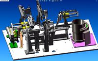
Electronic product assembly machine assembly machine
...electronic product assembly machine assembly machine
3dexport
electronic product assembly machine assembly machine
3d_export
$15
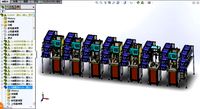
generator assembly line
...ced and assembled in the form of module block. it is a demonstration project of generator assembly. welcome to download and learn
3d_export
$10
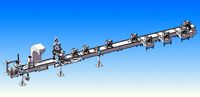
elevator traction machine assembly line motor assembly process
... traction machine assembly line motor assembly process
3dexport
elevator traction machine assembly line (motor assembly process)
3d_export
$16
pin assembly machine
...pin assembly machine
3dexport
pin assembly machine
3d_export
$7
tower-crane-assembly
...tower-crane-assembly
3dexport
tower-crane-assembly
turbosquid
$100

Engine Assembly
...id
royalty free 3d model engine assembly for download as stl on turbosquid: 3d models for games, architecture, videos. (1658296)
turbosquid
$100

Engine Assembly
...id
royalty free 3d model engine assembly for download as stl on turbosquid: 3d models for games, architecture, videos. (1658291)
turbosquid
$100

Engine Assembly
...id
royalty free 3d model engine assembly for download as stl on turbosquid: 3d models for games, architecture, videos. (1658293)
turbosquid
$75
Platform Assembly
...royalty free 3d model platform assembly for download as blend on turbosquid: 3d models for games, architecture, videos. (1472939)
turbosquid
$15
generator assembly
...y free 3d model generator assembly for download as and sldas on turbosquid: 3d models for games, architecture, videos. (1469469)