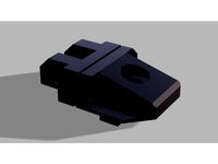
Thingiverse
I3 MK3 Clone (Haribo, Self-Sourced) by Achase79
by Thingiverse
Last crawled date: 3 years ago
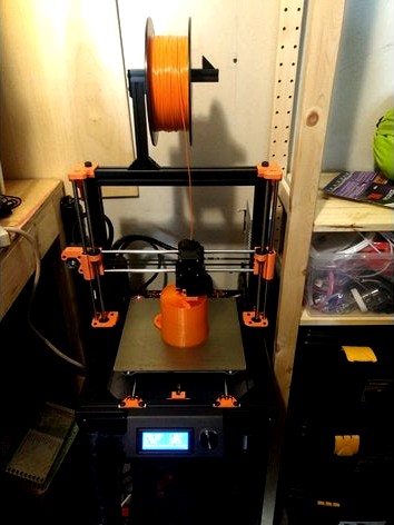
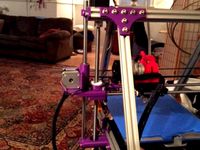
This is a self-sourced I3 MK3 Clone. It currently is a near-exact replica of an I3 MK3 Haribo, with the following deficiencies:
No Power Panic
The filament sensor is a standard IR optical sensor, not the PRUSA laser sensor.
It is likely that these parts will be cloned at some point (the power panic board could easily be cloned, but the sensors Prusa uses for the filament sensor are hard to come by.)
It runs a (slightly) modified PrusaFirmware 3.2.1 (for modified axis length, filament sensor). It passes X/Y/Z calibration, and everything works perfectly! The Haribo frame is also incredibly solid, especially with the power supply and Einsy case rigidly attached to the extrusions. It has been printing very reliably for the last month. I have filament runout detection working, although it can be a little sensitive to ambient light changes.
Honestly, if I did it again I would either just buy the MK3 or buy the MK2S->MK3 upgrade kit and add the haribo frame. This really isn't much cheaper. But it's very solid, prints wonderfully (I haven't had problems with the dreaded extrusion inconsistency issues), and was a fun project. It makes the most sense for someone who already has most of the parts and specifically wants a Haribo-style build.
BOM
[Haribo 3030 Extrusions] (https://github.com/PrusaMK2Users/3030_Haribo_Edition/tree/master/BOM). Also get the rubbed feet.
60 or so 3030 T-nuts. Add a few 3030 hammer nuts for post-install additions and tight spaces.
I got some black 3030 L-plates to stabilize the base (may not be necessary). These could easilly be printed.
3030 Feet
GT2 Belts and Pulleys
LM8UU bearings x 10
Y-carriage and U-bolts
Smooth Rods: X 370mm x 2, Y 350mm x 2, Z 320mm x 2.
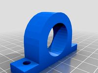
If you don't want to print the Prusa LCD holder, try this. New mounting holes need to be drilled, but it works (if you have rubber feet and the 3030 L bracket - bed clearance could be an issue if you don't have these).
The standard 2004 LCD smart controller display
Motors: Probably best to either get a set from Prusa or one that claims to be the same LDO motors (017 007 006 etc.). You want the same motors (especially on X and Y) if you're planning on using sensorless homing, since the thresholds are set for Prusa's high inductance motors, which will differ in other NEMA17 steppers.
Einsy Rambo (the Prusa version, not the retro version)
3 Pin 5V 5015 Blower. I used this one
Noctua or other 3 Pin 5V 40mm fan. I used this one
24V heatbed, Pinda 2 Probe (? and Prusa filament sensor) - best option is probably to buy the MK2S->MK3 upgrade kit from Prusa, but I bought a clone bed and Pinda 2 from 3dprintronics.com
Standard optical endstop (if you can't source the laser sensor). Its connector needs to be removed and replaced - you can either hack it off and solder directly to it or desolder and attach 90 degree header pins.
24V 17amp power supply if you don't get the Prusa MK2S->MK3 upgrade
Standard switched IEC inlet
Bondtech gears (real or cloned)
50 pcs M3 Square nuts (but see note below)
All necessary M3 screws (get list from Prusa build instructions)
50-60 PCS M6 12-14mm button-head hex screws
E3D V6 1.75 universal or bowden V6 clone (works in you unscrew the push-fit adapter)
If you want a spool holder, you can print one, use the Haribo one, or build one with 3 OpenBuilds black corner connectors, 2 ~120mm 2020 extrusions, and one small printed part.
Bag of Haribo gummies :)
A few notes:
Prusa uses M3 square nuts that are a little smaller/thinner than the typical Aliexpress ones. They can usually be fit in with a soldering iron/file/force, but get the smallest ones you can source, and some parts may need modification. If you read through the SCAD files in Prusa's github, you can see they are specing the square nuts as 2.1 x 5.6 x 5.6. The ones I found were 2.4 x 5.4 x 5.4. It takes a little force. Alternately, you can modify the SCADs and recompile them. [Update: Search specifically for DIN 562]
The standard Prusa fan shroud does slightly hit the Z-axis motors on homing, although it doesn't seem to cause any problems. I'm testing a narrower version of the shroud.
X/Y squaring requires a precise distance from the X-home to the first calibration point. What I did was leave the bed a little loose, watch it look for the calibration point, cancel, reposition the bed left/right and repeat. It took a couple of tries, but it worked.
X/Y/Z axis lengths are somewhat longer than on the original. Here are my settings:
X_MAX_POS 249
X_MIN_POS -6
Y_MAX_POS 232
Y_MIN_POS -4
Z_MAX_POS 210+28
Z_MIN_POS 0.15
If there's an interest in the optical endstop runout detection, I can post my hacky firmware. It seems to work, but has not been extensively thought out/tested.
No Power Panic
The filament sensor is a standard IR optical sensor, not the PRUSA laser sensor.
It is likely that these parts will be cloned at some point (the power panic board could easily be cloned, but the sensors Prusa uses for the filament sensor are hard to come by.)
It runs a (slightly) modified PrusaFirmware 3.2.1 (for modified axis length, filament sensor). It passes X/Y/Z calibration, and everything works perfectly! The Haribo frame is also incredibly solid, especially with the power supply and Einsy case rigidly attached to the extrusions. It has been printing very reliably for the last month. I have filament runout detection working, although it can be a little sensitive to ambient light changes.
Honestly, if I did it again I would either just buy the MK3 or buy the MK2S->MK3 upgrade kit and add the haribo frame. This really isn't much cheaper. But it's very solid, prints wonderfully (I haven't had problems with the dreaded extrusion inconsistency issues), and was a fun project. It makes the most sense for someone who already has most of the parts and specifically wants a Haribo-style build.
BOM
[Haribo 3030 Extrusions] (https://github.com/PrusaMK2Users/3030_Haribo_Edition/tree/master/BOM). Also get the rubbed feet.
60 or so 3030 T-nuts. Add a few 3030 hammer nuts for post-install additions and tight spaces.
I got some black 3030 L-plates to stabilize the base (may not be necessary). These could easilly be printed.
3030 Feet
GT2 Belts and Pulleys
LM8UU bearings x 10
Y-carriage and U-bolts
Smooth Rods: X 370mm x 2, Y 350mm x 2, Z 320mm x 2.
If you don't want to print the Prusa LCD holder, try this. New mounting holes need to be drilled, but it works (if you have rubber feet and the 3030 L bracket - bed clearance could be an issue if you don't have these).
The standard 2004 LCD smart controller display
Motors: Probably best to either get a set from Prusa or one that claims to be the same LDO motors (017 007 006 etc.). You want the same motors (especially on X and Y) if you're planning on using sensorless homing, since the thresholds are set for Prusa's high inductance motors, which will differ in other NEMA17 steppers.
Einsy Rambo (the Prusa version, not the retro version)
3 Pin 5V 5015 Blower. I used this one
Noctua or other 3 Pin 5V 40mm fan. I used this one
24V heatbed, Pinda 2 Probe (? and Prusa filament sensor) - best option is probably to buy the MK2S->MK3 upgrade kit from Prusa, but I bought a clone bed and Pinda 2 from 3dprintronics.com
Standard optical endstop (if you can't source the laser sensor). Its connector needs to be removed and replaced - you can either hack it off and solder directly to it or desolder and attach 90 degree header pins.
24V 17amp power supply if you don't get the Prusa MK2S->MK3 upgrade
Standard switched IEC inlet
Bondtech gears (real or cloned)
50 pcs M3 Square nuts (but see note below)
All necessary M3 screws (get list from Prusa build instructions)
50-60 PCS M6 12-14mm button-head hex screws
E3D V6 1.75 universal or bowden V6 clone (works in you unscrew the push-fit adapter)
If you want a spool holder, you can print one, use the Haribo one, or build one with 3 OpenBuilds black corner connectors, 2 ~120mm 2020 extrusions, and one small printed part.
Bag of Haribo gummies :)
A few notes:
Prusa uses M3 square nuts that are a little smaller/thinner than the typical Aliexpress ones. They can usually be fit in with a soldering iron/file/force, but get the smallest ones you can source, and some parts may need modification. If you read through the SCAD files in Prusa's github, you can see they are specing the square nuts as 2.1 x 5.6 x 5.6. The ones I found were 2.4 x 5.4 x 5.4. It takes a little force. Alternately, you can modify the SCADs and recompile them. [Update: Search specifically for DIN 562]
The standard Prusa fan shroud does slightly hit the Z-axis motors on homing, although it doesn't seem to cause any problems. I'm testing a narrower version of the shroud.
X/Y squaring requires a precise distance from the X-home to the first calibration point. What I did was leave the bed a little loose, watch it look for the calibration point, cancel, reposition the bed left/right and repeat. It took a couple of tries, but it worked.
X/Y/Z axis lengths are somewhat longer than on the original. Here are my settings:
X_MAX_POS 249
X_MIN_POS -6
Y_MAX_POS 232
Y_MIN_POS -4
Z_MAX_POS 210+28
Z_MIN_POS 0.15
If there's an interest in the optical endstop runout detection, I can post my hacky firmware. It seems to work, but has not been extensively thought out/tested.
Similar models
thingiverse
free
Prusa MK2 Haribo 3030 Y Belt Tensioner by IsmaelPR1
...ustom supports in the space where the square nut will sit using s3d, not sure if you can print without supports it give it a try.
thingiverse
free

Custom Y Motor Mount for Mk 3 3030 Haribo by Olef
...mounting for rigidity. fits 3030 extrusion.
(remixed from mattyvee's reinforced 3 bolt y axis motor mount for prusa i3 mk3)
thingiverse
free

Haribo 3030 Prusa MK3 Upgrade double PSU Meanwell RSP by thunder_88
...to "shorten" the y-axis a bit. i printed a 1 cm long part for "shortening" the y-axis. check out the picture!
thingiverse
free
Filament holder for 3030 aluminum frames by jadam
... these holders are based on measurements of the prusa filament holders with a new bottom end that clips into the 3030 extrusion.
thingiverse
free

Ribbon holder for 3030 Extrusion (Prusa MK3, Zaribo and Haribo) by mimisb13
...ribbon holder for 3030 extrusion (prusa mk3, zaribo and haribo) by mimisb13
thingiverse
ribbon clip for 3030 extrusion
thingiverse
free
Haribo 3030 Z-Motor Mounts by Chileo
...n print the mount without any supports, for this, the upper srew hole closed on one side. you have to cut or drill the hole open.
thingiverse
free
T-nut M6 (HNTTSN6-6) for 3030 extrusion profile by marciomarciano
...steel nut based on misumi part #hnttsn6-6 specifications. was on a budget when building my prusa mk2 haribo edition (3030 frame).
thingiverse
free
MK2-X Y-Axis with Damper & 3030 T-Nut by mshavell
... is for the mk2-x rebuild of the prusa i3.
the original part is incompatible with m6 3030 12mm t-nuts due to the channel guide.
thingiverse
free
Drop-in M5 T-nut for 3030 by adrianishikawa
...for 2020s, that or are not drop-in designs.
thus i followed some generic design of a drop-in t-nut and designed it in solidworks.
thingiverse
free

Prusa i3 MK2-X 16mm T-Nut Support by Kaluriel
...a arm to support the motor a bit more.
i haven't printed them yet to test but they should have a 16mm gap for the square nut.
Achase79
thingiverse
free

Guatemala Pig by Achase79
... pig i bought in guatemala. it has a drawer which pulls out of its side.
http://youtu.be/mjcwqyym3qkhttp://youtu.be/j71ris9ma1y
thingiverse
free
12mm rod holder mounts w/ M5 SHSC by Achase79
... has a 13mm bore with a m5 compression bolt to bring it down to < 12mm, m5 screw holes to mount to 2020 extrusion or whatever.
thingiverse
free
608zz pillow block mount (same footprint as KP08) by Achase79
...xtra rigidity, you can just about fit 2 608zz bearings inside, since the kp08 footprint is 13mm wide and the 608zzs are 7mm wide.
thingiverse
free

Alumimaker 2 by Achase79
...za
i posted a bom and some more description here: http://www.reddit.com/r/3dprinting/comments/2rzjwc/misumi_usa_contest/cob4802
thingiverse
free
Modifications for Bind-Reducing X-ends with Makers Tool Works Leadscrews For MendelMax and 10mm Rods by Achase79
...th upper motor mounts in my mendelmax 2, so i thought i'd give it a try, and it works pretty well with the aluminum couplers.
Haribo
thingiverse
free
Haribo (With a Heart) by somethingc
... a heart)
remixed for da vinci jr (and given a heart)
https://www.etsy.com/uk/listing/399004331/haribo-with-a-heart-voronoi-style
thingiverse
free
Orange Pi Haribo 3030 by MrJean
...orange pi haribo 3030 by mrjean
thingiverse
a remix for my haribo printer , 3030 aluminum
thingiverse
free

Haribo Bike Bear by DRNXIII
...rnxiii
thingiverse
modified the gummy bear model to have a hole in the bottom, so i can be fixed on a puky haribo bike for kids.
thingiverse
free
Haribo mod Titan/Mk8 extruder mount by anraf1001
...haribo mod titan/mk8 extruder mount by anraf1001
thingiverse
an extruder mount for haribo mod.
thingiverse
free
haribo/zaribo y idler holder by NeoFromMatrix
...zaribo y idler holder by neofrommatrix
thingiverse
y idler holder for haribo/zaribo (30x30mm aluminium extrusion with 8mm slots)
thingiverse
free

Secret Haribo Box (remix) by jonasrh
...changed the top and the side parts. download the rest of the files from the original boxhttps://www.thingiverse.com/thing:2977908
thingiverse
free
3030 Extrusion and Haribo Filament Guide by MIKEYMCC
...layer height with suppport enabled in petg.
update: added a new version of the filament guide. the other is too low for a haribo.
thingiverse
free
Spool Holder for 3030 Haribo Prusa i3 by MarcoZ76
... for 3030 haribo prusa i3 by marcoz76
thingiverse
spool holder for prusa i3 haribo 3030 modification. you need a 8 mm rod steel
thingiverse
free

Haribo 3030 Filament holder by nonads69
...have added an updated set of holders that are for a 6.3mm gap in the extrusion, these are labelled as 6-3mm in their description.
thingiverse
free
3030 Y Belt tensioner for Haribo / Zaribo by Stwebster
... for the haribo or zaribo mod.
you have to remove the support material from the bottom.
the file for fusion 360 is also included.
Mk3
turbosquid
$50

cention mk3
...ty free 3d model cention mk3 for download as ma, obj, and fbx on turbosquid: 3d models for games, architecture, videos. (1454148)
turbosquid
$129
MK3 Tank
... available on turbo squid, the world's leading provider of digital 3d models for visualization, films, television, and games.
turbosquid
$100

Toyota Supra MK3
... available on turbo squid, the world's leading provider of digital 3d models for visualization, films, television, and games.
turbosquid
$44

cention mk3 low poly
...d model cention mk3 low poly for download as ma, obj, and fbx on turbosquid: 3d models for games, architecture, videos. (1454666)
turbosquid
$30

Challenger I Mk3 Falcon
... available on turbo squid, the world's leading provider of digital 3d models for visualization, films, television, and games.
turbosquid
$10

American Frag hand grenade MK3
...free 3d model american frag hand grenade mk3 for download as on turbosquid: 3d models for games, architecture, videos. (1393624)
turbosquid
$20
Mk3 US Navy Combat Knife
...ty free 3d model mk3 us navy combat knife for download as fbx on turbosquid: 3d models for games, architecture, videos. (1172791)
3d_export
$29

Ford Fiesta MK3 Modified 3D Model
...7 tumerfx mtumer mehmet t?mer 1993 1995 1996 wrc special modifed modifiye
ford fiesta mk3 modified 3d model mtumer 30698 3dexport
3d_export
$99

Toyota Supra Mk3 19861993 3D Model
...ort fast coupe japan 1986 1987 1988 1989 1990 1991 1992 1993 tuning turbo
toyota supra mk3 19861993 3d model squir 62530 3dexport
turbosquid
$5

Timothy Oulton Mars Chair MK3
...on mars chair mk3 for download as 3ds, max, obj, fbx, and dae on turbosquid: 3d models for games, architecture, videos. (1209782)
Self
3ddd
$1
Self
... банкетка
каталог minotti 2010модель selfдизайнер rodolfo dordoniш\д\в 60\120\42
3ddd
$1

Minotti Self
...minotti self
3ddd
minotti
банкетка minotti self
3ddd
$1
Minotti Self
...minotti self
3ddd
minotti , self
текстуры и материалы прилагаются.
3ddd
$1
Self cleaning ashtrays
...self cleaning ashtrays
3ddd
пепельница
self cleaning ashtrays
turbosquid
$15

Book self
...
royalty free 3d model book self for download as max and fbx on turbosquid: 3d models for games, architecture, videos. (1502520)
3d_export
free
self-tapping screw
...self-tapping screw
3dexport
self-tapping screw 55 мм
turbosquid
$12

Book Self
...lty free 3d model book self for download as max, obj, and fbx on turbosquid: 3d models for games, architecture, videos. (1473695)
turbosquid
$4

Self with Desk
...d model self with desk for download as 3ds, max, obj, and fbx on turbosquid: 3d models for games, architecture, videos. (1511139)
turbosquid
$2

Book Self
...ree 3d model book self for download as max, fbx, 3ds, and obj on turbosquid: 3d models for games, architecture, videos. (1544366)
turbosquid
$2

Book self
...ree 3d model book self for download as 3ds, max, fbx, and dwg on turbosquid: 3d models for games, architecture, videos. (1300384)
I3
3d_export
$10
suv i3
...suv i3
3dexport
suv i3 2013 series
3d_ocean
$89

BMW i3 2012
...y, in real units of measurement, qualitatively and maximally close to the original. model formats: - *.max (3ds max 2008 scanl...
cg_studio
$99

BMW i3 20143d model
...
cgstudio
.3ds .c4d .fbx .lwo .max .obj - bmw i3 2014 3d model, royalty free license available, instant download after purchase.
cg_studio
$99

BMW i3 20123d model
...tudio
.3ds .c4d .fbx .lwo .max .mb .obj - bmw i3 2012 3d model, royalty free license available, instant download after purchase.
cg_studio
$99

BMW i3 20143d model
...tudio
.3ds .c4d .fbx .lwo .max .mb .obj - bmw i3 2014 3d model, royalty free license available, instant download after purchase.
humster3d
$75

3D model of BMW i3 2014
...
buy a detailed 3d model of bmw i3 2014 in various file formats. all our 3d models were created maximally close to the original.
humster3d
$40

3D model of Kitchen Set I3
...uy a detailed 3d model of kitchen set i3 in various file formats. all our 3d models were created maximally close to the original.
3d_ocean
$30
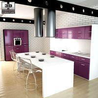
Kitchen set i3
...ensils oven plates shelves sink table ware
kitchen set i3 include 3d models: cooker, oven, sink, cupboards, table, chair, plates.
3d_ocean
$89

BMW i3 2014
...y, in real units of measurement, qualitatively and maximally close to the original. model formats: - *.max (3ds max 2008 scanl...
cg_studio
$99

BMW i3 Concept 20113d model
...i3
.3ds .c4d .fbx .lwo .max .obj - bmw i3 concept 2011 3d model, royalty free license available, instant download after purchase.
Clone
3d_export
$5
Clones great republic
...clones great republic
3dexport
clones great republic.those same clones from the star wars movie universe.4 clones available.
3d_export
$10

Clone 3D Model
...clone 3d model
3dexport
clone woman girl female lady chamber sci fi
clone 3d model calcm1 51695 3dexport
turbosquid
$5

Clone machine
... available on turbo squid, the world's leading provider of digital 3d models for visualization, films, television, and games.
archive3d
free

Clone trooper 3D Model
...nd army soldier trooper
clone trooper 2 - 3d model (*.gsm+*.3ds) for interior 3d visualization.
turbosquid
free

Lego Clone Walker
...ree 3d model lego sw clone walker for download as max and fbx on turbosquid: 3d models for games, architecture, videos. (1292252)
turbosquid
$15

Clone trooper helmet
...d model clone trooper helmet for download as ma, obj, and fbx on turbosquid: 3d models for games, architecture, videos. (1199355)
archive3d
free

Clone trooper 3D Model
...and army soldier trooper
clonetrooper 3 - 3d model (*.gsm+*.3ds) for interior 3d visualization.
archive3d
free

Clone trooper 3D Model
...and army soldier trooper
clonetrooper 1 - 3d model (*.gsm+*.3ds) for interior 3d visualization.
3d_ocean
$35

Surface Clone C4D materials
...+ of the most well made materials for maxon’s cinema 4d; on the internet today. each material is crafted with a specific purpo...
turbosquid
$3

Sci-fi cloning vats
...cloning vats for download as 3ds, obj, wrl, x, fbx, and blend on turbosquid: 3d models for games, architecture, videos. (1290168)
Sourced
turbosquid
$30

source
...e
turbosquid
royalty free 3d model source for download as ma on turbosquid: 3d models for games, architecture, videos. (1154551)
3d_export
$7

Source
...er software such as blender, 3d max, unity in the preview you will see the model with its respective materials, textures and mesh
design_connected
$13

Master Line Source
...master line source
designconnected
piega master line source computer generated 3d model.
3ddd
$1

SodaStream Source
...sodastream source
3ddd
сифон
designed by yves béhar
сифон компании sourcestream, изготовленный в современном стиле
turbosquid
$199

Demon source files
... available on turbo squid, the world's leading provider of digital 3d models for visualization, films, television, and games.
turbosquid
$99

Water Source Animation
... available on turbo squid, the world's leading provider of digital 3d models for visualization, films, television, and games.
turbosquid
$20

THEATRICAL LIGHT - SOURCE 4
... available on turbo squid, the world's leading provider of digital 3d models for visualization, films, television, and games.
turbosquid
$15

Cross 3D print source model
... 3d print source model for download as max, max, obj, and stl on turbosquid: 3d models for games, architecture, videos. (1680597)
turbosquid
$22
Column capital source 3dsMax 001
...smax 001 3d model for download as max, max, max, obj, and stl on turbosquid: 3d models for games, architecture, videos. (1683199)
3ddd
free

Lite Source LS-21155C-WHT Table Lamps
...le lamps
3ddd
lite source
http://www.lamps-lighting.com/lite-source/ls-21155c-wht.html
3dsmax 2013+2010+obj+.fbx+.3ds