Thingiverse
Hydraulic Robot Arm 6-Axis by Blastronauticus
by Thingiverse
Last crawled date: 3 years ago
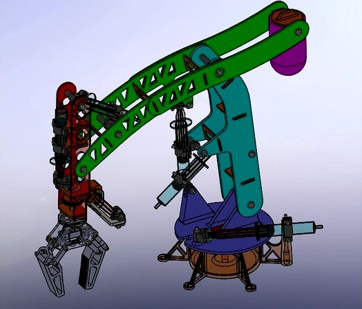
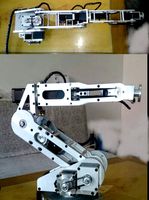
This is a 6-axis hydraulic "robot" arm. The axes are actuated with 10ml syringes which act as cylinders, and 1/8" inside diameter flexible tubing. I saw a few versions of these on social media, mostly made out of cardboard or kits with laser cut wood. I thought it would be cool to make my own with printed parts.
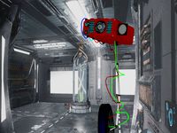
As you can see below, getting this thing to work was a process. I've added a counterweight (fill with sand) to help it hold position a little better, but it's not perfect. All 6 axes are functional, but it doesn't always hold position very well. Redesigning the controller to be self locking somehow would be ideal, but I just don't have time right now.
UPDATE 3/2/20 I've added STEP files for the arm and the controller, with an improved version of the base in it. I don't know when I'll get around to making more improvements, but feel free to take the step files and do a remix.
Update 11/4/2018 I fully assembled and tested the arm today. It does work but the weight of the gripper pulls the arm down if you let go of certain levers, depending on the position. I have a few ideas of how to fix this, including adding a counterweight to the arm, screwing the base and controller to a board (I also filled the base with pebbles for counterweight), and possibly re-designing the controller and adding valves to some of the axes for parking. All of this will take time to develop, and I'll keep it set to "work in progress" until I'm satisfied with it. Aside from the weight issue there weren't many other hang ups. Some of the holes were a bit tight and I just widened them out a bit with a drill bit. You can only access 4 of the 6 screws for the wrist, but 4 is plenty.
Update 10/26/18 I've ordered all the fasteners so I should have this thing built and tested sometime in early November. I'm going to give it a shot using 4mm wooden dowels instead of the M4 bolts, but I still had to buy all of the M3 stuff and the M4 threaded rod from the hardware list. I'm going to add printed retainers for the dowels and add an STL to print the large m4 washers for the pivot points on the arm linkages.
Update 10/8/18 I'm finished with the modeling and I'm starting to print parts. I've uploaded an STL of the entire assembly for reference to give you an idea of how it assembles. I have uploaded all the STL files, but I'm going to keep this as a "work in progress" until I have completely assembled and tested it. Files may change so print at your own risk. I've included a hardware list in an excel sheet as well. After I get it assembled I will consider doing different options for the gripper, including offset claws for grabbing larger objects.
Notes: (refer to PDF drawing for more details)
My syringes measure 16.5mm diameter with the outer section around 94mm long from end to end. The plunger sticks out 17.5mm from the end of the syringe when fully pressed in, and they have about a 55mm stroke length at 10ml. Yours may vary a bit. Hit me up in the comments if you need a custom part to finish the assembly.
You will need to adjust where each syringe is clamped at to get the optimum movement of the arm. The PDF drawing shows where to clamp them at.
Only use about 7-8ml of water in the wrist rotation syringe, otherwise it will crash the gear into the end of the rack. You should get at least a full 180 degrees of rotation.
The gripper syringe should only be filled about 3ml.
All the other syringes use 10ml of water. Might be able to add a bit extra to get a longer stroke on some of them.
Mostly all of the m4 bolts and the m3 bolts on the gripper links need to be a little loose so things can move. I recommend using nylon lock nuts in these locations. See the included hardware list spreadsheet for quantities.
The tabs for the frame pieces fit together tightly and permanently. You may need to clean up the edges a bit to get them to press together. I made an effort to idiot proof the tabs so you can't put the wrong ones in, but pay attention and make sure they are in the correct position before pressing them together.
Hardware for this will cost you a bit. I was able to find everything in the U.S. from Fastenal's website, for about $31.00 USD plus shipping. You might need to round up on the screw lengths depending on what you can find available. There's a hardware list excel sheet in the files for this thing. You could use 4mm wooden dowels for some of the fasteners to save money and glue on some sort of end caps. I would recommend using screws for the M3 fasteners though.
I've included instructions in the hardware list for using 4mm wooden dowel rods instead of most of the M4 hardware. This should help keep cost down a bit. You'll need to print 56 of the 4mm_retainer parts to do this.
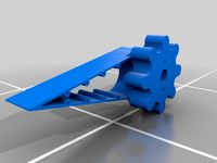
For the rack and gear I would recommend printing them individually at slow speeds, and consider a smaller nozzle. I used a 0.2mm nozzle and 30mm/s for the outer wall speed, but 0.3mm or 0.4mm might be ok.
As you can see below, getting this thing to work was a process. I've added a counterweight (fill with sand) to help it hold position a little better, but it's not perfect. All 6 axes are functional, but it doesn't always hold position very well. Redesigning the controller to be self locking somehow would be ideal, but I just don't have time right now.
UPDATE 3/2/20 I've added STEP files for the arm and the controller, with an improved version of the base in it. I don't know when I'll get around to making more improvements, but feel free to take the step files and do a remix.
Update 11/4/2018 I fully assembled and tested the arm today. It does work but the weight of the gripper pulls the arm down if you let go of certain levers, depending on the position. I have a few ideas of how to fix this, including adding a counterweight to the arm, screwing the base and controller to a board (I also filled the base with pebbles for counterweight), and possibly re-designing the controller and adding valves to some of the axes for parking. All of this will take time to develop, and I'll keep it set to "work in progress" until I'm satisfied with it. Aside from the weight issue there weren't many other hang ups. Some of the holes were a bit tight and I just widened them out a bit with a drill bit. You can only access 4 of the 6 screws for the wrist, but 4 is plenty.
Update 10/26/18 I've ordered all the fasteners so I should have this thing built and tested sometime in early November. I'm going to give it a shot using 4mm wooden dowels instead of the M4 bolts, but I still had to buy all of the M3 stuff and the M4 threaded rod from the hardware list. I'm going to add printed retainers for the dowels and add an STL to print the large m4 washers for the pivot points on the arm linkages.
Update 10/8/18 I'm finished with the modeling and I'm starting to print parts. I've uploaded an STL of the entire assembly for reference to give you an idea of how it assembles. I have uploaded all the STL files, but I'm going to keep this as a "work in progress" until I have completely assembled and tested it. Files may change so print at your own risk. I've included a hardware list in an excel sheet as well. After I get it assembled I will consider doing different options for the gripper, including offset claws for grabbing larger objects.
Notes: (refer to PDF drawing for more details)
My syringes measure 16.5mm diameter with the outer section around 94mm long from end to end. The plunger sticks out 17.5mm from the end of the syringe when fully pressed in, and they have about a 55mm stroke length at 10ml. Yours may vary a bit. Hit me up in the comments if you need a custom part to finish the assembly.
You will need to adjust where each syringe is clamped at to get the optimum movement of the arm. The PDF drawing shows where to clamp them at.
Only use about 7-8ml of water in the wrist rotation syringe, otherwise it will crash the gear into the end of the rack. You should get at least a full 180 degrees of rotation.
The gripper syringe should only be filled about 3ml.
All the other syringes use 10ml of water. Might be able to add a bit extra to get a longer stroke on some of them.
Mostly all of the m4 bolts and the m3 bolts on the gripper links need to be a little loose so things can move. I recommend using nylon lock nuts in these locations. See the included hardware list spreadsheet for quantities.
The tabs for the frame pieces fit together tightly and permanently. You may need to clean up the edges a bit to get them to press together. I made an effort to idiot proof the tabs so you can't put the wrong ones in, but pay attention and make sure they are in the correct position before pressing them together.
Hardware for this will cost you a bit. I was able to find everything in the U.S. from Fastenal's website, for about $31.00 USD plus shipping. You might need to round up on the screw lengths depending on what you can find available. There's a hardware list excel sheet in the files for this thing. You could use 4mm wooden dowels for some of the fasteners to save money and glue on some sort of end caps. I would recommend using screws for the M3 fasteners though.
I've included instructions in the hardware list for using 4mm wooden dowel rods instead of most of the M4 hardware. This should help keep cost down a bit. You'll need to print 56 of the 4mm_retainer parts to do this.
For the rack and gear I would recommend printing them individually at slow speeds, and consider a smaller nozzle. I used a 0.2mm nozzle and 30mm/s for the outer wall speed, but 0.3mm or 0.4mm might be ok.
Similar models
thingiverse
free

Hydraulic Robot Arm w/10ml Syringes by bmscott
...nt...
the working files are on tinkercad at https://www.tinkercad.com/things/8wsfrhsj9gx-hydraulic-robot-arm-syringe-housing-10ml
thingiverse
free

Spool Holder by TechnoSwiss
... the bin i was pulling them from at the hardware store. i think their bin is mis-labeled, as i get 5/8" when i measure them.
thingiverse
free

Hydraulic Powered Robotic Arm by MrBoyle
...ew rubber bands.
for tubing i suggest an airline tubing that is relatively stiff. flexible tubing doesn't work quite as well.
thingiverse
free

10Ml syringe adapter by fosstob
...'s "simple-paste-extruder", so i created a simple adapter to use the 10ml syringes given out by our local pharmacy.
thingiverse
free
Locking ball and socket arm - Print and Assembly Optimized by KriLL3
... them stay where you put them instead of sagging over time. i'll adapt the end pieces of thing to use the locking rings soon.
thingiverse
free

10ml Syringe Lock by userexec
...isn't the internet great?
printed on an sla printer, but should work fine on a cartesian as well at 100% infill for strength.
thingiverse
free

Spool Holder by ya3dpc
...e included them for your use if you would like them.
oh and i printed the arm on its side. but i think it'll work either way.
thingiverse
free

IKEA Spare Part No. 3 "Dowel" by MakerBot_Europe
...wel". i guess everybody knows that you always need them the most when you can't get them, so why not just 3d-print them?
thingiverse
free

Syringe Holder (6) 14mm Barrel, 10mL by anjilus
...aid down (50ml).
ended up i needed more to be held, so i designed a 9 syringe holder which you can find under the search as well.
thingiverse
free
Adaptive Gripper v2 by zmaker1
... print out two grippers (one left and one right). other parts include a pixy camera, paperclips, and a dowel (i use a steel one).
Blastronauticus
thingiverse
free
Toyota Rav4 roof rack key by Blastronauticus
... face with the keyed profile on it.
i used petg but pla would be fine, just don't leave it in a hot car or it'll deform.
thingiverse
free

Enterprise D 1:2000 model display stand by Blastronauticus
...chbox wood pla, which required me to use a 0.6mm nozzle, so some of the finer details of the federation emblem were lost. engage.
thingiverse
free
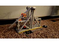
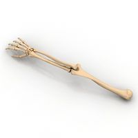
F2K Trebuchet by Blastronauticus
...end of the arm, the other is attached to a small washer that goes around the pin on the end of the arm. you'll figure it out.
Hydraulic
3d_ocean
$8
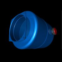
hydraulic tank
...hydraulic tank
3docean
hydraulic tank
hydraulic tank
3d_export
$7
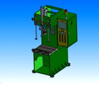
5t hydraulic press
...5t hydraulic press
3dexport
5t hydraulic press
3d_export
$6

e15 hydraulic station
...e15 hydraulic station
3dexport
e15 hydraulic station
3d_export
$45

hydraulic excavator
...excavator
3dexport
3d model excavator.blender 2.93. hight polygon. hydraulic excavator model with pbr textures. .obj .fbx .blend
turbosquid
$90

Hydraulic pump
...d
royalty free 3d model hydraulic pump for download as sldas on turbosquid: 3d models for games, architecture, videos. (1245128)
turbosquid
$1

Hydraulic Cylinder
...oyalty free 3d model hydraulic cylinder for download as blend on turbosquid: 3d models for games, architecture, videos. (1515778)
turbosquid
$5
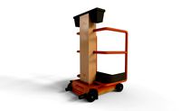
Hydraulic Lift
...alty free 3d model hydraulic lift for download as obj and fbx on turbosquid: 3d models for games, architecture, videos. (1443188)
turbosquid
$20

Hydraulic jack
...d model hydraulic jack for download as c4d, fbx, dae, and obj on turbosquid: 3d models for games, architecture, videos. (1699409)
turbosquid
$49

Platform Hydraulic
... available on turbo squid, the world's leading provider of digital 3d models for visualization, films, television, and games.
turbosquid
$39
Hydraulic Jack
... available on turbo squid, the world's leading provider of digital 3d models for visualization, films, television, and games.
Axis
3ddd
$1

Мария Axis
...
3ddd
кухня , классическая , axis
модель кухни.
3d_export
$22
Axis robot 6-axis robotic arm
...ing parts drawings, standard parts purchased parts list, can be produced directly according to the drawings, welcome to download!
3ddd
free

Versatile Axis
...ddd
nexus , плитка
http://bvtileandstone.com/ceramic-porcelain/versatile-axis/
3d_export
$19
robot 2 axis
...robot 2 axis
3dexport
robot 2 axis
turbosquid
$40
Axis R5F
... available on turbo squid, the world's leading provider of digital 3d models for visualization, films, television, and games.
turbosquid
$40
Axis S5F
... available on turbo squid, the world's leading provider of digital 3d models for visualization, films, television, and games.
turbosquid
$30
Axis Athlon
... available on turbo squid, the world's leading provider of digital 3d models for visualization, films, television, and games.
turbosquid
$10

Linear Axis
... available on turbo squid, the world's leading provider of digital 3d models for visualization, films, television, and games.
3d_export
$15

drawing axis
...drawing axis
3dexport
simple rendering of the scene file
3ddd
$1

versatile axis ARC
...versatile axis arc
3ddd
versatile , плитка
versatile axis arc red dot design award
Robot
3d_ocean
$20

Robot
...robot
3docean
character metal robot robot robotic white
robot model for 3dsmax 2009 and greater
3d_ocean
$45
Robot
...robot
3docean
fighing machine robot
a fighting robot from the scrapyard.
3d_ocean
$18
Robot
...robot
3docean
machin robot science fiction
high poly robot.
3d_export
$7
Robot
...robot
3dexport
robot
3d_export
$5
robot
...robot
3dexport
robot
3d_export
free

Robot
...robot
3dexport
robot
turbosquid
$10

Robot/ Alien Robot
...
royalty free 3d model robot/ alien robot for download as max on turbosquid: 3d models for games, architecture, videos. (1442828)
3d_export
$5

robot
...robot
3dexport
robot in blender
3ddd
$1
robot
...robot
3ddd
робот
robot
3ddd
$1

Robot
...robot
3ddd
робот
robot
Arm
archibase_planet
free
Arm
...ase planet
arm hand right hand skeleton
arm human skeleton right arm n030515 - 3d model (*.gsm+*.3ds+*.max) for 3d visualization.
3ddd
$1

arm chair
...arm chair
3ddd
arm chair , пуф
arm chair
turbosquid
$5
arm
...arm
turbosquid
royalty free 3d model arm for download as obj on turbosquid: 3d models for games, architecture, videos. (1306158)
turbosquid
free

Arm
...arm
turbosquid
free 3d model arm for download as obj and fbx on turbosquid: 3d models for games, architecture, videos. (1346955)
turbosquid
$29

Arm
...osquid
royalty free 3d model arm for download as obj and fbx on turbosquid: 3d models for games, architecture, videos. (1382436)
3d_export
$5

coat of arms
...coat of arms
3dexport
coat of arms
3ddd
$1
ARM SOFA
...arm sofa
3ddd
arm sofa
3ddd
$1

Arm chair
...arm chair
3ddd
arm chair
3ddd
$1

Arm chair
...arm chair
3ddd
угловое
arm chair
3ddd
$1
ARM CHAIR
...arm chair
3ddd
arm chair clothes
6
3d_export
$18

tulip 6
...tulip 6
3dexport
tulip 6
3d_export
$5
hinge 6
...hinge 6
3dexport
hinge 6
3ddd
$1
MASIERO / FLASHWOOD STL 6 + 6
...6
3ddd
masiero
торшер flashwood stl 6 + 6 фабрики masiero
http://www.masierogroup.com/c87_697/it/flashwood%20stl%206%20+%206.ashx
turbosquid
$110

Atmos Cannon 2000 6*6
...yalty free 3d model atmos cannon 2000 6*6 for download as skp on turbosquid: 3d models for games, architecture, videos. (1528591)
turbosquid
$1
ae 6 6 electric locomotive
... free 3d model ae 6 6 electric locomotive for download as obj on turbosquid: 3d models for games, architecture, videos. (1707537)
turbosquid
$39
A-6
... available on turbo squid, the world's leading provider of digital 3d models for visualization, films, television, and games.
3ddd
$1
6 ковров
...6 ковров
3ddd
ковры , ковер
6 ковров
turbosquid
$12

Calligraphic Digit 6 Number 6
...hic digit 6 number 6 for download as max, obj, fbx, and blend on turbosquid: 3d models for games, architecture, videos. (1389336)
turbosquid
$19

Case For Phone 6 Girl 6
... available on turbo squid, the world's leading provider of digital 3d models for visualization, films, television, and games.
turbosquid
$35

Iphone 6 & 6 Plus All
... available on turbo squid, the world's leading provider of digital 3d models for visualization, films, television, and games.