Thingiverse
Hybrid Darrieus Helix Rotor by menzenbach
by Thingiverse
Last crawled date: 3 years ago
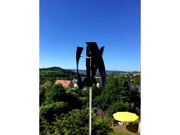
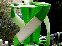
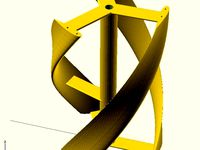
This is a Darrieus wind generator, which optionally can be extended with Savonius blades to a hybrid rotor.
The Savonius extension is very useful, since the Darrieus rotor has problems to start.
Take care that also vertical wind turbines require protection in case of strong winds.
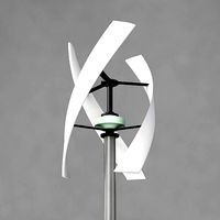
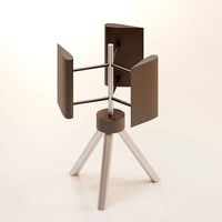
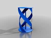
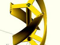
Rotor
The rotor consists out of 3 NACA 0015 airfoils, which are extruded as helix with 4 parts each and an overall height of 80 cm.
Each of the 3 middle part of the helix blade requires the parts "helix blade" and "helix blade 2" clued together. I made good experience with 2-component adhesive with 5 minutes hardening, since it is difficult to fix the two pieces for a long time.
The blades are finally mounted to the blade holder with aluminium tubes with a length of 222 mm each. The drill tool helps to drill the holes with the right distance. Print 2 drill tools and put them over the tube. The distance of the hole center to the end of the tube is 20 mm on one side and 17 mm on the other side.
A collar fixes the two blade holders with the 20 mm shaft. Use 2-component adhesive to clue the collar with the blade holder. Take care that the headless screw of the collar fits into the small hole of the blade holder.
The blades are printed with PETG and 15% infill only to keep the blades as light as possible. 5 top- and bottom layers and 0.2 mm layer height. Support is useful for the pickups. PLA should work as well.
There are 2 versions of the helix blade, mid and large. I recommend to use the mid version, because of lower weight and it requires less filament. Update Feb. 12 2018
I added a new blade to increase the radius of the rotor by 100 mm. Hence the length of the aluminium tubes is 322 mm. The 2 modifiers allow to reduce the overall weight of the rotor. The blades are printed with 2 perimeter only and 5% infill density. The modifiers with 20% infill density. With this, the weight of the blade part is reduced to less then 150 g.
Learn more about using modifiers in this blog: http://slic3r.org/blog/modifier-meshes
The blade_end_mid can also be used for this blade.
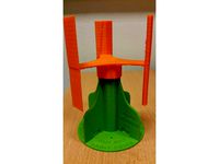
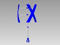
Generator
The air-cor coil generator is applying a Halbach array in order to get the best performance. The principles of the Halbach array can be found here: https://en.wikipedia.org/wiki/Halbach_array
For the stator coils I used copper wire with 0.75 mm diameter. I managed to coil up 35 turns per coil. Each phase has 8 coils which are connected in series. Use the coil tool to keep the area in front of the holes in the middle of the coil clear. 4 for the 1st phase and 2 for the 2nd phase.
I used cable ties to fix the wires of the coils. After all coiling up was finished, the hole stator was additionally fixed with spar varnish.
With moderate winds the generator delivers about 3.5 Volt AC per phase. Use a 3 phase rectifier followed by a DC-DC step up converter in order to achieve > 14 V as input to the battery charger. Take care that the step up converter is operating from 3 V onward. With stronger wind, like in the second video, the generator delivers more then 10 V AC. Due to the high wire cross section, the current is sufficient to supply the step up converter for high output power.
The weight of the rotor leads to the axial forces. Therefore I am using a roller bearing at the bottom of the generator. Roller bearings and ball bearings have different thickness. Hence the distance rings between the bearing and the rotor are also different. Of course it is also possible to use 2 roller bearings, but I am assuming they have a slightly higher resistance.
A collar fixes the rotor with the 20 mm shaft. Use 2-component adhesive to clue the collar with the rotor. Take care that the headless screw of the collar fits into the hole of the rotor.
All parts of the generator are printed with PETG and 25% infill. Update Apr. 29 2018
A new part "nipple" was added to protect the generator from water intrusion. Clue this on top of the upper cover. Update March 15 2019
It appears that the step-up converter generates a high load already at 3V. This prevents that the rotor reaches an efficient operation point. In order to avoid this, a threshold switch (about 6 V) should be inserted in the input line of the step up converter. Alternatively a voltage doubler as shown here https://www.mikrocontroller.net/attachment/93313/Verdreifacher_3-Phasig.png could be used. Or simply a wind MPTT charge controller with boost function.
Rod
I used a 40 x 3 mm Aluminium rod, but with 2 m length this one is oscillating until the rotor has reached a certain speed. Hence I recommend to use a 40 x 5 mm rod.
Here some videos:
Moderate wind: https://youtu.be/QC80Ev-aL6k
Stronger wind: https://youtu.be/cp6HL0YoWEE
350mm radius: https://youtu.be/cXBZ0u_D9mc
The Savonius extension is very useful, since the Darrieus rotor has problems to start.
Take care that also vertical wind turbines require protection in case of strong winds.
Rotor
The rotor consists out of 3 NACA 0015 airfoils, which are extruded as helix with 4 parts each and an overall height of 80 cm.
Each of the 3 middle part of the helix blade requires the parts "helix blade" and "helix blade 2" clued together. I made good experience with 2-component adhesive with 5 minutes hardening, since it is difficult to fix the two pieces for a long time.
The blades are finally mounted to the blade holder with aluminium tubes with a length of 222 mm each. The drill tool helps to drill the holes with the right distance. Print 2 drill tools and put them over the tube. The distance of the hole center to the end of the tube is 20 mm on one side and 17 mm on the other side.
A collar fixes the two blade holders with the 20 mm shaft. Use 2-component adhesive to clue the collar with the blade holder. Take care that the headless screw of the collar fits into the small hole of the blade holder.
The blades are printed with PETG and 15% infill only to keep the blades as light as possible. 5 top- and bottom layers and 0.2 mm layer height. Support is useful for the pickups. PLA should work as well.
There are 2 versions of the helix blade, mid and large. I recommend to use the mid version, because of lower weight and it requires less filament. Update Feb. 12 2018
I added a new blade to increase the radius of the rotor by 100 mm. Hence the length of the aluminium tubes is 322 mm. The 2 modifiers allow to reduce the overall weight of the rotor. The blades are printed with 2 perimeter only and 5% infill density. The modifiers with 20% infill density. With this, the weight of the blade part is reduced to less then 150 g.
Learn more about using modifiers in this blog: http://slic3r.org/blog/modifier-meshes
The blade_end_mid can also be used for this blade.
Generator
The air-cor coil generator is applying a Halbach array in order to get the best performance. The principles of the Halbach array can be found here: https://en.wikipedia.org/wiki/Halbach_array
For the stator coils I used copper wire with 0.75 mm diameter. I managed to coil up 35 turns per coil. Each phase has 8 coils which are connected in series. Use the coil tool to keep the area in front of the holes in the middle of the coil clear. 4 for the 1st phase and 2 for the 2nd phase.
I used cable ties to fix the wires of the coils. After all coiling up was finished, the hole stator was additionally fixed with spar varnish.
With moderate winds the generator delivers about 3.5 Volt AC per phase. Use a 3 phase rectifier followed by a DC-DC step up converter in order to achieve > 14 V as input to the battery charger. Take care that the step up converter is operating from 3 V onward. With stronger wind, like in the second video, the generator delivers more then 10 V AC. Due to the high wire cross section, the current is sufficient to supply the step up converter for high output power.
The weight of the rotor leads to the axial forces. Therefore I am using a roller bearing at the bottom of the generator. Roller bearings and ball bearings have different thickness. Hence the distance rings between the bearing and the rotor are also different. Of course it is also possible to use 2 roller bearings, but I am assuming they have a slightly higher resistance.
A collar fixes the rotor with the 20 mm shaft. Use 2-component adhesive to clue the collar with the rotor. Take care that the headless screw of the collar fits into the hole of the rotor.
All parts of the generator are printed with PETG and 25% infill. Update Apr. 29 2018
A new part "nipple" was added to protect the generator from water intrusion. Clue this on top of the upper cover. Update March 15 2019
It appears that the step-up converter generates a high load already at 3V. This prevents that the rotor reaches an efficient operation point. In order to avoid this, a threshold switch (about 6 V) should be inserted in the input line of the step up converter. Alternatively a voltage doubler as shown here https://www.mikrocontroller.net/attachment/93313/Verdreifacher_3-Phasig.png could be used. Or simply a wind MPTT charge controller with boost function.
Rod
I used a 40 x 3 mm Aluminium rod, but with 2 m length this one is oscillating until the rotor has reached a certain speed. Hence I recommend to use a 40 x 5 mm rod.
Here some videos:
Moderate wind: https://youtu.be/QC80Ev-aL6k
Stronger wind: https://youtu.be/cp6HL0YoWEE
350mm radius: https://youtu.be/cXBZ0u_D9mc
Similar models
cg_trader
$7
Small Vertical Axis Wind Turbine VAWT Darrieus Helix
...al wind axis turbine generator power blade darrieus energy pole decor wind turbine helix vawt various models various models plant
thingiverse
free

Radial low-RPM Halbach array PM Generator with serpentine coils. by TanyaAkinora
...2w) to 5-10 kw generator for local installations. 3d printing can reduce the time and cost of construction of the entire device.
cg_trader
$2
H Type Darrieus Type Vertical Axis Wind Turbine with 3 Blades
...vertical axis wind turbine with 3 blades to be used for demonstration purposes.
this model can be used for educational purposes.
thingiverse
free

12 W 2-phase Halbach array permanent magnet generator/alternator by matt113d
...the next etc. then wind 50 turns overlapping the first set of coils at the top with the same alternating pattern of cw ccw turns.
grabcad
free

H-rotor Darrieus Wind Turbine
...ad
a straightforward cad design of a vertical h-rotor darrieus wind turbine. please feel free to make any desired modifications.
cults
free

Radial low-RPM Halbach array PM Generator with serpentine coils.
...radial low-rpm halbach array pm generator with serpentine coils.
radial low-rpm halbach array pm generator with serpentine coils.
grabcad
free

Darrieus vertical axis wind turbine
...ne which is used to create smallscale power at home.
naca 0015 is the most commonly used airfoil tructure for such wind turbines
grabcad
free

Savonius Darrieus Wind Turbine
...savonius darrieus wind turbine
grabcad
100 watt savonius darrieus wind turbine
naca4409 blade profile
grabcad
free

H-Darrieus Wind Turbine
...h-darrieus wind turbine
grabcad
darrieus wind turbine
blade profile: naca 4415
chord length: 30 cm
thingiverse
free

2 part stator D coil. by Ergomanina
...oil. by ergomanina
thingiverse
2 part stator d coil for 6 phase wind generator.
not finished, yet but should be fit for purpose.
Menzenbach
thingiverse
free
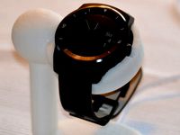
Mio Alpha Stand by menzenbach
...ercad.
it covers the original charging module.
slightly improved version v2 covers now the full height of the charging mount.
thingiverse
free
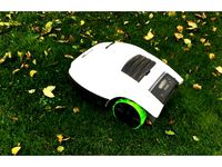
Robomow RM510 wheel by menzenbach
...screwed together. the tyre profile is printed with tpu. this gives significant more grip and reduces the noise on solid surfaces.
thingiverse
free

Braun Oral B toothbrush holder by menzenbach
...p://www.thingiverse.com/thing:38046/#files. removed the upper fixing for easier handling and added a intake for a cupping vessel.
thingiverse
free
G Watch R Charging Dock by menzenbach
... that the charging cradle is squeezed in the stand!
note: this design requires glue.dis-assembly might destroy the printed parts!
thingiverse
free

G Watch R Charging Dock - Version 2 by menzenbach
...sb cable can be easily removed.
there is a long and short variant available. the short one works well with the stock usb cable.
thingiverse
free
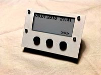
E-Ink Display Console by menzenbach
...he display this should be shipped together with the display.
screws and nuts.
see also: https://www.thingiverse.com/thing:2789144
thingiverse
free

4.2" E-Ink Display Console by menzenbach
...ph connector.
4 thumbtacks
dupont jumper wire - optionally if you don't want to solder the buttons directly.
screws and nuts.
thingiverse
free

Huawei Watch Charging Stand by agentdr8
...watch. inspired by the g watch r dock by menzenbach but adapted to fit the fixed usb connector on...
thingiverse
free
2.7 e-ink display (waveshare) 264*176 by Movil
...esp32 screen manager this is a bigger version of https://www.thingiverse.com/menzenbach e-ink display. i liked his design very much and...
Darrieus
thingiverse
free
rotor darrieus by david55384
...rotor darrieus by david55384
thingiverse
it's a normal rotor darrieus
thingiverse
free

Darrieus type windmill by Kavetj
...darrieus type windmill by kavetj
thingiverse
a windmill i drawed. i used pictures of darrieus type to make this one.
thingiverse
free
Savonius Darrieus Turbine by astfaellergerald
...leber für die flügel
ca 250g abs und 12 std. druckzeit
die turbine verbindet die vorteile der savonius- und der darrieus- turbine
thingiverse
free
Darrieus Windturbine by sroddier
...atch?v=pd-qcghlfkg
https://www.youtube.com/watch?v=z_9fblycpwe
modele réduit d'une de nos éoliennes pour le concours gimeole.
thingiverse
free

MakerBot-able/RepRap-able Darrieus Turbine by cyrozap
...all i really did was lop off one end. i haven't sent it through meshlab yet so there are a few errors, but it should be fine.
thingiverse
free
Parametric helical Darrieus vertical axis wind turbine - Mk2 by qharley
...der to couple the turbine to a m8 threaded rod. the rod serves as a bearing carrier and drive shaft to the generator.
added stls
thingiverse
free
Parametric helical Darrieus vertical axis wind turbine by qharley
...s again to buzz for his parametric naca airfoil code.
this project is dependent on the parametric naca4 library i posted earlier.
thingiverse
free
Darrieus VAWT - Wendel/S by swb
...it/lr/organisatie/afdelingen_en_leerstoelen/afdeling_aewe/aerodynamics/contributor_area/secretary/m._sc._theses/doc/2006_1_17.pdf
thingiverse
free
Vertical-Axis Wind Turbine (medium scale) by haydnv
...haydnv thingiverse this is a rough draft of a darrieussavonius combination vertical-axis wind turbine intended for use with an...
Helix
design_connected
$9
Helix
...helix
designconnected
brent comber helix computer generated 3d model. designed by comber, brent.
turbosquid
free

Helix
...helix
turbosquid
free 3d model helix for download as fbx on turbosquid: 3d models for games, architecture, videos. (1490983)
3d_ocean
$20

Helix SPXL12
...helix spxl12
3docean
all and helix included of rendered scene setups spxl12 subwoofer the vray with
subwoofer helix spxl12
turbosquid
$69

Helix
... available on turbo squid, the world's leading provider of digital 3d models for visualization, films, television, and games.
3d_export
$5

Helix 3D Model
...helix 3d model
3dexport
helix
helix 3d model jopaas 82470 3dexport
turbosquid
$62

helix bridge
...squid
royalty free 3d model helix bridge for download as skp on turbosquid: 3d models for games, architecture, videos. (1345787)
turbosquid
$10
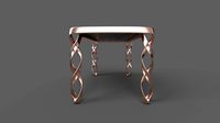
Helix Table
...osquid
royalty free 3d model helix table for download as obj on turbosquid: 3d models for games, architecture, videos. (1174648)
turbosquid
$5

Helix Lamp
...ty free 3d model helix lamp for download as c4d, obj, and fbx on turbosquid: 3d models for games, architecture, videos. (1631703)
turbosquid
$333

Townscape: HELIX
... available on turbo squid, the world's leading provider of digital 3d models for visualization, films, television, and games.
turbosquid
$200

DNA Helix
... available on turbo squid, the world's leading provider of digital 3d models for visualization, films, television, and games.
Hybrid
3d_export
$10
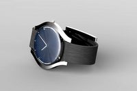
hybrid watch
...hybrid watch
3dexport
turbosquid
$5

Hybrid Scope
...ree 3d model hybrid scope for download as blend, fbx, and obj on turbosquid: 3d models for games, architecture, videos. (1533651)
turbosquid
$39
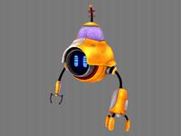
Robot Hybrid
... 3d model robot hybrid for download as max, obj, fbx, and dae on turbosquid: 3d models for games, architecture, videos. (1373779)
turbosquid
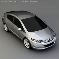
$199

Hybrid Car
... available on turbo squid, the world's leading provider of digital 3d models for visualization, films, television, and games.
archive3d
free

Hybrid 3D Model
...id 3d model
archive3d
aircraft
hybrid 6 - 3d model (*.gsm+*.3ds) for interior 3d visualization.
3d_export
$25
Honda insight hybrid 3D Model
...t hybrid 3d model
3dexport
honda insight-hybrid car vehicle insight hybrid
honda insight hybrid 3d model artline3d 26442 3dexport
3d_export
$45

Hybrid ce456 3D Model
...hybrid ce456 3d model
3dexport
alien robot 3d hybrid terminator code red flying camera
hybrid ce456 3d model dan3d 84278 3dexport
3ddd
$1

Hybrid Task Floor Light
...ight up your room in style with this contemporary hybrid task floor lamp, a great accessory for adding a fresh touch to the home.
turbosquid
$6
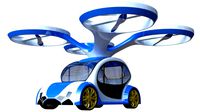
Hybrid drone car
...
royalty free 3d model hybrid drone car for download as blend on turbosquid: 3d models for games, architecture, videos. (1602619)
turbosquid
$5

AK12 with hybrid sight
...alty free 3d model ak12 with hybrid sight for download as skp on turbosquid: 3d models for games, architecture, videos. (1261141)
Rotor
design_connected
$4
Rotor
...rotor
designconnected
bellato international rotor coffee tables computer generated 3d model. designed by luciano bertoncini.
3ddd
free
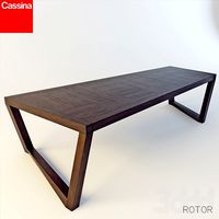
Cassina / Rotor
...assina / rotor
3ddd
cassina , обеденный
стол cassina/rotor
габаритные размеры 303x123x74
turbosquid
$5
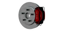
Brake Rotor
...3d model brake rotor for download as obj, fbx, blend, and dae on turbosquid: 3d models for games, architecture, videos. (1288076)
turbosquid
$3
Brake rotor
...e 3d model brake rotor for download as 3ds, max, obj, and fbx on turbosquid: 3d models for games, architecture, videos. (1318483)
turbosquid
$30

rotor disk
... available on turbo squid, the world's leading provider of digital 3d models for visualization, films, television, and games.
turbosquid
$29

Rotor Slide
... available on turbo squid, the world's leading provider of digital 3d models for visualization, films, television, and games.
turbosquid
$8
Brake Rotor
... available on turbo squid, the world's leading provider of digital 3d models for visualization, films, television, and games.
turbosquid
$1

Brake Rotor
... available on turbo squid, the world's leading provider of digital 3d models for visualization, films, television, and games.
turbosquid
free
Brakr Rotor
... available on turbo squid, the world's leading provider of digital 3d models for visualization, films, television, and games.
turbosquid
$35

helicopter rotor system
...oyalty free 3d model helicopter rotor system for download as on turbosquid: 3d models for games, architecture, videos. (1598497)