Thingiverse
HUGE DNA Lamp REMIX by relic
by Thingiverse
Last crawled date: 3 years ago
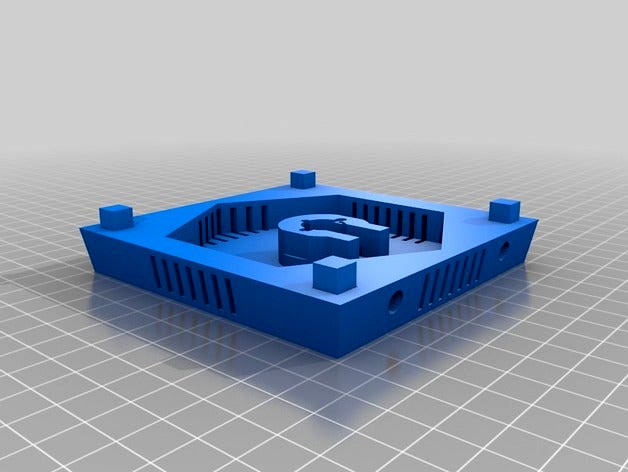
This is a REMIX of the award-winning DNA Lamp created by "joaoduarte". I wanted to super-size his design. Most of his original parts were printed @ 200% scale on a CR-10 printer. I used a different motor and support design. His original design used an acrylic cylinder and a motor from a microwave oven. I used a small stepper motor, UV LED's, 7805 regulator, 9V wall wart (1 amp), 2 NPN transistors and an arduino micro.
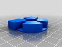
I redesigned the lamp base and created a simple support structure. The motor model is provided simply to test-fit into the printed base.
Schematic and Arduino code below ...
Code:
include
define HALFSTEP 8
define motorPin1 3 // IN1 on the ULN2003 driver 1
define motorPin2 4 // IN2 on the ULN2003 driver 1
define motorPin3 5 // IN3 on the ULN2003 driver 1
define motorPin4 6 // IN4 on the ULN2003 driver 1
define ledPin1 9 // Bottom LED Array
define ledPin2 10 // Top LED Array
AccelStepper stepper1(HALFSTEP, motorPin1, motorPin3, motorPin2, motorPin4);
unsigned long int timer = 0;
unsigned short int pwmValue = 0;
boolean pwmIncrement = true;
unsigned short int delayTime = 50;
unsigned int motorSpeed = 200;
void setup()
{
pinMode(ledPin1, OUTPUT);
pinMode(ledPin2, OUTPUT);
stepper1.setMaxSpeed(1000.0);
stepper1.setAcceleration(100.0);
stepper1.setSpeed(motorSpeed);
stepper1.moveTo(30000);
timer = millis() + delayTime;
Serial.begin(9600);
printSerial();
}
void loop()
{
//Change direction when the stepper reaches the target position
if (stepper1.distanceToGo() == 0)
{
stepper1.moveTo(-stepper1.currentPosition());
printSerial();
}
stepper1.run();
// check timer to change PWM LED values
unsigned long currentTime = millis();
if(currentTime > timer)
{
if(pwmIncrement == true)
{
pwmValue ++;
if(pwmValue == 255) // max pwm increment value
{ // if = to or above then swith direction
pwmIncrement = false; // time to decrement if = to 255
randomSeed(analogRead(0)); // at end of each sequence randomize pwm and motor speed
delayTime = random(10, 200);
motorSpeed = random(100, 1000);
}
}
if(pwmIncrement == false)
{
pwmValue --;
if(pwmValue == 0) // min pwm value
{
pwmIncrement = true; // time to increment again if = to or less than 50
randomSeed(analogRead(0)); // at end of each sequence randomize pwm and motor speed
delayTime = random(10, 200);
motorSpeed = random(100, 1000);
}
}
analogWrite(ledPin1, pwmValue); // now set LED pwm values
analogWrite(ledPin2, pwmValue);
timer = millis() + delayTime; // reset the timer !!!
}
}
void printSerial()
{
Serial.print("PWM DELAY = ");
Serial.print(delayTime);
Serial.print("\tMOTOR SPEED = ");
Serial.println(motorSpeed);
}
Schematic will follow at some point. I'll provide some basic instructions below that most people with arduino and electronics experience will be able to follow.
On a prototyping board I have a 7805 regulator for the 5 volt rail. The motor can run on 5V or 9-12 volts on the power supply. Use 1k resistors between the arduino PWM pinouts and the base of the NPN transistors. These power the 16 or so UV LED's. The PWM and motor speed are random in duration in code. General purpose NPN's can be used, however I opted for a Texas Instruments chip with 7 darlington pair inputs/outputs. It is basically 7 transistors on a chip.
Connect the stepper motor driver board to the pins listed in the arduino code. I'm running mine on the 5 volt rail. I used enameled coil wire up the support piece to power the top UV LED's. By pre-twisting the wires together, they are hardly noticable.
Hot glue was used to attach just about everything. The support structure's 3 legs may need to be trimmed evenly
There are 2 holes on the lamp base: One for a 2.5mm power input (the panel mount type) and the other for a panel mount switch. Most of these components can be found at Tayda Electronics' website.
Similar models
thingiverse
free
The 3D Printed Marble Machine 3 stepper mod 28byj-48 by melb
...n4);
void setup()
{
stepper1.setmaxspeed(2000);
stepper1.setspeed(-1100);
}
void loop()
{
stepper1.runspeed();
}
thingiverse
free

SLA DLP UV cure box by coldakin
...reaches the target position
if (stepper1.distancetogo() == 0) {
stepper1.moveto(-stepper1.currentposition());
}
stepper1.run();
}
thingiverse
free

ARMDUINO V1 Open-Source Robotic Arm! by Doctorfizzle
...urnval);
analogwrite(led1, turnval / 8 - 120);
analogwrite(led2, firstval / 8 - 120);
analogwrite(led3, secondval / 8 - 120);
}
thingiverse
free

Lighthouse - Isle of Lewis - Scale Model by CPomeroy
... = 450 ; x >= 0; x--) {
int brightness = 1+(x/7.63);
analogwrite(0, brightness);
delay(1);
}
analogwrite(0, 1);
delay(3800);
}
thingiverse
free

Chromotherapy Christmas House by STEMaker
...e(9, low);
digitalwrite(10, low);
digitalwrite(11, low);
}
// slight delay so it doesn't rotate color too quicky
delay(33);
}
thingiverse
free
Automatic fish feeding device by pepperl
...step(3500); //how much
}
if(currentmillis < previousmillis){ //overflow check
previousmillis=currentmillis;
}
}
thingiverse
free

Tali's Mask - LED Sound Reactive by Pandariot779
...rgb values. in this case r=150, g=150, b=150
int bvalue = map(value, 0, 30, 0, 255);
pixel.setbrightness(bvalue);
pixel.show();
}
grabcad
free

case for Digispark Attiny85
...ecommendation:
petg filament
layer height 0.2 mm
nozzle 0.6 or 0.4 mm
15% - 20% filling
without supports
orient the x on the bed
thingiverse
free

Motion sensing night light by SteveOst
...talwrite(led1,low);
digitalwrite(led2,low);
}
serial.println("motion");
serial.print(motionvalue);
}
else
{
delay(300);
grabcad
free

Harry Vader's fully armed and operational Elder Light Saber Wand
...nalogwrite(blueled, 255);
}
else{
analogwrite(blueled, 0);
}
delay(5);
}
// end mode 5
}
// end main loop
Relic
turbosquid
$2

Relic
... available on turbo squid, the world's leading provider of digital 3d models for visualization, films, television, and games.
turbosquid
$1

Relic
...ree 3d model relic for download as ma, obj, fbx, flt, and dae on turbosquid: 3d models for games, architecture, videos. (1379990)
3d_export
$18

antique-cultural relics-art-ceramics 01
...antique-cultural relics-art-ceramics 01
3dexport
antique-cultural relics-art-ceramics 01<br>3ds max 2015
3d_export
$18

antique-cultural relics-art-terracotta 14
...antique-cultural relics-art-terracotta 14
3dexport
antique-cultural relics-art-terracotta 14<br>3ds max 2015
3d_export
$19
3D Ceramic Horse Sculpture ancient cultural relics
...amic horse sculpture ancient cultural relics
3dexport
1.3d ceramic horse sculpture ancient cultural relics 2.files include 3dmax
3d_export
$18

antique-cultural relics-art-ceramic workshop 12
...antique-cultural relics-art-ceramic workshop 12
3dexport
antique-cultural relics-art-ceramic workshop 12<br>3ds max 2015
turbosquid
$12

Statues stone carvings bronze horse relics
...es stone carvings bronze horse relics for download as max on turbosquid: 3d models for games, architecture, videos. (1636938)
turbosquid
$12

Ceramic Horse Sculpture ancient cultural relics
...orse sculpture ancient cultural relics for download as max on turbosquid: 3d models for games, architecture, videos. (1629677)
turbosquid
$12

Cultural Relics unearthed ancient tripod container bronze
...earthed ancient tripod container bronze for download as max on turbosquid: 3d models for games, architecture, videos. (1636952)
turbosquid
$12

Ancient artifacts unearthed cultural relics bronze tripod
... unearthed cultural relics bronze tripod for download as max on turbosquid: 3d models for games, architecture, videos. (1614417)
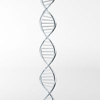
Dna
3d_export
$19

DNA
...dna
3dexport
3d model of the dna textures 8k
design_connected
$9
DNA
...dna
designconnected
next home collection dna computer generated 3d model. designed by hopf, benjamin.
3d_export
$5

DNA
...dna
3dexport
3d_ocean
$1
DNA Strand
...dna strand
3docean
d.n.a dna strand
accurate 3d model of a dna strand
turbosquid
free

DNA
...dna
turbosquid
free 3d model dna for download as max on turbosquid: 3d models for games, architecture, videos. (1497359)
turbosquid
$9

DNA
...a
turbosquid
royalty free 3d model dna for download as blend on turbosquid: 3d models for games, architecture, videos. (1667313)
turbosquid
$1

Dna
...dna
turbosquid
royalty free 3d model dna for download as fbx on turbosquid: 3d models for games, architecture, videos. (1410365)
3ddd
$1
Next / DNA
...next / dna
3ddd
next , dna
http://www.next.de/cms/en/dna-en
turbosquid
$45

DNA
...
royalty free 3d model dna for download as max, fbx, and obj on turbosquid: 3d models for games, architecture, videos. (1622745)
turbosquid
free

DNA
...
free 3d model dna for download as ma, c4d, lwo, max, and obj on turbosquid: 3d models for games, architecture, videos. (1521540)
Huge
turbosquid
$4

Huge Fungus
...royalty free 3d model huge fungus for download as 3ds and max on turbosquid: 3d models for games, architecture, videos. (1310036)
3d_export
$5

Huge Treee 3D Model
...huge treee 3d model
3dexport
huge tree
huge treee 3d model nikkistinger19 38424 3dexport
turbosquid
$3

Sofa huge grey
...osquid
royalty free 3d model sofa huge grey for download as on turbosquid: 3d models for games, architecture, videos. (1526303)
turbosquid
$149

Huge City 03
... available on turbo squid, the world's leading provider of digital 3d models for visualization, films, television, and games.
turbosquid
$70

Stillux GliOri Huge
... available on turbo squid, the world's leading provider of digital 3d models for visualization, films, television, and games.
3ddd
$1
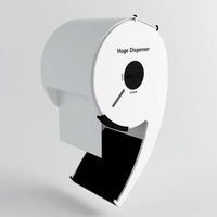
Huge Dispenser
...huge dispenser
3ddd
диспенсер
designer: mr. jin-seok kwon
design type: public space design
launch year: 2013
turbosquid
$549

HUGE CUTE ROBOT II
...3d model huge cute robot ii for download as max, obj, and fbx on turbosquid: 3d models for games, architecture, videos. (1500470)
3ddd
$1

Stillux GliOri Huge Art. 7801 8
... huge
люстра итальянской фабрики stillux, коллекция gliori, серия huge арт. 7801
размеры: d78 h70
3ddd
$1

Stillux GliOri Huge Art. 8800 6
... huge
люстра итальянской фабрики stillux, коллекция gliori, серия huge арт.8800
размеры: d70 h60
turbosquid
$550

Huge Bridge Collection 1
... available on turbo squid, the world's leading provider of digital 3d models for visualization, films, television, and games.
Remix
turbosquid
$5
MODA Collection Remix Chair
... available on turbo squid, the world's leading provider of digital 3d models for visualization, films, television, and games.
3d_export
$12
remix yamaha rm1x
...remix yamaha rm1x
3dexport
geometry triangles 15.2k vertices 7.6k pbr no textures 1 materials 1 uv layers yes
3d_ocean
$5
Vray fabric Kvadrat remix green - tileable
...th vray and 3dsmax. high-resolution texture images (2000×2000 px) file included: shader vray 2.40 texture image 3ds max 2011 file
turbosquid
$20

Gerrit Rietveld 1938 Zig Zag Chair Remix
... available on turbo squid, the world's leading provider of digital 3d models for visualization, films, television, and games.
3d_export
$10

multicolored remix parametric table furniture
... fbx, obj, mtl, archive with textures. the model has no glitches. render and materials - vray . without using plugins. good use!
3ddd
$1
Barovier&Toso / Manhattan Remix 7192
... 004293-142405
в коллекции есть люстры 7, 9, 12 рожковые. диаметр соответственный 1000, 1250, 1500 мм.
3ddd
$1

Muuto fiber chair
...grey/grey, dusty green/dusty green, nature/oak, natural white/oak upholstery options remix 183/black, remix 133/grey, remix 643/dusty red leather options black...
3ddd
$1
Barovier&Toso 7190-7195
...7190-7195 3ddd barovier&toso потолочнай люстра фабрики barovier&toso;, коллекция manhattan remix артикул 7190-7195. размеры в inches: 39"...
3d_export
$5
3D Locking Handle Weatherproof Storage Box Container
...handle weatherproof storage box container 3dexport new, improved and remixd! no screws required. print-in-place. weatherproof. parametric. 2 parts. easy...
cg_studio
$49

HTC One Mini 2 Amber Gold3d model
...cell phone mobile cellular super lcd touchscreen touch screen remix amber gold .max .obj .mb .lwo .fbx .c4d .3ds...
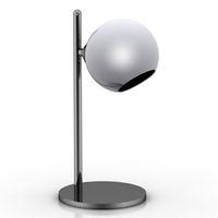
Lamp
archibase_planet
free
Lamp
...lamp
archibase planet
lamp reading lamp table lamp
lamp - 3d model (*.gsm+*.3ds) for interior 3d visualization.
archibase_planet
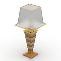
free
Lamp
...lamp
archibase planet
lamp reading lamp table lamp
lamp - 3d model (*.gsm+*.3ds) for interior 3d visualization.
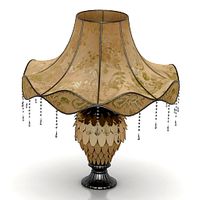
archibase_planet
free

Lamp
...lamp
archibase planet
lamp table lamp reading lamp
lamp - 3d model (*.gsm+*.3ds) for interior 3d visualization.
archibase_planet
free

Lamp
...lamp
archibase planet
lamp table lamp reading lamp
lamp - 3d model (*.gsm+*.3ds) for interior 3d visualization.
archibase_planet
free
Lamp
...lamp
archibase planet
lamp reading lamp table lamp
lamp - 3d model (*.gsm+*.3ds) for interior 3d visualization.
archibase_planet
free

Lamp
...lamp
archibase planet
lamp reading lamp table lamp
lamp - 3d model (*.gsm+*.3ds) for interior 3d visualization.
archibase_planet
free
Lamp
...lamp
archibase planet
lamp table lamp reading lamp
lamp - 3d model (*.gsm+*.3ds) for interior 3d visualization.
archibase_planet
free

Lamp
...lamp
archibase planet
lamp table lamp reading lamp
lamp - 3d model (*.gsm+*.3ds) for interior 3d visualization.
archibase_planet
free
Lamp
...lamp
archibase planet
lamp reading lamp table lamp lantern
lamp - 3d model (*.3ds) for interior 3d visualization.
3d_ocean
$6

Lamp
...lamp
3docean
lamp
a high quality lamp.