Thingiverse
How To Wire a RAMPS 1.x by morganlowe
by Thingiverse
Last crawled date: 3 years ago
So this one is all about wiring the RAMPS board. My other one about how to put Marlin on RAMPS and an Anet A8 is here: https://www.thingiverse.com/thing:2783450 Be sure to check it out!
If you download this thing it includes the carriage from https://www.thingiverse.com/thing:2766701
See the Octoprint and GPIO tutorial here!
See the Marlin Firmware tutorial here!
So first thing first this is as universal as a guide as I can do. It's packed with information I gathered working on my Anet A8. It was made with a $12 RAMPS 1.4 from Amazon.com and some equally as cheap DRV8825 stepper boards.
I really recommend you use the RAMPS 1.6 now!
This is a pretty universal and recommended setup and I hope this guide helps you out!
NEVER work on electrical appliances with mains power attached.
Unplug, isolate and be sure that everything is safe before you begin.
On to it!
First step is to mount the RAMPS board to your Arduino.
This is the Arduino MEGA 2560 board. To mount your RAMPS to it just align the pins and gently push them together.
Now let's take a look at the RAMPS 1.4
Here in this poorly lit up-side-down picture is the colorful board I choose for my $12. It's cheap, made in China but it works. I'm not really saying you need this exact one or anything so feel free to choose any RAMPS 1.4,1.5 or 1.6 you wish. The difference is the 1.5 and 1.6 board has the MOSFETS surface mounted. This is better in my opinion because they get better heat dissipation and just aren't flappin' in the breeze as Dave Jones says.
Install stepper drivers
So let's install our stepper boards first. This guide is meant for the DRV8825 as seen here:
Here's my used, dirty DRV8825 boards. 5 of them since I have dual extruders. Take careful note of the direction they install. This is opposite the cheaper A4988 boards. Also these boards are higher resolution and require different jumper or firmware settings.
So the 1/16th step is the default setting in most cases and the maximum a A4988 can do. The 1/32 step is the maximum the DRV8825 can do and is more precise with slightly less torque. Not normally a worry in 3d printing.
This setting corresponds with the setting '#define DEFAULT_AXIS_STEPS_PER_UNIT {200, 200, 800, 200}' in your firmware. That example is for 1/32 steps on an Anet A8.
So with that covered and setup you can install the boards!
Be careful about the direction! Reversing the board can cause damage!
Notice the adjustment pots are to the left side in the photo, towards the input connector of the RAMPS board. This is opposite the A4988 boards.
Now it's time to connect some wires.
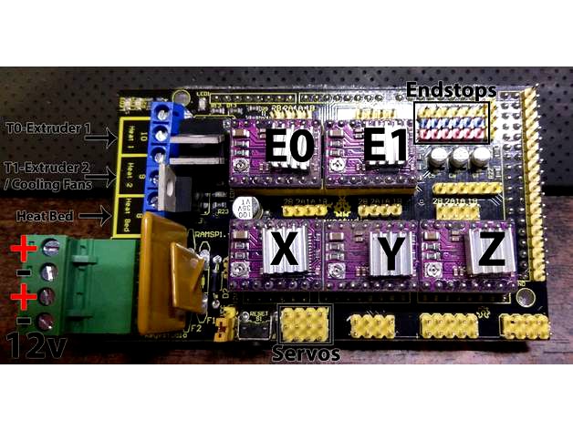
Have a look at this photo and lets start at the main power connector lower left. The upper part is the 11amp circuit for the heated bed and the lower part is the 6amp circuit for the hotends. I always use external MOSFETS and in most cases you can hook these together at the power supply. These are 12 volt connections.
The connections are from top to bottom:
Positive12v 11amp
Ground
Positive 12v 6amp
Ground
Extruder and bed connections
Above that connector is a set of 6 screw terminals for the hotends, fans and heat bed. These are not labeled negative and positive but generally the one closest to the power connector is positive. The heaters don't care about polarity but if you use the part cooling fan attachments you may need to check polarity.
These connections are from top to bottom:
T0 / Extruder 1
T1 / Extruder 2 or Part Cooling Fans for single extruder [never both! See below for more info on cooling fans with dual extruders]
Heated Bed
The top one is for T0 / extruder 1. This is your primary heater in the extruder or the MOSFET for it.
Next is the T1 / Extruder 2 connection. This is used for the part cooling fans in a single extruder setup or extruder 2 in a dual extruder setup. Never attach both fans and an extruder here. See below for more information.
Closest to the power connector you have the heated bed connection. Run this to your MOSFET for bed heat or to the bed if it is small and low wattage.
Above this connector is a few status LEDs.
Moving on to the steppers you see the axis marked on the stepper board. at the top right corner of each stepper driver on the RAMPS board is a 4 pin header. There is 2 for the Z axis. This is there you attach the stepper wires. They are not marked for direction so if you find axis backwards you can flip the connection or correct it in firmware.
Bottom center is the servo connections. These are not used commonly though if you have dual extruders the right most servo connection if for driving a MOSFET to run your cooling fans. They are also used for BLTouch connections.
Endstops
Top right you have the connections for endstops. From bottom to top you have +5 volts, - ground and signal. Most setups expect the signal to be pulled down, or to have it shorted to - negative. This is again configurable in firmware.
For the endstops from left to right they are
X min
X max
Y min
Y max
Z min
Z max
Here's an endstop switch attached. Notice the position of the wires. From left to right they are Signal, Ground and Positive 5v.
For reference this is the endstop switch I use. It's a common one from Ebay or Amazon, I forgot.
Thermal Sensors
For our temperature sensors the connections attach to the pins after the Extruder 1 stepper controller. These do not have a polarity!
Cooling fan for dual extruders!
Now back to that Fan and MOSFET thing for dual extruders. The servo pins far right of the picture above are from top to bottom:
D4
Positive 5v
Ground
For the MOSFET I like to use these cheap little 5amp Arduino compatible ones like below.
Besides being cheap they are ready to connect to an Arduino and have nice screw connections for the 12volt required by the fans. You hook them up as follows on the servo connector:
SIG to D4
VCC to Positive 5v
GND to Ground
On the screw terminals it's:
V+ to Fan Positive
V- to Fan Ground
VIN to +12v
GND to Ground
You cannot common the ground across these terminals.
When '#define MOTHERBOARD BOARD_RAMPS_14_EEB ' is selected in Marlin it will automatically switch the PWM signal for the fans to the Servo / D4 pins.
LCD
Last we have the LCD and SD card connections. These commonly use whats called a Smart Adapter to connect to the RAMPS board. The adapter uses the long pin header along the right edge and the aux port below to connect to a pair of 10 conductor cables for ease of use.
Here you can see the Smart Adapter in white with the two 10 pin cables attached. These cables run up to your LCD.
There's my RepRap Discount LCD in a printed enclosure on my Anet A8.
And there's the back of it with the cables.
Setting motor drive current
This needs to be done with power applied to the RAMPS board.
While this is typically only 12 volts you can cause damage by shorting things out.
Be careful what you stick where!
The little thing in the circle is how you adjust the drive current. This is important to not burn up drives or motors, or just skip steps due to low power.
To find motor current use this formula: Current in Amps = VREF × 2
VREF can be found be measuring between the point marked in the red circle and GND of the 12v power input.
Here you can see my VREF at 0.66 volts. This gives a current of 1.32amps at the motor. Since I have 1.5amp motors this works really well.
The easy way to set this is to connect the GND of your meter to the GND of your power supply somewhere close to the RAMPS board.
Then hold or clip your positive meter lead to the shaft of a small Philips screwdriver that fits the pot as shown below.
I'm just using my fingers to hold the probe to the shaft to read the voltage as the pot is turned.
And that's it, the current is now set!
To flash your firmware see https://www.thingiverse.com/thing:2783450
For more information and the links I got my info from see below:
https://www.thingiverse.com/thing:2783450
http://3d-maker.info/switching-to-ramps-1-4-wiring-anettronxy/
http://reprap.org/mediawiki/images/6/6d/Rampswire14.svg
http://reprap.org/mediawiki/images/3/3f/Arduinomegapololushieldschematic.png
http://www.reprap.org/mediawiki/images/0/06/RAMPS_dossier.pdf
https://makershopbcn.com/en/product/drv8825-stepper-driver-pololu-2
http://reprap.org/wiki/A4988_vs_DRV8825_Chinese_Stepper_Driver_Boards
http://www.instructables.com/id/Installing-and-Configuring-DRV8825-Stepper-Drivers/
http://www.geeetech.com/wiki/index.php/Ramps1.4
http://reprap.org/wiki/RepRapDiscount_Full_Graphic_Smart_Controller
https://www.pololu.com/product/2133
I think that pretty much wraps this up. I hope this helps, enjoy, like and share with your friends!
Thank you Thingiverse community!
If you download this thing it includes the carriage from https://www.thingiverse.com/thing:2766701
See the Octoprint and GPIO tutorial here!
See the Marlin Firmware tutorial here!
So first thing first this is as universal as a guide as I can do. It's packed with information I gathered working on my Anet A8. It was made with a $12 RAMPS 1.4 from Amazon.com and some equally as cheap DRV8825 stepper boards.
I really recommend you use the RAMPS 1.6 now!
This is a pretty universal and recommended setup and I hope this guide helps you out!
NEVER work on electrical appliances with mains power attached.
Unplug, isolate and be sure that everything is safe before you begin.
On to it!
First step is to mount the RAMPS board to your Arduino.
This is the Arduino MEGA 2560 board. To mount your RAMPS to it just align the pins and gently push them together.
Now let's take a look at the RAMPS 1.4
Here in this poorly lit up-side-down picture is the colorful board I choose for my $12. It's cheap, made in China but it works. I'm not really saying you need this exact one or anything so feel free to choose any RAMPS 1.4,1.5 or 1.6 you wish. The difference is the 1.5 and 1.6 board has the MOSFETS surface mounted. This is better in my opinion because they get better heat dissipation and just aren't flappin' in the breeze as Dave Jones says.
Install stepper drivers
So let's install our stepper boards first. This guide is meant for the DRV8825 as seen here:
Here's my used, dirty DRV8825 boards. 5 of them since I have dual extruders. Take careful note of the direction they install. This is opposite the cheaper A4988 boards. Also these boards are higher resolution and require different jumper or firmware settings.
So the 1/16th step is the default setting in most cases and the maximum a A4988 can do. The 1/32 step is the maximum the DRV8825 can do and is more precise with slightly less torque. Not normally a worry in 3d printing.
This setting corresponds with the setting '#define DEFAULT_AXIS_STEPS_PER_UNIT {200, 200, 800, 200}' in your firmware. That example is for 1/32 steps on an Anet A8.
So with that covered and setup you can install the boards!
Be careful about the direction! Reversing the board can cause damage!
Notice the adjustment pots are to the left side in the photo, towards the input connector of the RAMPS board. This is opposite the A4988 boards.
Now it's time to connect some wires.
Have a look at this photo and lets start at the main power connector lower left. The upper part is the 11amp circuit for the heated bed and the lower part is the 6amp circuit for the hotends. I always use external MOSFETS and in most cases you can hook these together at the power supply. These are 12 volt connections.
The connections are from top to bottom:
Positive12v 11amp
Ground
Positive 12v 6amp
Ground
Extruder and bed connections
Above that connector is a set of 6 screw terminals for the hotends, fans and heat bed. These are not labeled negative and positive but generally the one closest to the power connector is positive. The heaters don't care about polarity but if you use the part cooling fan attachments you may need to check polarity.
These connections are from top to bottom:
T0 / Extruder 1
T1 / Extruder 2 or Part Cooling Fans for single extruder [never both! See below for more info on cooling fans with dual extruders]
Heated Bed
The top one is for T0 / extruder 1. This is your primary heater in the extruder or the MOSFET for it.
Next is the T1 / Extruder 2 connection. This is used for the part cooling fans in a single extruder setup or extruder 2 in a dual extruder setup. Never attach both fans and an extruder here. See below for more information.
Closest to the power connector you have the heated bed connection. Run this to your MOSFET for bed heat or to the bed if it is small and low wattage.
Above this connector is a few status LEDs.
Moving on to the steppers you see the axis marked on the stepper board. at the top right corner of each stepper driver on the RAMPS board is a 4 pin header. There is 2 for the Z axis. This is there you attach the stepper wires. They are not marked for direction so if you find axis backwards you can flip the connection or correct it in firmware.
Bottom center is the servo connections. These are not used commonly though if you have dual extruders the right most servo connection if for driving a MOSFET to run your cooling fans. They are also used for BLTouch connections.
Endstops
Top right you have the connections for endstops. From bottom to top you have +5 volts, - ground and signal. Most setups expect the signal to be pulled down, or to have it shorted to - negative. This is again configurable in firmware.
For the endstops from left to right they are
X min
X max
Y min
Y max
Z min
Z max
Here's an endstop switch attached. Notice the position of the wires. From left to right they are Signal, Ground and Positive 5v.
For reference this is the endstop switch I use. It's a common one from Ebay or Amazon, I forgot.
Thermal Sensors
For our temperature sensors the connections attach to the pins after the Extruder 1 stepper controller. These do not have a polarity!
Cooling fan for dual extruders!
Now back to that Fan and MOSFET thing for dual extruders. The servo pins far right of the picture above are from top to bottom:
D4
Positive 5v
Ground
For the MOSFET I like to use these cheap little 5amp Arduino compatible ones like below.
Besides being cheap they are ready to connect to an Arduino and have nice screw connections for the 12volt required by the fans. You hook them up as follows on the servo connector:
SIG to D4
VCC to Positive 5v
GND to Ground
On the screw terminals it's:
V+ to Fan Positive
V- to Fan Ground
VIN to +12v
GND to Ground
You cannot common the ground across these terminals.
When '#define MOTHERBOARD BOARD_RAMPS_14_EEB ' is selected in Marlin it will automatically switch the PWM signal for the fans to the Servo / D4 pins.
LCD
Last we have the LCD and SD card connections. These commonly use whats called a Smart Adapter to connect to the RAMPS board. The adapter uses the long pin header along the right edge and the aux port below to connect to a pair of 10 conductor cables for ease of use.
Here you can see the Smart Adapter in white with the two 10 pin cables attached. These cables run up to your LCD.
There's my RepRap Discount LCD in a printed enclosure on my Anet A8.
And there's the back of it with the cables.
Setting motor drive current
This needs to be done with power applied to the RAMPS board.
While this is typically only 12 volts you can cause damage by shorting things out.
Be careful what you stick where!
The little thing in the circle is how you adjust the drive current. This is important to not burn up drives or motors, or just skip steps due to low power.
To find motor current use this formula: Current in Amps = VREF × 2
VREF can be found be measuring between the point marked in the red circle and GND of the 12v power input.
Here you can see my VREF at 0.66 volts. This gives a current of 1.32amps at the motor. Since I have 1.5amp motors this works really well.
The easy way to set this is to connect the GND of your meter to the GND of your power supply somewhere close to the RAMPS board.
Then hold or clip your positive meter lead to the shaft of a small Philips screwdriver that fits the pot as shown below.
I'm just using my fingers to hold the probe to the shaft to read the voltage as the pot is turned.
And that's it, the current is now set!
To flash your firmware see https://www.thingiverse.com/thing:2783450
For more information and the links I got my info from see below:
https://www.thingiverse.com/thing:2783450
http://3d-maker.info/switching-to-ramps-1-4-wiring-anettronxy/
http://reprap.org/mediawiki/images/6/6d/Rampswire14.svg
http://reprap.org/mediawiki/images/3/3f/Arduinomegapololushieldschematic.png
http://www.reprap.org/mediawiki/images/0/06/RAMPS_dossier.pdf
https://makershopbcn.com/en/product/drv8825-stepper-driver-pololu-2
http://reprap.org/wiki/A4988_vs_DRV8825_Chinese_Stepper_Driver_Boards
http://www.instructables.com/id/Installing-and-Configuring-DRV8825-Stepper-Drivers/
http://www.geeetech.com/wiki/index.php/Ramps1.4
http://reprap.org/wiki/RepRapDiscount_Full_Graphic_Smart_Controller
https://www.pololu.com/product/2133
I think that pretty much wraps this up. I hope this helps, enjoy, like and share with your friends!
Thank you Thingiverse community!
Similar models
thingiverse
free

RAMPS Fan Holder by BensHacks
...thingiverse.com/thing:2169986 but might also fit with other assembly's.
=> this part is used in my prusa i3 master rework
thingiverse
free

40mm Fan Duct for RAMPS 1.4 with DRV8825 by alvarohenriques
...mall change to be used with drv8825 stepper motor driver's, from original creation @ http://www.thingiverse.com/thing:730034.
thingiverse
free

12V Aux Power Rail for RAMPS and 2020 Extrusion by gregington
...ale to female dupont connectors.
connect your 12v accessories to the remaining header pins. ensure you have the polarity correct.
thingiverse
free
Ender 3 Max BLTouch Bracket and Marlin 2.0.7.2 firmware by riazshaikgp
...e you flash your board with the correct firmware. the bondtech extruder stepper unit size is 415 vs 93 for the standard extruder.
grabcad
free

3D Printer Controller Case for RAMPS Board
...r any other 3d printer built with the 2020 aluminum extrusion frame.
in the video instruction below, you can check more details.
thingiverse
free
3-pol spark plug connector (Bosch compatible) by MakerRob_42
... +12v
black - gnd (controlled by mosfet/microcontroller)
yellow - gnd of the motor/cylinderhead
happy printing and sparking!
thingiverse
free
Mosfet Box with 30mm Fan Mount by Thundrfuk
...-power-module-board-high-current-210a-mosfet-upgrade-ramps/112433582882?hash=item1a2d905322:g:htqaaoswjqvznofb.
hope you like it!
thingiverse
free

Tronxy X5S conversion to cheap Ramps 1.4 by Sagittario
...reasonably hard to move, the z steppers should be similary resistant to you turning them. the two z axis...
thingiverse
free
Replicator 1/CTC/Flash Forge - Mightyboard to RAMPs 1.4 Conversion (Comprehensive Conversion!) by JMcAz7
...end goal is simple: convert a replicator 1 or similar clone to ramps while still performing to the same...
thingiverse
free

3D Printer Controller Case for RAMPS Board by makeTogether
... is connected to the power line directly and so continuously running.
in the video instruction below, you can check more details.
Morganlowe
thingiverse
free

AM8 - 3DLS Gantry Position Tool by morganlowe
...am8 - 3dls gantry position tool by morganlowe
thingiverse
just a simple thing to set where the gantry should go!
thingiverse
free
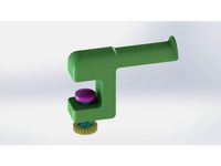
Edge Clamp Spool Holder by morganlowe
...ng. a spool holder to clamp on the edge of a desk or table. all 3d printed. fits all the spools i have ever encountered.
thanks!
thingiverse
free

Filler Jig for KING Joints by morganlowe
... joints for the larger king pre-rolls.
print upright with support everywhere on the funnel side, no support needed on the poker.
thingiverse
free
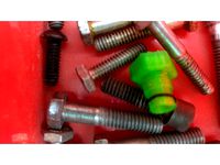
Bolt Shaped Drip Tip! by morganlowe
...eaded bolt with m12x1.25 threads for your e-cig!
see it printed here: https://youtu.be/poxalukhzve
enjoy, don't get screwed!
thingiverse
free
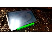
Drawing stand for Surface Pro by morganlowe
...ng. made it for my artist friend and he's loving it. uses 14 6mmx2mm round rubber feet. 10 on top 4 on the bottom.
thank you
thingiverse
free
Panasonic Toughbook CF-U1 HDD Cover by morganlowe
...s is a cover without a caddy for the cf-u1 ssd mod
just made and tested it with my mk2 cf-u1. fits and seals properly.
thank you!
thingiverse
free
Bowden Tube Bone by morganlowe
...ides snug over the tubes and just keeps them from going nuts. i might be the only person ever to need this but here it is!
enjoy!
thingiverse
free
Trowel for 50mm Concrete Curb by morganlowe
...ts in 2 parts with 3.8mm plastite screws. kinda niche but who knows, maybe you can use it! source files included, solidworks 2017
thingiverse
free

Spark Plug Inspired Drip Tip by morganlowe
...y universal. the outside hex is 19mm and it's 20mm tall without the tank nipple. it uses a 1x7mm o ring. print with support!
thingiverse
free
Spark Plug Inspired Drip Tip Tall Version by morganlowe
...:3013945
i found these print really well upside down with no support and a nice brim to stick it down. they are very thin walled.
Ramps
turbosquid
$3
Kicker Ramp - Skate Ramp
...ramp - skate ramp for download as 3ds, obj, c4d, fbx, and dae on turbosquid: 3d models for games, architecture, videos. (1153575)
turbosquid
$2
Ramp
...squid
royalty free 3d model ramp for download as obj and fbx on turbosquid: 3d models for games, architecture, videos. (1494204)
turbosquid
$5

ramp
... available on turbo squid, the world's leading provider of digital 3d models for visualization, films, television, and games.
3d_export
$5
Ramp 3D Model
...ramp 3d model
3dexport
ramp jump carjump carramp car
ramp 3d model ryisnelly100 83186 3dexport
turbosquid
$10
Ramp and Barrels
...d
royalty free 3d model ramp and barrels for download as fbx on turbosquid: 3d models for games, architecture, videos. (1263040)
turbosquid
$19
Skate Ramp
...ty free 3d model skate ramp for download as dxf, obj, and fbx on turbosquid: 3d models for games, architecture, videos. (1187602)
turbosquid
$19

Skate Ramp
...ee 3d model skate ramp for download as dxf, obj, c4d, and fbx on turbosquid: 3d models for games, architecture, videos. (1187673)
turbosquid
$80
Hydralic Ramps
... available on turbo squid, the world's leading provider of digital 3d models for visualization, films, television, and games.
turbosquid
$45
ramp door_center
... available on turbo squid, the world's leading provider of digital 3d models for visualization, films, television, and games.
turbosquid
$40
Ramp.3DS
... available on turbo squid, the world's leading provider of digital 3d models for visualization, films, television, and games.
Wire
design_connected
$11

Wired
...wired
designconnected
wired computer generated 3d model.
design_connected
$11
Wires
...wires
designconnected
wires computer generated 3d model.
design_connected
$11
Wire
...wire
designconnected
ronda design wire computer generated 3d model. designed by roccadadria, luca.
3d_export
$5
wire
...wire
3dexport
wire 180x180 cm arhive rar 3dmax2019. obj. fbx. mat corona
turbosquid
$2
HDMI wire
... 3d model hdmi wire for download as wire, wire, fbx, and wire on turbosquid: 3d models for games, architecture, videos. (1644937)
turbosquid
free
wires
...bosquid
free 3d model wires for download as ma, obj, and fbx on turbosquid: 3d models for games, architecture, videos. (1214233)
3ddd
$1

Wire chair
...wire chair
3ddd
wire chair
turbosquid
$10
wires
... available on turbo squid, the world's leading provider of digital 3d models for visualization, films, television, and games.
turbosquid
$2

Wire
... available on turbo squid, the world's leading provider of digital 3d models for visualization, films, television, and games.
3d_export
$10
wire stripper
...wire stripper
3dexport
wire stripper 5 in 1
How
3ddd
$1

Vitra / How High the Moon
...ow high the moon" японского дизайнера shiro kuramata для vitra, 1986 год.
материал - вытяжная сетка из никелированной стали.
3ddd
$1

Howe London Captain's Bar Stool
... барный
howe london captain's bar stool
dimension : w49.5 x d54.5 cm
seat height : 85 cm
base diameter : 45.8 cm
3d_export
$5

How a fireplace works in transformation animation 3D Model
...on animation 3d model
3dexport
fireplace
how a fireplace works in transformation animation 3d model first3dstudio 100328 3dexport
3d_export
$5

Toy How to Train Your Dragon 3D Model
...how to train your dragon 3d model
3dexport
toy howtotrainyourdragon
toy how to train your dragon 3d model sprut007 96434 3dexport
3d_export
free

How to Get a defind jawline
... other muscle in our body,the jaw muscles grow when stimulated by targeted training.jawline impacts facial beauty and attraction.
3d_export
free

table
...table 3dexport how poly...
3d_export
$10

broken eggs
...broken eggs 3dexport to see for yourself how refraction works, just rotate the model, paying attention to...
3d_export
$10

donut
...donut 3dexport a nice donut for u pls tell how is...
3d_export
$6

heart in cage
...heart in cage 3dexport a 3d representation of how a emotional barriers look...
3d_export
free

chair loft
...chair loft 3dexport chair loft. how poly and low poly...
1
turbosquid
$69

armchairs(1)(1)
... available on turbo squid, the world's leading provider of digital 3d models for visualization, films, television, and games.
turbosquid
$15
ring 1+1
... available on turbo squid, the world's leading provider of digital 3d models for visualization, films, television, and games.
turbosquid
$10

chair(1)(1)
... available on turbo squid, the world's leading provider of digital 3d models for visualization, films, television, and games.
turbosquid
$8

Chair(1)(1)
... available on turbo squid, the world's leading provider of digital 3d models for visualization, films, television, and games.
turbosquid
$2

RING 1(1)
... available on turbo squid, the world's leading provider of digital 3d models for visualization, films, television, and games.
turbosquid
$1
house 1(1)
... available on turbo squid, the world's leading provider of digital 3d models for visualization, films, television, and games.
turbosquid
$1

Table 1(1)
... available on turbo squid, the world's leading provider of digital 3d models for visualization, films, television, and games.
turbosquid
$59

Formula 1(1)
...lty free 3d model formula 1 for download as max, fbx, and obj on turbosquid: 3d models for games, architecture, videos. (1567088)
design_connected
$11
No 1
...no 1
designconnected
sibast no 1 computer generated 3d model. designed by sibast, helge.
turbosquid
$2
desert house(1)(1)
...3d model desert house(1)(1) for download as 3ds, max, and obj on turbosquid: 3d models for games, architecture, videos. (1055095)