Thingiverse
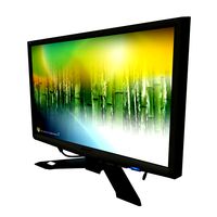
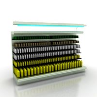
Horizontal 2.4“ TFT stand by smily77
by Thingiverse
Last crawled date: 3 years ago
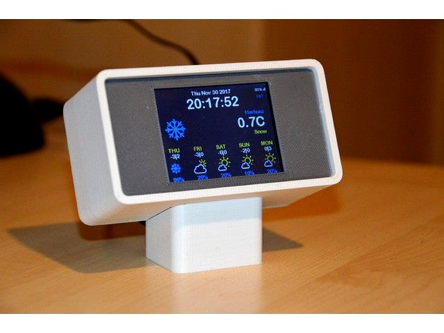
What plane is above my head, when is the next bus leaving, what is the actual exchange rate to USD, how long does it take home with the current traffic jam, ……. and of course what’s the weather tomorrow? All those and much more information’s can be fetched from the internet and displayed on your desk.
To catch such things from internet API’s become very easy with chips as an ESP8266 programmed on the Arduino IDE. But as not every maker is a master from day one, there are a lot of people offering already programmed examples in the net. They can be adapted to the own needs with only low effort. For example Dani (https://blog.squix.org/) is one of them. He has also complete kits which make the start easier for those which are not highly experienced in soldering electronics. This horizontal TFT display is based on one of them, the ESP8266 WiFi Color Display Kit 2.4″. Beside of this only 4 M3 nuts and 4 M3x20 screws are required.
IMPORTANT NOTE: I realized that I assembled the ESP8266 Wifi Color Display Kit 2.4" slightly different than it's shown in the assemble instruction video on the blog.squix.org page. Instead of using only the male pin headers for the ESP8266 module, I used the male and female pin headers (both in the kit). Please check the picture. If you are using only the male headers the hole for the reset button is wrong located and you require to rasp the connector cutout a bit.
The quite deep electronics and the power socket on the side lead to a pretty big housing. Therefore I tried to design a housing close to the style of the 80ies when the electronics was in general a bit more bulky. This brings a design with a slight vintage touch which I tried to underline with the choice of the grey and white color. I abstain from sanding or treating the plastic with acetone which leads to a texture on the front.
The front sticks to the housing but the socket (in which the power cord is hided) needs to be glued to the housing. For the distance holder on top and bottom a M3 nut needs to be pressed into the holders. The only unhappy thing is the hole for to push the reset switch of the ESP 8266 board. It can be only used if the screw on the bottom right is turned out. This as the switch is located in line with the holes for the distance holder. For the power supply cable which comes with the kit should be used as it has an pretty short stiff length.
Similar models
thingiverse
free

Squix ESP8266 WiFi Color Display Weather Station Enclosure by McuOnEclipse
...ifi-color-display-kit-2-4).
for details, see https://mcuoneclipse.com/2017/09/10/wifi-tft-touch-lcd-weather-station-with-esp8266/
thingiverse
free

ESP8266 WiFi Color Display - Weather Station Color by flipper
...s under some tabs in the case. put a little foam packing in to hold the boards in place and then press fit the back cover on it.
thingiverse
free

Weather Station Case by msurguy
...the lcd screen and snap it into the piece with the window.
close the case with the bottom piece (it should snap together nicely)
thingiverse
free

Stand For Color Weather Station from Squix by micromet
...t on 8/10/17 to better secure the base of the display in holder.
insert base first, rotate top into position, then attach screws.
thingiverse
free
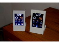
2.4" & 2.8" TFT Desktop stand by smily77
...ml (note i used a slightly different tft, a tjctm24024-spi which has the same electronics but is 2.4" instead of 2.2".)
cults
free

ESP8266 WiFi Weather Station with Color TFT Display
...utorial, files and code:
https://learn.adafruit.com/wifi-weather-station-with-tft-display/
youtube:
https://youtu.be/imep7kb_nrs
thingiverse
free

ESP8266 WiFi Weather Station with Color TFT Display by adafruit
...l tutorial, files and code:https://learn.adafruit.com/wifi-weather-station-with-tft-display/
youtube:https://youtu.be/imep7kb_nrs
thingiverse
free

ESP-F NodeMcu ESP8266 WiFi Weather Station 2.4" TFT Case
...st be spi with pins like this one, otherwise you may have wrong type of screen): https://www.aliexpress.com/item/32871767717.html
thingiverse
free

Squix ESP8266 WiFi Mini OLED Weather Station Enclosure by McuOnEclipse
...atherstation-kit-w-white-oled), see https://mcuoneclipse.com/2017/09/09/wifi-oled-mini-weather-station-with-esp8266/ for details.
thingiverse
free

2.4" TFT CASE FOR TJCTM24024 SPI DISPLAY 320x240 by abelbluelight
...he lateral. inside i have an arduino leonardo, a battery and one ieee 802.15.4 module to receive data packets. ready for sd hole.
Smily77
thingiverse
free

Wall-eyelet by smily77
...ily77
thingiverse
update #1 someboy asked me to make a horizontal one
replacement for broken wall-eyelet used in my mobile home
thingiverse
free

I2C Terminal by smily77
... provide asimple input / output possibility.
it's just a housing for a 2 line lcd 05 i2c display and 12 tactile switches 6610
thingiverse
free

EBike conversion parts by smily77
...t.
the other parts are just either mounting support or covers
parts constructed with thinkercad
ebike conversion kit: ebikekit.ch
thingiverse
free

Furniture rubber pad by smily77
... and those with a screw or nail can't be deployed everywhere.
these pads made of soft pla holds perfectly on those chairs .
thingiverse
free
bed as voucher by smily77
...t;made one" the stl couldn't be posted.
the voucher was printed with a wood filament and the stl reworked with tinkercad
thingiverse
free

35 mm film canister by smily77
...you shouldn't loose some screws, have some needles to store, ....
since everybody uses digital cams they get rarer and rarer.
thingiverse
free

Alarm Clock - Simplicity by smily77
...ration: either you what to be waked up – press button, turn for wake up time – or you don’t want the clock to ring – press button
thingiverse
free

Epaper display by smily77
...oesn’t hold that well on the bed as it’s broken. however probably it is a good idea to print it with pla instead of abs as i did.
thingiverse
free

ESP32 nano Datacenter / appliance by smily77
... for external connection of a nrf24 or lora module, is provided.
all parts stick together and hold. no glue or screws are needed.
thingiverse
free

Desktop Widget II by smily77
...s can be found here: https://hackaday.io/project/11081-forex-display. but of course this is just one possible application of many
Tft
turbosquid
$22

TFT Monitor.max
... available on turbo squid, the world's leading provider of digital 3d models for visualization, films, television, and games.
turbosquid
free

TFT monitor
... available on turbo squid, the world's leading provider of digital 3d models for visualization, films, television, and games.
turbosquid
free

TFT-Monitor_Black
... available on turbo squid, the world's leading provider of digital 3d models for visualization, films, television, and games.
3d_export
$20
TFT Screen 3D Model
...tft screen 3d model
3dexport
screen pantalla tft computer tv
tft screen 3d model mikebibby 64862 3dexport
cg_studio
$20

TFT screen3d model
...d model
cgstudio
.3ds .fbx .max .mb .obj - tft screen 3d model, royalty free license available, instant download after purchase.
turbosquid
$20

TFT computer monitor
... available on turbo squid, the world's leading provider of digital 3d models for visualization, films, television, and games.
turbosquid
$20
acer_x193w widescreen tft
... available on turbo squid, the world's leading provider of digital 3d models for visualization, films, television, and games.
3d_export
$20

TFT computer monitor 3D Model
...or 3d model
3dexport
monitor pantalla ordenador computer tft television tv
tft computer monitor 3d model mikebibby 64863 3dexport
3d_export
$20

TFT remote control 3D Model
...emote control 3d model
3dexport
tv remote tft contra mando distancia samsung
tft remote control 3d model mikebibby 64858 3dexport
turbosquid
$3

TFT Monitor 20"
... available on turbo squid, the world's leading provider of digital 3d models for visualization, films, television, and games.
Horizontal
3ddd
$1
Zephyr Horizont
...zephyr horizont
3ddd
вытяжка , zephyr
вытяжка zephyr horizont
design_connected
$13
Mr.Tubes Horizontal
...mr.tubes horizontal
designconnected
tonone mr.tubes horizontal computer generated 3d model.
3d_export
$5

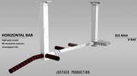
Horizontal bars
...orizontal bars
3dexport
this is a large horizontal bar for rhythmic gymnastics, as well as for pull-ups and many other exercises
3d_export
$5
Horizontal circular saw
...horizontal circular saw
3dexport
horizontal circular saw
turbosquid
$13

Horizontal tank
...id
royalty free 3d model horizontal tank for download as fbx on turbosquid: 3d models for games, architecture, videos. (1709417)
turbosquid
$1

Decor horizontal
...
royalty free 3d model decor horizontal for download as sldpr on turbosquid: 3d models for games, architecture, videos. (1256236)
3ddd
free
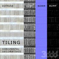
tiling horizontal decoratives
...tiling horizontal decoratives
3ddd
штукатурка
tiling horizontal decorative texture
turbosquid
$19

The horizontal bar
... model the horizontal bar for download as , fbx, stl, and obj on turbosquid: 3d models for games, architecture, videos. (1684719)
turbosquid
$10

Horizontal Bar
...ree 3d model horizontal bar for download as max, obj, and fbx on turbosquid: 3d models for games, architecture, videos. (1435728)
turbosquid
$15
Horizontal Bar
...d model horizontal bar for download as 3ds, max, obj, and fbx on turbosquid: 3d models for games, architecture, videos. (1317823)
Stand
turbosquid
$50

stand watermelon stand
...yalty free 3d model stand watermelon stand for download as ma on turbosquid: 3d models for games, architecture, videos. (1528284)
archibase_planet
free
Stand
...stand
archibase planet
stand post pole
stand - 3d model for interior 3d visualization.
archibase_planet
free

Stand
...stand
archibase planet
stand sport barbell
stand kettler - 3d model for interior 3d visualization.
archibase_planet
free
Stand
...stand
archibase planet
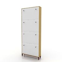
locker drawer stand
stand 897810 - 3d model for interior 3d visualization.
archibase_planet
free
Stand
...stand
archibase planet
stand rack post
stand 2 - 3d model for interior 3d visualization.
archibase_planet
free
Stand
...stand
archibase planet
stand storefront shelving
stand 3 - 3d model for interior 3d visualization.
archibase_planet
free
Stand
...stand
archibase planet
stand shelf shelving
stand 4 - 3d model for interior 3d visualization.
archibase_planet
free
Stand
...stand
archibase planet
stand post stall
stand 5 - 3d model for interior 3d visualization.
archibase_planet
free
Stand
...stand
archibase planet
stand post stall
stand 6 - 3d model for interior 3d visualization.
archibase_planet
free
Stand
...stand
archibase planet
stand post shelving
stand 7 - 3d model for interior 3d visualization.
4“
turbosquid
$9

Office Chair 4-4
... available on turbo squid, the world's leading provider of digital 3d models for visualization, films, television, and games.
3d_export
$5

doors- 4
...doors- 4
3dexport
doors 4
3d_export
$5

hinge 4
...hinge 4
3dexport
hinge 4
3ddd
$1

Штора №4
...штора №4
3ddd
штора №4
3d_export
free

playstation 4
...playstation 4
3dexport
playstation 4
turbosquid
$1
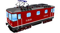
re 4-4 electric locomotive
... free 3d model re 4 4 electric locomotive for download as obj on turbosquid: 3d models for games, architecture, videos. (1707845)
3ddd
$1
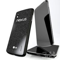
nexus 4
...nexus 4
3ddd
lg , телефон
nexus 4
3ddd
$1
4 Poufs
...4 poufs
3ddd
пуф
4 soft poufs
turbosquid
$12

Calligraphic Digit 4 Number 4
...hic digit 4 number 4 for download as max, obj, fbx, and blend on turbosquid: 3d models for games, architecture, videos. (1389332)
3ddd
$1
Dauphin 4+
...dauphin 4+
3ddd
кресло
dauphin 4+ конференц кресло
2
design_connected
$11
No 2
...no 2
designconnected
sibast no 2 computer generated 3d model. designed by sibast, helge.
turbosquid
$6
Cliff Rock 2-2
...uid
royalty free 3d model cliff rock 2-2 for download as obj on turbosquid: 3d models for games, architecture, videos. (1619161)
turbosquid
$29

Book variation 2 2
...3d model book variation 2 2 for download as max, obj, and fbx on turbosquid: 3d models for games, architecture, videos. (1366868)
turbosquid
$22
Classic baluster (2) (2)
...assic baluster (2) (2) for download as max, obj, fbx, and stl on turbosquid: 3d models for games, architecture, videos. (1483789)
turbosquid
$99

Smilodon 2 Pose 2
... available on turbo squid, the world's leading provider of digital 3d models for visualization, films, television, and games.
turbosquid
$20

Barrel Barricade 2-2
... available on turbo squid, the world's leading provider of digital 3d models for visualization, films, television, and games.
turbosquid
$6
Wall Trophy (2) (2)
... available on turbo squid, the world's leading provider of digital 3d models for visualization, films, television, and games.
turbosquid
free
Tire label 2 of 2
... available on turbo squid, the world's leading provider of digital 3d models for visualization, films, television, and games.
3ddd
$1

Кровать, 2 тумбочки, 2 светильника
...кровать, 2 тумбочки, 2 светильника
3ddd
кровать, 2 тумбочки, 2 светильника
нормальное качество
формат 3ds max
без текстур
3ddd
free

Кровать, 2 тумбочки, 2 светильника
...кровать, 2 тумбочки, 2 светильника
3ddd
кровать, 2 тумбочки, 2 светильника
нормальное качество
формат 3ds max
без текстур