GrabCAD
HIGH EFFICIENCY NASA WIND TUNNEL
by GrabCAD
Last crawled date: 1 year, 10 months ago
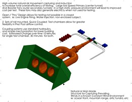
NASA TRANSONIC WIND TUNNEL DESIGN.
DESIGNED BY JC BIGGS
The overall goal of this design is to accomplish interchangeability with simple current existing technologies and ground equipment to keep cost low. All mechanics can be motor or hydraulic driven. The rail based interchange track allows movement away from the tunnel for new designs to be loaded onto the trolleys, or more trolleys added. The nature of the rail system gives you a substantial amount of space to load many test chamber designs.
I also wanted to take into account efficiency of the air flow. to my knowledge no one has built a wind tunnel that takes advantage of Bernoulli/Coanda Effects and inducement and entrainment, (I could be wrong on this, I didn't do much research) while this technology is well known in other industries that require mass air movement. (Dyson bladeless fan for instance uses 20cfm to move 300) In addition to the Coanda effect, placing the tunnel in a air wind region assist with further decreasing the energy required for further accelerations. With fan staging, my thought process is that you could increase static pressure to the point that you don't need as much power input to the fans to achieve the desired velocities in the test chamber, while minimizing the impact of prevailing wind variability.
I also believe that having 2 interchangeable chambers in series, better allows the engineers to optimize flow dynamics, Chamber design, and pre/post test subject conditions. This should lead to overall more accurate results with less testing required. The design also allows for "transitional" designs. For instance, if you want to move from a Cylindrical chamber to a rectangular one. You now have the ability to transition that flow profile as required.
Finally I wanted the chamber to be open air. Avoiding needs for post test cooling, and the associated boundary drag with pushing air around a loop. While adding the ability to do things like live engine testing, or Non-contained Model testing (ie, the tunnel blowing onto a model, but the model situated outside the end of the chamber in open air,) or adding water injection to simulate Mach 1 Rain performance. You could also inject debris for Dust testing,
Data aquisition and model fixturing will be built into the trolley system. For standard Test Module Designs, this would be a permanent mounting fixture protruding through the "tube"
Thanks for the opportunity. This was fun thing to model.
Similar models
grabcad
free

Interchangeable wind tunnel test section
...interchangeable wind tunnel test section
grabcad
nasa challenge of transonic wind tunnel test section
grabcad
free

NASA Challenge: New Transonic Wind Tunnel Test Section
... an air purifier to purify the air with a low-cost model. hope this system works efficiently and helps in its respective purpose.
grabcad
free

Nasa Challenge : Wind Tunnel Test Section
...lenge. the exact required dimensions are implemented here. a crane is also designed to put the rockets or planes into the tunnel.
grabcad
free

Model Coupling Mechanism for NASA Transonic Wind Tunnel
...ve for the future of wind tunnel tests would be substantial.
further details on this design are included with the attached pdf.
grabcad
free

NASA Wind Tunnel Facility
...this design is the choice and improves operational and human factors in the wind tunnel facility and supports wind tunnel tests .
grabcad
free

NASA model wind tunnel
...rage space, than circular rotating loading systems.
25. double operators room, to be able to work independently each test chamber
grabcad
free

Test Section with Automated Driving Interchangeable Platform.
...actors in a wind tunnel facility and support future wind tunnel tests required over the next several years.
good luck to all !!!
grabcad
free

NASA Challenge: concept for Wind Tunnel Test Section
...ment the concept on existing wind tunnels. ideally, the modular elements should be interchangeable between the different tunnels.
grabcad
free

TRANSONIC WIND TUNNEL TEST SECTION
...ocus on construction of transonic wind tunnel test section, available space design and required technology with work flow method.
grabcad
free

NASA Wind Tunnel Challenge
...zation of the wind tunnel testing process.
i will upload all individual models and assemblies after the compitition is complete.
Tunnel
grabcad
free

Tunnel
...tunnel
grabcad
ear tunnel
grabcad
free

Tunneler
...tunneler
grabcad
medical tunneler for vein extraction
grabcad
free

Mine tunnel
...mine tunnel
grabcad
mine tunnel
grabcad
free

Tunnel pulvérisation
...tunnel pulvérisation
grabcad
tunnel pulvérisation
grabcad
free

Rotating tunnel
...rotating tunnel
grabcad
rotating tunnel
grabcad
free

tunnel dome
...tunnel dome
grabcad
tunnel dome
grabcad
free

Tunnel shutter
...tunnel shutter
grabcad
tunnel formwork
grabcad
free

Wind Tunnel
...wind tunnel
grabcad
wind tunnel
grabcad
free

tunnel job
...tunnel job
grabcad
tunnel job
grabcad
free

heat tunnel
...heat tunnel
grabcad
heat tunnel
Nasa
grabcad
free

NASA
...nasa
grabcad
nasa
grabcad
free

NASA
...nasa
grabcad
nasa challenge
grabcad
free

Nasa
...nasa
grabcad
para desafio nasa
grabcad
free

Nasa
...nasa
grabcad
challenge
grabcad
free

NASA
...nasa
grabcad
x
grabcad
free

NASA Challenge
...nasa challenge
grabcad
nasa challenge
grabcad
free

NASA Challenge2
...nasa challenge2
grabcad
nasa challenge2
grabcad
free

NASA ROBOT
...nasa robot
grabcad
nasa robot
grabcad
free

NASA Handrail
...nasa handrail
grabcad
design for nasa
grabcad
free

NASA Gas
...nasa gas
grabcad
nasa gas
Wind
grabcad
free

wind
...wind
grabcad
wind
grabcad
free

Wind Pump
...wind pump
grabcad
wind pump use for wind generation
grabcad
free

Wind Sock
...wind sock
grabcad
wall mount wind sock to indicate the wind direction.
grabcad
free

Wind Turbine
...wind turbine
grabcad
the wind turbine is used to extract power from wind energy..
grabcad
free

Wind Turbine
...nd turbine designed by solidworks. a wind turbine is a device that converts the wind's kinetic energy into electrical energy.
grabcad
free

wind
...wind
grabcad
ow
grabcad
free

Wind
...wind
grabcad
for fiver
grabcad
free

wind turbine
...wind turbine
grabcad
wind turbine it is a machine that extarct the energy from wind to convert it to electricity
grabcad
free

Wind Turbine
...wind turbine
grabcad
a wind turbine is a device that converts the kinetic energy of wind into electrical energy.
grabcad
free

Wind Türbine
...wind's kinetic energy into electrical energy. wind turbines are manufactured in a wide range of vertical and horizontal axis.
Efficiency
grabcad
free

Cyclone High efficiency
...cyclone high efficiency
grabcad
high efficiency stairmand cyclone
grabcad
free

Energy Efficient Cookware
...energy efficient cookware
grabcad
energy efficient cooking pot
grabcad
free

Energy efficient light bulb
...energy efficient light bulb
grabcad
energy efficient light bulb
grabcad
free

Vision Efficient Dynamic
...vision efficient dynamic
grabcad
10 hours of rendering
grabcad
free

Energy efficient electromagnetic motor
...energy efficient electromagnetic motor
grabcad
i managed to build an energy-efficient electromagnetic motor
grabcad
free

Vision Efficient Dynamics
...vision efficient dynamics
grabcad
software used:- catiav5 n photoshop
grabcad
free

Energy Efficient Light Bulb
...energy efficient light bulb
grabcad
an energy efficient light bulb designed as part of my training with inventor 2020
grabcad
free

Efficient Hull Design
...teknik hull design competition. the calculations for the hull efficiency were done using an excel spreadsheet based on the...
grabcad
free

global efficiency energy now
... this matrix.
local cooling already.
gas | coal | biomass -> energy -> heat -> cold to hvac and outsourcing datacenter
grabcad
free

NASA cruise efficient STOL aircraft
...nasa cruise efficient stol aircraft
grabcad
nasa cruise efficient stol aircraft concept
High
grabcad
free

high table with black high chair
...high table with black high chair
grabcad
high table with black high chair
grabcad
free

High power high torque servo
...high power high torque servo
grabcad
high power servo. goes by asme or dh-x names.
grabcad
free

High chair
...high chair
grabcad
high chair
grabcad
free

PERFUME-HIGH
...perfume-high
grabcad
perfume-high
grabcad
free

High Chair
...high chair
grabcad
high chair
grabcad
free

High table
...high table
grabcad
high table
grabcad
free

High chair
...high chair
grabcad
high chair
grabcad
free

High chair
...high chair
grabcad
high chair
grabcad
free

High ArmChair
...high armchair
grabcad
high armchair
grabcad
free

High heel
...high heel
grabcad
pair of high heels