Thingiverse

HexaMicroFly by reparator
by Thingiverse
Last crawled date: 3 years, 1 month ago
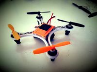
The answer to all the quadrocopter designs: The HexaMicroFly !!!
This is the video: https://www.youtube.com/watch?v=ZvVWfrv91e8
I like Punkkills Micro 105 FPV Quadrocopter design (http://www.thingiverse.com/thing:1221911) and I wanted to build one. But in Germany you need special frequences for RC flighing which are not covered by the Micro Scisky or the Eachine Flight Controllers with reveiver build-in. So I ordered a SP3Racing Evo with a separate RM receiver from banggood. They send me a SPRacingEvo V2.0 which has outputs for six motors. So I decided to build up a hexacopter. Here is the printable design for it:
What you need:
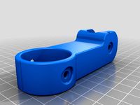
frame (3D printed): HexaFrame.stl
top (3D printed): TopV2_05.stl or TopV1_04.stl
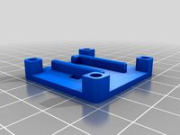
optional: Flightcontroller Case: FCCase.stl
6x brushed motors 8.5 mm (3x clockwise, 3x counterclockwise)
FrSky Ultra Light XM Receiver Up To 16CH
or
Frsky XM+ Micro D16 SBUS Full Range Receiver Up to 16CH
Micro 32bits F3 Brushed Flight Control Board Based On SP RACING F3 EVO Brush
5V Buzzer Alarm Beeper
LED Strip Light Board
Nylon Screws
Some connectors for easier build-up:
Mini Micro JST 1.5mm ZH 2-Pin Connector Plug With Wires
Walkera QR Ladybird Blades Propellers
For the FPV:
AIO 5.8G VTX + FPV Camera PAL/NTSC
I used Fatshark dominator V3 glasses with Nexwave 5G8 Race Band receiver module.
Instruction:
All parts printed in PETG from DasFilament in safety yellow color.
Infill: 25 %, no support
2 perimeters in vertical shell
2 perimeters in top and buttom shell
There are two versions of the top. One without cover for the camera (Top04), one with camera protection (TopV2_05).
The top parts get screwed together with the main frame with 20 mm nylon bolts and nuts as you can see on the pictures.
The flightcontroller can by glued with low temperature hotmelt glue into the optional flightcontroller case (Part PCCase) to obtain a better protection and stability.
Cut some 40-50 mm long pieces of the wired connector plugs and solder them to the motor cables. Don´t forget to isolate with heat-shrink tubing. Solder the JST 1.5mm ZH 2-Pin connectors to the motor outputs of the flight controller board (marked with M1 to M6). So the motors are easier to change in case of damage.
As firmware I used cleanflight.
One disadvantage of the design of the frame is, that the two rotors in front are always part of the video capture. So the frame has to be modified.
All these information come without any warrenty. Use this description at your own risk!
This is the video: https://www.youtube.com/watch?v=ZvVWfrv91e8
I like Punkkills Micro 105 FPV Quadrocopter design (http://www.thingiverse.com/thing:1221911) and I wanted to build one. But in Germany you need special frequences for RC flighing which are not covered by the Micro Scisky or the Eachine Flight Controllers with reveiver build-in. So I ordered a SP3Racing Evo with a separate RM receiver from banggood. They send me a SPRacingEvo V2.0 which has outputs for six motors. So I decided to build up a hexacopter. Here is the printable design for it:
What you need:
frame (3D printed): HexaFrame.stl
top (3D printed): TopV2_05.stl or TopV1_04.stl
optional: Flightcontroller Case: FCCase.stl
6x brushed motors 8.5 mm (3x clockwise, 3x counterclockwise)
FrSky Ultra Light XM Receiver Up To 16CH
or
Frsky XM+ Micro D16 SBUS Full Range Receiver Up to 16CH
Micro 32bits F3 Brushed Flight Control Board Based On SP RACING F3 EVO Brush
5V Buzzer Alarm Beeper
LED Strip Light Board
Nylon Screws
Some connectors for easier build-up:
Mini Micro JST 1.5mm ZH 2-Pin Connector Plug With Wires
Walkera QR Ladybird Blades Propellers
For the FPV:
AIO 5.8G VTX + FPV Camera PAL/NTSC
I used Fatshark dominator V3 glasses with Nexwave 5G8 Race Band receiver module.
Instruction:
All parts printed in PETG from DasFilament in safety yellow color.
Infill: 25 %, no support
2 perimeters in vertical shell
2 perimeters in top and buttom shell
There are two versions of the top. One without cover for the camera (Top04), one with camera protection (TopV2_05).
The top parts get screwed together with the main frame with 20 mm nylon bolts and nuts as you can see on the pictures.
The flightcontroller can by glued with low temperature hotmelt glue into the optional flightcontroller case (Part PCCase) to obtain a better protection and stability.
Cut some 40-50 mm long pieces of the wired connector plugs and solder them to the motor cables. Don´t forget to isolate with heat-shrink tubing. Solder the JST 1.5mm ZH 2-Pin connectors to the motor outputs of the flight controller board (marked with M1 to M6). So the motors are easier to change in case of damage.
As firmware I used cleanflight.
One disadvantage of the design of the frame is, that the two rotors in front are always part of the video capture. So the frame has to be modified.
All these information come without any warrenty. Use this description at your own risk!
Similar models
thingiverse
free

120mm Quadcopter frame by MarcoDesigns
...jh57cxa
battery/s: https://www.stefansliposhop.de/akkus/sls-spielzeugakkus-spezialakkus/sls-xtron-600mah-1s1p-3-7v-20c::1579.html
thingiverse
free

Hexacopter Frame with FPV by albydnc
...hexacopter frame with fpv by albydnc
thingiverse
hexacopter frame for 0612 motors and f3 evo flight controller.
thingiverse
free

Micro FPV Quad Frame by jason51873
...ponents used:
8.5mm brushed motors
beef's brushed board
microfrx receiver - frsky compatible
hyperion quanum elite camera/vtx
thingiverse
free

XF 95 by TEAJR66
...ound the evo f3 flight controller, such as the ones in the qx80 and qx90. the fc snaps into place and is held secure by the tabs.
thingiverse
free
DC110 ABS ACRO for SP F3 RACING EVO Brush Flight Control by Microdure
...90-qx95-naze32-f3-diy-micro-brushed-fpv-racer-p-1100338.html?p=ld020411878172015024
good fun
https://www.facebook.com/microdure/
thingiverse
free

Simple 720 motor hexacopter by Iwanestem
...l-board-based-on-sp-racing-f3-evo-for-micro-fpv-frame-p-1076530.html?rmmds=detail-left-hotproducts__1&cur_warehouse=cn
thanks
thingiverse
free
FRsky XM+ Mount 36mm by didymus
...ou'd like.
xm+ purchased here: https://www.banggood.com/frsky-xm-micro-d16-sbus-full-range-receiver-up-to-16ch-p-1110020.html
thingiverse
free

Micro H-Quadcopter add ons by JeWa
...quadcopter add ons by jewa
thingiverse
these accessories are tested with the flight controller f3 evo brushed flight controller.
cults
free

DC110 ABS ACRO for SP F3 RACING EVO Brush Flight Control
...x95-naze32-f3-diy-micro-brushed-fpv-racer- p-1100338.html? p = ld020411878172015024
good fun
https://www.facebook.com/microdure/
thingiverse
free

Beetle micro quadcopter frame (brushed motors) by mfazio_science
...ww.banggood.com/eachine-tx01-super-mini-aio-5_8g-40ch-25mw-vtx-600tvl-14-cmos-fpv-transmitter-p-1088374.html?x709229380619201703o
Reparator
thingiverse
free

Medaille reparer by Kenzay62
...medaille reparer by kenzay62
thingiverse
medaille reparer
thingiverse
free

Medaille repared by Kenzay62
...medaille repared by kenzay62
thingiverse
medaille repared
thingiverse
free

Eu Adapter Reparation by AndresVH
...eu adapter reparation by andresvh
thingiverse
used for the reparation of a broken adapter with eu plug
thingiverse
free

VesaAdapter75to100 by reparator
...vesaadapter75to100 by reparator
thingiverse
vesa-adapter 75x75 mm to 100 x 100 mm.
thingiverse
free

suport colle repar-EX by mactiti
...suport colle repar-ex by mactiti
thingiverse
suport colle repar-ex + accessoirs
thingiverse
free

Toaster repar part by sellemann
...toaster repar part by sellemann
thingiverse
print toast enjoy
thingiverse
free

Goldfinger reparation by wennes
...goldfinger reparation by wennes
thingiverse
if you want to lie in your bed like james bond...
https://youtu.be/gkn4kcahcei
thingiverse
free

ArduinoBreadboardAdapter by reparator
... not sufficient. the arduino is hold in place with bolds and clips.
lost junction and flying wires are a thing of the past now...
thingiverse
free
babychair repair ( reparation chaise haute ) by franck
...babychair repair ( reparation chaise haute ) by franck
thingiverse
thingiverse
free

Anti-Gravitator by reparator
...lso called levitator or levitron. it lets a small magnet sphere levitate in a magnetic field.
video: https://youtu.be/0ftbobwkf2y