GrabCAD
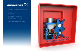
Grundfos Grunty Hydronic Valve
by GrabCAD
Last crawled date: 1 year, 11 months ago
Final assembly attached.
Total reduction ratio of 900:1, (900:30:15:2:1).
Stage 1: 30:1, Size 8, CSF-1U-CC, HarmonicDrive reducer, 70% nominal efficiency.
Stage 2: 1:1, 25 Tooth, KHK spiral miter gear transfer, 97% nominal efficiency.
Stage 3: 45:3 KHK hypoid gear set, 86% nominal efficiency
Stage 4: 24:48 KHK ground helical spur coupled to output shaft, 97% nominal efficiency.
Output torque approximately = 0.040Nm (@900rpm) x 900 x 0.58(Total efficiency) = 20.4Nm
The gear box can be customised in several ways including at the HarmonicDrive where the unit is available in 30, 50 and 100 ratios. The output spurs can also be varied from 1:1 through to 2:1. This would allow for a range between 450-1500:1. As described below, a motor of higher torque can be accommodated in the same space.
All transfer components are available off the shelf and specified to the correct tolerance and torque capability. Bearings supplied by AST and SKF. BOM references attached.
Should the HarmonicDrive unit prove costly, a generic of the same type is available through 3F Famed.
I've also included mount holes for an uprated equivalent stepper motor. The quoted stepper assumed to be a TSM35-5V type can be replaced with a TSM42-5V providing upto 50% more torque. The alternative still fits within the build envelope.
Some secondary machining of standard items would be required. The hypoid pinion is supplied with ample stock for axle machining. The initial primary bevel gear has a bore of 8mm while the HarmonicDrive unit has a D axle of 9mm, manufacturer should be able to customise the ouput shaft to suit.
Bearings have been chosen to accommodate radial and axial thrust loads.
Some additional hardware, such as shims and washers have not been included for lack of time and appropraite tolerancing. Also, shaft keys would need to be added for output shafts.
Although stress analysis is not yet provided, the top plate of the last two output stages, in conjunction with the enclosure body standoffs and mounting hardware, will support the prerequisite loads.
I've included some draft in the mounting standoffs for molding purposes.
Additional mounts for the rest of the stages can be produced in appropriate plastic or extruded alumium for best tolerance.
Ball bearings at all load points ensure long life.
Added an exploded animation and BOM.
Thank you to Grundfos for posing the challenge, it certainly had my brain churning,
Update: Added an alternate first stage bracket which may simplify manufacturing.
Similar models
grabcad
free

Grundfos Challenge Cycloid Gearbox
...s 19,96 nm.
more details are given in the design-report.
a special thanks to the grabcad-users giving me tips for the design!
grabcad
free

Grundfos Challenge Enclosure Box
...rings so that efficiency can be maximized.
3. all components can be arranged on the z axis.
4. maintenance free.
5. high lifetime
grabcad
free

Grundfos Challenge - Mattia Cestaro
...43mnm
gear ratio:
509
output result:
rotation speed: 0.98rpm
torque: 20 nm
(considered an efficiency of 90% for a spur gearbox)
grabcad
free

Grundfos Challenge (version 1)
...ateral clearance in two stages to obtain a given hysteresis value on the output shaft.
see more description in attached files...
grabcad
free

Grundfos- Gear Box Challenge
...eign .
all value correct calculation for gears ..
the assembly type of gear units is mounted in the enclosure the z-direction..
grabcad
free

Grundfos challenge harmonic drive
...o mounting holes from the top or size of both spur gears can be increased and cut outs in spur gear will allow bolt installation.
grabcad
free

Gear box with Spur gear, Z axis assembly
...ifferent gears), 4 no of smooth 4 mm shafts for gears, 2 spacers( bush),one bearing and screws for mounting motor and top cover.
grabcad
free

Grundfos Design Challenge
...allenge
grabcad
two-stage gear train: 1st stage, planetary; 2nd stage, spur
gear ratio = 22.2 : 1 (see attached doc for details)
grabcad
free

One stage reducer
... i=3.15
number of teeth :
z1=17 (gear one)
z2=54 (gear two)
output:
rpm =476 (on the exit shaft)
output torque == 421nm (aprox.)
grabcad
free

GC Gear Box - Worm Gear + Spur Gear
...from high quality brands like misumi and mc mcmaster-carr, with the finale of reduce manufacturing cost and reduce the lead time.
Hydronic
grabcad
free

Gear train for Hydronic Valve
...gear train for hydronic valve
grabcad
gear train for hydronic valve
grundfos challenge
grabcad
free

hydronic Baseboard
...hydronic baseboard
grabcad
model of an american style standard baseboard, used in many houses and buildings
grabcad
free

LARRS HYDRONIC BOILER
...larrs hydronic boiler
grabcad
model nth 750
grabcad
free

Hydronic Valve Gear
...hydronic valve gear
grabcad
retio i=744,187 output torque is 29 nm & 1 rpm.
grabcad
free

Gear unit for a hydronic valve
...gear unit for a hydronic valve
grabcad
compound gear system is used.
grabcad
free

Hydronic valve gear unit
...hydronic valve gear unit
grabcad
900:1 compound worm & wheel set
grabcad
free

Hydronic Valve Gear Set - V1
...hydronic valve gear set - v1
grabcad
the gear set fits in the enclosure box the output torque is 51 nm & 3 rpm.
grabcad
free

WJDAE - TOKSC Hydron
...ther entry:
https://grabcad.com/library/wjdae-toksc-mechscrew-1
don't forget to hit "♥" button before you leave :)
grabcad
free

"Hydrone" Parcel Delivery Drone
...eight high above ground, delivery can be achieved. this versatility marks the hydrone as a workhorse, for the logistics industry.
grabcad
free

Belt Driven Hydronic Valve Actualtor
...ulley for a global reduction ratio of 536:1.
the system needs no maintenance. it is lubrication free and it has high reliability
Grundfos
grabcad
free

LOGO GRUNDFOS
...logo grundfos
grabcad
logotipos grundfos
grabcad
free

Grundfos Pump
...grundfos pump
grabcad
grundfos pump cr 64-3
grabcad
free

Grundfos Pump
...grundfos pump
grabcad
grundfos pump cr 64-3
grabcad
free

Grundfos Challenge
...grundfos challenge
grabcad
grundfos challenge: design and integration of a gear unit for a hydronic valve into an enclosure box
grabcad
free

Bomba Grundfos cr15
...bomba grundfos cr15
grabcad
bomba grundfos cr15
grabcad
free

Pressurizer Grundfos Scala2
...pressurizer grundfos scala2
grabcad
pressurizer grundfos scala2
grabcad
free

Grundfos Challenge 2019
...grundfos challenge 2019
grabcad
my approach on the grundfos challenge 2019
grabcad
free

Grundfos Pump
...grundfos pump
grabcad
feed pump
grabcad
free

Grundfos UPS25-80N
...grundfos ups25-80n
grabcad
just 3d model circulator pump grundfos ups25-80n
grabcad
free

GRUNDFOS COOLANT PUMP
...grundfos coolant pump
grabcad
grundfos coolant pump
cr 3-5 a-fgj-a-v-hqqv
Valve
grabcad
free

VALVE
...valve
grabcad
valve of a stop valve body
grabcad
free

valve of stop valve
...valve of stop valve
grabcad
valve of a stop valve with drafting and file converted into pdf with png image of drafting.
grabcad
free

Valve
...alve
grabcad
a gate valve, also known as a sluice valve, is a valve that opens by lifting a barrier out of the path of the fluid
grabcad
free

valve
...afety valves, and vacuum pressure safety valves.
safety valves were first used on steam boilers during the industrial revolution
grabcad
free

valve
...valve
grabcad
valve
grabcad
free

valve
...valve
grabcad
valve
grabcad
free

valve
...valve
grabcad
valve
grabcad
free

Valve
...valve
grabcad
valve
grabcad
free

Valve
...valve
grabcad
valve
grabcad
free

Valve
...valve
grabcad
valve