Thingiverse
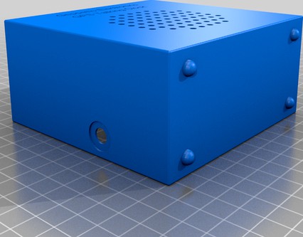
GPS Talking Clock case
by Thingiverse
Last crawled date: 4 years, 3 months ago
This is a 3D printed case for https://hackaday.io/project/28949-gps-talking-clock .
Solder wires onto the speaker, button and volume control first.
Place the speaker into the front and screw it down with 4 #4 3/16" self-tapping pan head screws.
Insert the button into the big hole at the top of the front.
Insert the volume control into the back and fasten it with the washers and nut it came with. Attach a knob to the shaft.
If you haven't already done so, attach the 4 DIP switch block to the back of the board.
Solder the wires from the speaker, button and volume control to the board. For the volume control, make sure to attach the wires in the correct order.
Now would be a good time to test the board. Plug in an antenna and power and adjust the volume control about a quarter way up from the CCW end. Wait a few seconds after the GPS LED starts blinking and push the button. You should hear the clock talk.
Attach the board to the back panel with 4 #4 3/8" pan head self-tapping screws.
Attach the back panel to the front with 4 more #4 3/8" pan head self-tapping screws.
Similar models
thingiverse
free

GPS Clock case
...g the two together, turn the assembly around and secure the two halves together with 4 #4 3/8" pan head self-tapping screws.
thingiverse
free
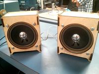
Laser Cut 4" Speaker Case by Bartimaeus
... that are 3/8" long and the matching nuts.
speakers used: http://www.digikey.com/product-detail/en/gf1004/gf1004-nd/304447
thingiverse
free

Speaker with penrose grill
...ued onto the middle part. screw holes in the middle section need to be tapped for m3 then the back can be affixed with m3 screws.
thingiverse
free
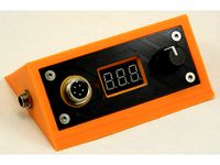
Case for soldering station with T12 tips by Nick_Shl
... it. in result, you will be able to detach/attach front panel from the board. use four m3 screws to fix front panel to the prism.
thingiverse
free

Full Graphic Smart Controller Case by RC_CnC
...ount lcd with the remaining 4) m3x8 button head screws.
with this design, other mounting brackets can be screwed to back of case.
thingiverse
free

Control Panel Mount Bracket by TheDreamMaster
...a length of 11-12mm should be safe, perhaps 3/8"to 7/16".
the screws i used are 2.9mm in diameter and 11.5mm in length.
thingiverse
free

Maiskolben Case by Zellech
...omponents:
screw: 6x pan-head flat head screw 3x10
glue: to connect part 6 with part 5, part 7 with part 4 and part 8 with part 1
grabcad
free

Small 2,2x8 mm Pan head screw
...small 2,2x8 mm pan head screw
grabcad
self tapping pan head screw
diameter: 2,2 mm
length: 8 mm
drive: philips
grabcad
free

M3x10 Screw Self-Tapping Tribulor Button Head
...m3x10 screw self-tapping tribulor button head
grabcad
m3x10 screw self-tapping tri-bulor button head
thingiverse
free
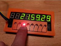
Case for JY-MCU JY-LKM1638 "8x digital tube LED module" with TM1638 by rodmod
...clear solder joints on the back of the board.
to assemble, put the case front face down, insert the module, then put the back on.
Talking
turbosquid
$3

talking skull
...quid
royalty free 3d model talking skull for download as c4d on turbosquid: 3d models for games, architecture, videos. (1199796)
turbosquid
$99

Talking Skull
... available on turbo squid, the world's leading provider of digital 3d models for visualization, films, television, and games.
turbosquid
$5

Talking Drum
...ing drum for download as blend, blend, 3ds, dae, fbx, and obj on turbosquid: 3d models for games, architecture, videos. (1593408)
3d_export
$10

Talk sack 3D Model
...talk sack 3d model
3dexport
sack bag talk funny potato animation
talk sack 3d model helios 12933 3dexport
turbosquid
$25

Leds C4 TALK
... free 3d model leds c4 talk for download as 3ds, obj, and fbx on turbosquid: 3d models for games, architecture, videos. (1689922)
turbosquid
$4

Wood talk woodzzz
... 3d model wood talk woodzzz for download as max, fbx, and obj on turbosquid: 3d models for games, architecture, videos. (1658630)
turbosquid
$100

Talking Head - 01
... available on turbo squid, the world's leading provider of digital 3d models for visualization, films, television, and games.
turbosquid
$59

Animated Talking Humans
... available on turbo squid, the world's leading provider of digital 3d models for visualization, films, television, and games.
turbosquid
$5

Sevi - talking dreidel
... available on turbo squid, the world's leading provider of digital 3d models for visualization, films, television, and games.
3d_ocean
$19

Cartoon Talking Cat
...for cartoon games. due to the optimization of textures and animations and a small amount of triangles, this model can be used ...
Gps
3ddd
free
Подавитель GPS
...подавитель gps
3ddd
подавитель gps
3ddd
free

Подавитель GPS
...подавитель gps
3ddd
подавитель gps
3ddd
free

Cтол GP
...cтол gp
3ddd
обеденный , giorgio piotto
cтол gp
turbosquid
$5
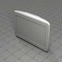
GPS navigation
...e 3d model gps navigation for download as blend, fbx, and obj on turbosquid: 3d models for games, architecture, videos. (1636695)
turbosquid
$4
GP-5
...lty free 3d model gp-5 for download as 3ds, max, obj, and fbx on turbosquid: 3d models for games, architecture, videos. (1160699)
turbosquid
$60
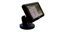
TomTom GPS
... available on turbo squid, the world's leading provider of digital 3d models for visualization, films, television, and games.
turbosquid
free

GPS/TV
... available on turbo squid, the world's leading provider of digital 3d models for visualization, films, television, and games.
3d_export
$5

Battery GP 3D Model
...battery gp 3d model
3dexport
battery gp
battery gp 3d model wasiliy 40319 3dexport
3d_export
$5

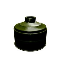
gas mask gp-5
...gas mask gp-5
3dexport
gas mask gp-5
cg_studio
$36

Gps device3d model
...ice3d model
cgstudio
.3ds .c4d .dxf .obj - gps device 3d model, royalty free license available, instant download after purchase.
Clock
3d_ocean
$4

Clock
...clock
3docean
clock hand kitchen clock time watch
a clock
archibase_planet
free

Clock
...clock
archibase planet
clock table clock alarm-clock
clock orange - 3d model (*.gsm+*.3ds) for interior 3d visualization.
archibase_planet
free

Clock
...clock
archibase planet
clock table clock alarm-clock
clock yellow - 3d model (*.gsm+*.3ds) for interior 3d visualization.
archibase_planet
free
Clock
...clock
archibase planet
clock alarm-clock
clock n100707 - 3d model for interior 3d visualization.
archibase_planet
free

Clock
...clock
archibase planet
clock table clock
clock - 3d model (*.gsm+*.3ds) for interior 3d visualization.
archibase_planet
free

Clock
...clock
archibase planet
clock striking clock
clock - 3d model (*.gsm+*.3ds) for interior 3d visualization.
archibase_planet
free

Clock
...clock
archibase planet
clock wall clock
clock 1 - 3d model (*.gsm+*.3ds) for interior 3d visualization.
archibase_planet
free
Clock
...clock
archibase planet
clock wall clock
clock 2 - 3d model (*.gsm+*.3ds) for interior 3d visualization.
archibase_planet
free

Clock
...clock
archibase planet
clock wall clock
clock 3 - 3d model (*.gsm+*.3ds) for interior 3d visualization.
archibase_planet
free

Clock
...clock
archibase planet
alarm clock alarm-clock
clock - 3d model (*.gsm+*.3ds) for interior 3d visualization.
Case
3d_export
$1
case
...case
3dexport
case
archibase_planet
free
Case
...case
archibase planet
showcase show-case glass case
glass-case + cakes - 3d model for interior 3d visualization.
archibase_planet
free
Case
...case
archibase planet
showcase show-case glass case
glass-case for chips - 3d model for interior 3d visualization.
archibase_planet
free
Case
...case
archibase planet
case shelving drawer
case - 3d model for interior 3d visualization.
archibase_planet
free
Case
...case
archibase planet
case rack locker
case - 3d model for interior 3d visualization.
archibase_planet
free
Case
...case
archibase planet
case drawer kitchen furniture
case - 3d model for interior 3d visualization.
archibase_planet
free
Case
...case
archibase planet
case cupboard shelving
glass case - 3d model for interior 3d visualization.
archibase_planet
free
Case
...case
archibase planet
case handbag suitcase
case - 3d model (*.gsm+*.3ds) for interior 3d visualization.
archibase_planet
free
Case
...case
archibase planet
case suitcase
case 5 - 3d model (*.gsm+*.3ds) for interior 3d visualization.
archibase_planet
free
Case
...case
archibase planet
locker case dresser
case - 3d model (*.gsm+*.3ds) for interior 3d visualization.