Thingiverse
GPIO-Controlled Outlet Box for Octoprint by charlesodonnell
by Thingiverse
Last crawled date: 3 years ago
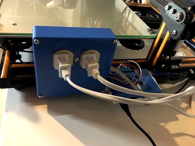
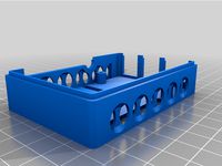
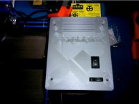
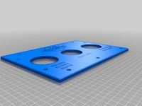
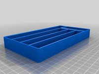
This is a 2-outlet relay-controlled power center that interfaces to a Raspberry Pi running Octoprint. Any 2-wire, 2-outlet receptacle will work for the outlets, for example:
https://www.dkhardware.com/leviton-15-amp-residential-grade-grounding-duplex-outlet-white-r52-05320-00w-product-3141385.html
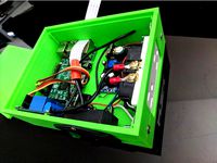
The relay module is:
https://www.amazon.com/SunFounder-Channel-Optocoupler-Expansion-Raspberry/dp/B00E0NTPP4/
Press-fit this module to the mounting bosses and heat stake them with a soldering iron.
This will switch up to 10A per channel at 120VAC.
I'm running OctoPi with the following plug-in to allow GPIO control of the outlets:
https://plugins.octoprint.org/plugins/gpiocontrol/
The relay module connects via F-F jumpers to the RPi's GPIO pins 4 (5V), 6 (GND), 8 (GPIO14), and 10 (GPIO15), but you can select any GPIO pins you want and configure them in OctoPi.
I didn't include a wiring diagram, but it's pretty simple. First, bend the brass ear on the line side of the outlet (brass, "black wire") until it breaks off. This will allow the outlets to be controlled independently. Connect the neutral side of the line cord (wide blade) to the opposite side of the outlet (silver, "white wire"). Connect wires to each of the common connections of the relays and connect both to the line side of the line cord (narrow blade) with a wire nut. Run wires from each of the NO contacts on the relays to the line-side outlet connections.
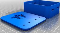
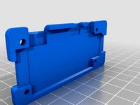
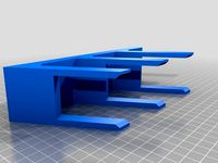
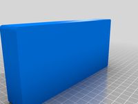
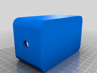
There are two slots on the side of the case. The larger one is for the line cord; the other is for the four GPIO connections. Depending on your line cord (I bought mine from Home Depot), the slot may or may not provide any strain relief. If you're worried about that, knot the conductors before wiring them up.
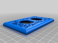
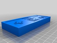
The case mounts to the Creality's 2020 extrusion using two M5X10mm screws and T-nuts. I secured the top to the case with four #4 X 5/8" screws.
THE AUTHOR OF THIS DESIGN ASSUMES NO RESPONSIBILITY FOR INJURY OR DEATH RESULTING FROM BUILDING, ASSEMBLING, OR USING THIS DESIGN. USE CAUTION WHEN WIRING AND TESTING. NEVER WORK ON A POWERED CIRCUIT.
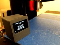
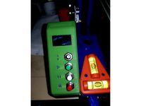
I use this box to remotely control lamps for each of my 3D printers.
UPDATE: I was controlling fluorescent desk lamps with this device, but no more. Switching on a fluorescent light creates enough hash to scramble the RPi and stop the print. I now control LED lamps such as:
https://www.amazon.com/Feit-Electric-CTC40-927CA-FIL/dp/B07YT71BGW/
These cause no problems with electronic interference.
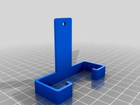
I also created this lamp mounted on the CR10S 2020 extrusion:
https://www.thingiverse.com/thing:4799111
https://www.dkhardware.com/leviton-15-amp-residential-grade-grounding-duplex-outlet-white-r52-05320-00w-product-3141385.html
The relay module is:
https://www.amazon.com/SunFounder-Channel-Optocoupler-Expansion-Raspberry/dp/B00E0NTPP4/
Press-fit this module to the mounting bosses and heat stake them with a soldering iron.
This will switch up to 10A per channel at 120VAC.
I'm running OctoPi with the following plug-in to allow GPIO control of the outlets:
https://plugins.octoprint.org/plugins/gpiocontrol/
The relay module connects via F-F jumpers to the RPi's GPIO pins 4 (5V), 6 (GND), 8 (GPIO14), and 10 (GPIO15), but you can select any GPIO pins you want and configure them in OctoPi.
I didn't include a wiring diagram, but it's pretty simple. First, bend the brass ear on the line side of the outlet (brass, "black wire") until it breaks off. This will allow the outlets to be controlled independently. Connect the neutral side of the line cord (wide blade) to the opposite side of the outlet (silver, "white wire"). Connect wires to each of the common connections of the relays and connect both to the line side of the line cord (narrow blade) with a wire nut. Run wires from each of the NO contacts on the relays to the line-side outlet connections.
There are two slots on the side of the case. The larger one is for the line cord; the other is for the four GPIO connections. Depending on your line cord (I bought mine from Home Depot), the slot may or may not provide any strain relief. If you're worried about that, knot the conductors before wiring them up.
The case mounts to the Creality's 2020 extrusion using two M5X10mm screws and T-nuts. I secured the top to the case with four #4 X 5/8" screws.
THE AUTHOR OF THIS DESIGN ASSUMES NO RESPONSIBILITY FOR INJURY OR DEATH RESULTING FROM BUILDING, ASSEMBLING, OR USING THIS DESIGN. USE CAUTION WHEN WIRING AND TESTING. NEVER WORK ON A POWERED CIRCUIT.
I use this box to remotely control lamps for each of my 3D printers.
UPDATE: I was controlling fluorescent desk lamps with this device, but no more. Switching on a fluorescent light creates enough hash to scramble the RPi and stop the print. I now control LED lamps such as:
https://www.amazon.com/Feit-Electric-CTC40-927CA-FIL/dp/B07YT71BGW/
These cause no problems with electronic interference.
I also created this lamp mounted on the CR10S 2020 extrusion:
https://www.thingiverse.com/thing:4799111
Similar models
thingiverse
free
Raspberry Pi Print Controller Enclosuer by supersaiyen
...7ih6/ref=cm_sw_r_tw_dp_u_x_tmf3abhydrg74
decora outlet - https://www.amazon.com/dp/b000bwi02w/ref=cm_sw_r_tw_dp_u_x_jnf3ab42ardc5
thingiverse
free
Relay Case for two single Relay Units (to be used with Octopi) by Dumbozo
...s using these (e.g. creality ender).
the lid has ventilation gaps in the form of octopi.
if you have any questions, let me know.
thingiverse
free

Raspberry Pi & Electronics Control Case by E_Raw
... gnd) and manage properly:
2x pwn 120mm fans
1x neopixel 60 ledss strip (rgb)
4x relay ports
3x 1-wire ds18b20 temperature probes
thingiverse
free

T junction for PSU to Relay power cord by adjuro
...hing is connected assemble the "cable case " arround the joints.
use m2.5 screws to assemble to 2 halfs ad you are set.
thingiverse
free

4-Channel Relay Module Case by thehair
... of the status led's
the style of the case was based upon this raspberry pi case (http://www.thingiverse.com/thing:922740).
thingiverse
free
Tiny Octoprint Monitor by kirberich
...rinter status, progress of an ongoing job and a minimal status during the night, including a warning if the printer is still hot.
thingiverse
free

Relay Control OctoPrint Wanhao i3 by Jeffeb3
...print can keep on doing whatever it was doing before calling that script, wihtout waiting for the sleep or the command to finish.
thingiverse
free

Ender 3 v2 Octoprint Octopi Case Fan by javiergc
...6 holders because the originals not match with mines and added a hole in the base where the cables from the psu enter in the case
thingiverse
free

Relay Housing for PSU Control
...the ac wires to one side while the control wires are soldered to a pcb and then lead out through a different hole in the housing.
thingiverse
free
Pi Case Upper solid gpio and 16pin cutout by Jason_55904
...nt-enclosure and i am also using a night vision camera with octoprint-octolapse so i added a cutout for the 16 pin ribbon cable.
Charlesodonnell
thingiverse
free

Pen Gift Box by charlesodonnell
...harlesodonnell
thingiverse
a small box for a pen. the pen in the photo is a hand-turned art deco pen from penn state industries.
thingiverse
free

Clip for elastic strap by charlesodonnell
...p for 1/2" elastic strap. the small teeth keep the elastic in place. i used this to repair the dust mask shown in the photo.
thingiverse
free

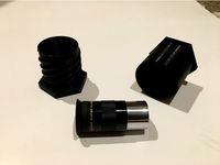
1.25" Telescope Focuser Cover by charlesodonnell
...ingiverse
a simple plug for a 1.25 focuser. the beveled edge makes it easy to insert and the fingerhold makes it easy to remove.
thingiverse
free

4" dust collector hose adapter by charlesodonnell
...4" dust collector hose adapter by charlesodonnell
thingiverse
yet another end adapter for a 4" dust collector hose.
thingiverse
free

Portable DVD Writer Case by charlesodonnell
...he lg model sp80nb80 portable dvd writer. i added two buttons on one side to prevent the eject button from banging into the side.
thingiverse
free

Finder Scope Mount by charlesodonnell
... and a drill guide. this fits an 8" sonotube, id=201.2mm, od=208.7mm. will probably work for other slightly different tubes.
thingiverse
free

Periscope by charlesodonnell
...8: i designed a different, more secure clip for the mirror. see the photo. this will only work with the acrylic mirror specified.
thingiverse
free

Dust port 2-1/4" by charlesodonnell
...
this is a replacement for a broken 2-1/4" dust port from my router table. the photos show the original and the replacement.
thingiverse
free

Mason Jar Fruit Fly Trap by charlesodonnell
... when used with shallow mason jars. i recommend filling the jar with cider vinegar to within 1/4" of the bottom of the trap.
thingiverse
free
Eyepiece Case (Eyepiece Not Included) by charlesodonnell
... accommodate eyepieces ranging from 2-1/2" to 3-1/4" in overall length.
there are no special requirements for printing.
Gpio
thingiverse
free

Pi2 top without gpio by dalefukami
...pi2 top without gpio by dalefukami
thingiverse
removed the gpio access
thingiverse
free

GPIO Male and Female for projects by derek1976
...gpio male and female for projects by derek1976
thingiverse
gpio male and female for projects
thingiverse
free

GPIO 40 Pin Cover by AlexW_579
...r the raspberry pi gpio to stop accidental short circuits.
i am using this on a server where there is no need to access the gpio.
thingiverse
free

Raspberry PI 400 GPIO cover by DakkarDaemor
...raspberry pi 400 gpio cover by dakkardaemor
thingiverse
cover for gpio port on raspberry pi 400.
easy to print
thingiverse
free

Raspberry Pi Zero Case (no GPIO) by charterj
...case (no gpio) by charterj
thingiverse
simple modification of the adafruit pi zero case that removes the gpio cutout on the lid.
thingiverse
free

Raspberry Pi 4 case GPIO by opaque01
...raspberry pi 4 case gpio by opaque01
thingiverse
malolo´s screw-less raspberry pi 4 top case with gpio cutting.
thingiverse
free

Case with GPIO for ODROID C2/C1+ by SuperSonicFlea
...y supersonicflea
thingiverse
this part is a remix of sleeve case for odroid c2/c1+ but it includes an opening for the gpio pins.
thingiverse
free

38pin GPIO holder for Raspberry. by mykail
...maybe a stupid idea but here you go - it mounts your rpi via gpio connector to the frame of your printer. fits vslot. 25% infill.
thingiverse
free

Raspberry Pi GPIO Connector by vexaae
...y) or get a gpio ribbon cable from ebay (expensive but nice).
d) print your own female-to-female gpio connector (cheap and nice).
thingiverse
free
SoaPiBarZero PiStick Top w/o GPIO by tjb1
...barzero pistick top w/o gpio by tjb1
thingiverse
new top for soapibarzero pistick case by markab that has the gpio hole removed.
Octoprint
thingiverse
free

Octoprint Case + Relais by bennylu
...octoprint case + relais by bennylu
thingiverse
octoprint case+ doppel relais
thingiverse
free
Octoprint Control-Panel by sanisam
...von: https://plugins.octoprint.org/plugins/display_panel/?utm_medium=announcements&utm_source=octoprint&utm_content=1.5.2
thingiverse
free

Octoprint Controller by CandlerCustoms
...control. it's super handy.
check out my post about it here: http://www.candlercustoms.com/3d-printed-octoprint-controller/
thingiverse
free

Octoprint Raspberry Pi Logo by ProtomakerSprint
...octoprint raspberry pi logo by protomakersprint
thingiverse
octoprint raspberry pi logo
thingiverse
free

Octoprint plugin - DisplayLayerProgress
...o the plug inhttps://github.com/ollisgit/octoprint-displaylayerprogresshttps://github.com/ollisgit/octoprint-displaylayerprogress
thingiverse
free

OctoPrint Wifi Display by Nori0aw
...it on character lcd screen (20x4).
boards:
esp8266
lcd screen (20x4)
source code: https://github.com/nori0aw/octoprintwifidisplay
thingiverse
free

Octoprint Logo Molle by oiitsame
...octoprint logo molle by oiitsame
thingiverse
thingiverse
free

OctoPrint Statue by KingRahl
...ng octoprint free and available for anyone to use.
a special thanks to janina himmen (@zwergimbikini on twitter) for the design.
thingiverse
free
Case Octoprint (for Raspberry, DC/DC converter and Relay) In file list "Octoprint" is correct! by Genna1986
...ot; is correct! by genna1986
thingiverse
case for raspberry, relay board and dc/dc converter... all you need to use octoprint...
thingiverse
free
Octoprint Ultimaker holder by klenk
...my simple design for attaching my octoprint server to my ultimaker.
raspberry case used: http://www.thingiverse.com/thing:1015706
Outlet
thingiverse
free

OUTLET by umbertocilia
...outlet by umbertocilia
thingiverse
power outlet
thingiverse
free

Outlet Man
...outlet man
thingiverse
outlet man created for the exquisite cyborg project in art 312e.
thingiverse
free
Outlet Cover
...outlet cover
thingiverse
super cool outlet cover, looks great printed using sla
thingiverse
free

Outlet cover by kpkuhl
...outlet cover by kpkuhl
thingiverse
this is an outlet cover that should fit most americal electrical outlets.
thingiverse
free

*outlet hook by imaicom
...*outlet hook by imaicom
thingiverse
outlet hook
thingiverse
free

plate outlet by harrydoordewarry
...plate outlet by harrydoordewarry
thingiverse
outlet plate
thingiverse
free

Plug for electrical outlets.
...plug for electrical outlets.
thingiverse
plug for electrical outlets.
thingiverse
free

Bryant Outlet Cover
...bryant outlet cover
thingiverse
simple 2-gang outlet cover for a bryant nema 14-50 50a outlet.
enjoy!
thingiverse
free

Outlet Cover
...arking that can be felt to mark the presence of an outlet. one can imagine an extension where braille text could be used as well.
thingiverse
free

outlet guard by cfudmh
...outlet guard by cfudmh
thingiverse
outlet guard prevents foriegn objects getting in.
Controlled
thingiverse
free
Megapoints Controllers - Servo Controller by SoBaldrick
...megapoints controllers - servo controller by sobaldrick
thingiverse
megapoints controllers - servo controller base
thingiverse
free

controller by tahmasnx
...controller by tahmasnx
thingiverse
controller fusion 360
thingiverse
free
Control panel
...control panel
thingiverse
control panel for scuba regulator/bank system
thingiverse
free

ph controller
...ph controller
thingiverse
pi zero based reef-pi ph controller
thingiverse
free
NES Controller
...nes controller
thingiverse
this is just a simple nes controller prop. display purposes only.
thingiverse
free

Frame control
...frame control
thingiverse
installation led 12864 reprapdiscount for control machine 3d printer.
thingiverse
free

Control Tower
...control tower
thingiverse
control tower or marshall tower for 1/32 slot car track
thingiverse
free
Controller Hook by P0chapa
... for (maybe) any game controller.
i attached this thing to ps2 controller and third-party xbox controller with double sided tape.
thingiverse
free
Xbox 360 controller stand for 3 controllers by afrolucas
...xbox 360 controller stand for 3 controllers by afrolucas
thingiverse
update for 3 controllers
thingiverse
free

PS4 Controller Stand for 3 Controllers (Dualshock 4)
...the stands for a nvidia shield controller rather than a ps4 controller (so two ps4 controllers and one nvidia shield controller).
Box
thingiverse
free

Box with 'BOX' on it by Mooffyman13
...box with 'box' on it by mooffyman13
thingiverse
a box with 'box' on it
thingiverse
free

Box
...box
thingiverse
this is a box
thingiverse
free
Boxes
...boxes
thingiverse
boxes
thingiverse
free

BOX
...box
thingiverse
box
thingiverse
free

Box in a Box by gbob1959
...ted it. i call it the box in a box.
the small box well not come out of the big box but you can roll the small box around in side.
thingiverse
free

Box
...box
thingiverse
box 1706060mm
thingiverse
free
box
...box
thingiverse
simple box
thingiverse
free

Box
...box
thingiverse
hinged box
thingiverse
free

Box
...box
thingiverse
good box!
thingiverse
free
Box
...box
thingiverse
a box to save things