GrabCAD
gimbal for spot trace GPS tracker
by GrabCAD
Last crawled date: 1 year, 11 months ago
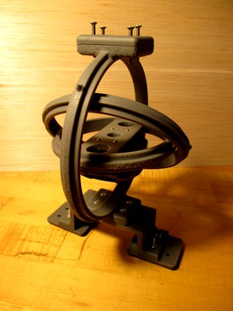
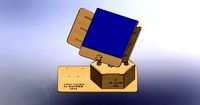
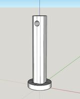
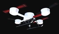
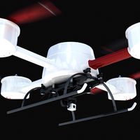
This is a gimbal for a Spot Trace GPS tracker. I made it at NK Labs for a high-altitude balloon launch. It is printed here in SLA Formlabs Grey Resin on a Form 2. There are two versions here. The second was made to reduce weight. It is untested. Some of the photos showing assembly were done in Formlabs Clear Resin.
There are 3 concentric circular frames which can rotate about 2 axes. The hexagonal recess are for M3 nuts. The GPS mount is screwed to the center frame. The GPS is placed in the mount with logo side in. The GPS is kept in the proper orientation by gravity. There is a clamping plate to help you attach to your payload. There is an optional battery frame allowing for tight integration of the battery and gimbal. This allowed for better battery and gimbal positioning for better balance.
Clamping plates are 40mmX50mmX6mm. The clamping plate holes are a loose 3.75mm diameter 15mm x 30mm apart with a 90 degree countersink. The mounting faces (clamps removed) are 156mm apart. The diameter of the outer ring is 152mm.
The weight with GPS installed and screws is about 280 grams without the battery frame.
Battery frame adds 29mm to the height with a 40mmx114mm footprint. Hole spacing is 98mm x 15mm. It can straddle a 71mm x 25mm battery. It adds about 60 grams of mass.
Assemble and use at your own risk. For any launch, look up and follow your local regulations. And give NK Labs a shout out.
BOM
Spot Trace + subscription service (about 91grams without the mount)
From McMaster:
12 - M3 nuts (McMaster-Carr 90591A250)
4 or 8 - M3 screws (flat head, 14mm + clamp attachment width rounded up [you can probably over size by up to 5mm]) (14mm + 1/4in ~=20mm McMaster-Carr 92125A136)
4 - M3 screws (socket cap, 8mm) (McMaster-Carr 91292A112)
4 - nylon spacer, 1/8" long (McMaster-Carr 94639A701) (you can alternatively print the spacers)
6 inches of 1/16in steel rod - (McMaster-Carr 8888K171)
8 - 1/16in push on nuts (McMaster-Carr 94807A015)
super glue (I used Gorilla Super Glue Gel)(optional)
To Print (we used a Form 2 SLA printer with Grey v4 resin, note that support material could double the needed volume of material):
1 inner circle(35mL)
1 middle circle(26mL)
1 outer circle (57mL)
4 spacers (you can alternatively buy the spacers) (0.1mL ea) (I printed extras)
1 or 2 clamp plates (11mL ea)
Optional Battery Frame Accessory:
battery frame (33mL),
+4 M3 nuts,
+1 clamp plate,
4 battery attachment screws (12mm M3 Flathead McMaster-Carr 92125A132)
Tools:
diagonal cutter for hard wire (Knipex 70 01 160)
1/16in drill bit (McMaster-Carr 29115A711)
pin vice (McMaster-Carr 8455A12)
push on tool (McMaster Carr has one ) (I used the hole in the center of dremel collet wrench ) (if I were going to make a lot of these, I could imagine making a jig for a press or pliers wrench)
file/sandpaper
2 mm allen key (for flat head screws) (McMaster-Carr 7813A43)
2.5mm allen keys (for socket cap screws) (McMaster-Carr 7813A44)
Assembly instructions:
1. Inspect and clean up the 3D printed parts. If you printed the spacers, make sure the top and bottom are smooth, flat and parallel.
2. Using the 1/16” drill bit in the pin vice, clean up 1/16” holes by running the 1/16” drill bit through them a few times.
3. Super glue M3 nuts into hexagonal holes being careful not to glue yourself or the threads. 4. Wearing gloves, I like to use a long screw with a nut on the end, add the glue and the pull the nut into the hole so it seats properly. (If I were designing this again, I’d likely move to brass inserts. )
5. Cut 6 in of rod into four - 1.5in sections using diagonal cutters. Roll your sections across a flat surface to inspecting for straightness.
6. Push push-on nut just onto the end of each rod using push-on nut tool (or an appropriate size hole [3.3mm or ⅛” ] in piece of metal) and trim excess (It is a bit tricky. You may want to put something in the way so you don’t push it on too far)
7. Slide the rod with push-on nut through the inner ring, spacer, middle ring.
8. Push on another push-on nut being careful not to squeeze the parts (causing friction). (Maybe use something you can pull out as a spacer)
9. Repeat on the opposite side. Repeat for the outer and middle ring.
10. Screw GPS mount to center ring.
11. Charge GPS and turn it on.
12. Snap in the GPS on mount, logo facing in.
13. Mount completed gimbal to battery base (optional).
14. Mount the assembly onto the payload.
After running with this I made a quick lighter weight version in case we needed to launch again. In the future I think it would be fun FEA exercise to optimize for weight and durability.
Lighter-weight replacement parts:
1 inner circle lighter (13mL)
1 middle circle lighter (22mL)
1 outer circle lighter (25mL)
battery frame lighter (30mL)
This version is a little smaller and mounted from only one side. Without the battery frame, approximately 130mm height clearance is needed. In the other frames 125mm (off center) - 135 (centered)
The weight of the lighter assembly with GPS installed and no battery frame is about 180 grams.
The smaller version is a little trickier to put together. It remains untested.
Similar models
thingiverse
free

Contour GPS Low Profile DYE I5 Camera Mount by AdrianW
...
parts needed:
1/4-20 jamb nut - install in the nut trap inside the mount
m3 screw 25mm long - for clamping
m3 nut - for clamping
thingiverse
free

Gimbal or battery cage mount by gregsky
...y cage to fit a standard 10mm tube at 60mm distance.
all screws and nuts are m3.
the distance between holes on the bottom is 30mm
3dwarehouse
free

spacer, round, aluminum, no. 8 screw, 0.3125 in. OD, 1 in. long, McMaster-Carr 92510A549
...ng, mcmaster-carr 92510a549
3dwarehouse
spacer, round, aluminum, no. 8 screw, 0.3125 in. od, 1 in. long, mcmaster-carr 92510a549
thingiverse
free
LiveStreaming Rig by jbantum
...carr 91400a198
(4) 8-32 nuts - mcmaster carr 90480a009
(4) 1/4-20 bolts - mcmaster carr 91309a541 (secure to 1/4-20 coupler nuts)
thingiverse
free

GoPro Session Gimbal Mount (DYS Gimbal) by Quadropus
...nced correctly. if this mount is used on a different gimbal, results may vary. the mount can be printed without support material.
3dwarehouse
free

nut, 4-40, McMaster-Carr 90257A005
...nut, 4-40, mcmaster-carr 90257a005
3dwarehouse
nut, 4-40, mcmaster-carr 90257a005
thingiverse
free

Feiyu Tech G4 Gimbal Holder with 1/4 inch mount by ramprojects
...with a 1/4 inch mounting. for the holder you need the 3d printed part, a 1/4 inch nut, a hexagon socket screw m3x10 and a nut m3.
3dwarehouse
free
clamp, pipe, mount, 1.25 dia. pipe, McMaster-Carr 9578T67
...clamp, pipe, mount, 1.25 dia. pipe, mcmaster-carr 9578t67
3dwarehouse
clamp, pipe, mount, 1.25 dia. pipe, mcmaster-carr 9578t67
thingiverse
free
DJI Phantom 2 H3-3D Gimbal Spacer by markab
... spacer will prevent the gimbal touching the battery.
you will need to swap out the standard mounting screws for 4 m3x8mm screws.
thingiverse
free

Sony HDR AS20, AS15, etc. No-Gimbal Mount for DJI Phantom 2 by jaln
...ap available elsewhere here on thingyverse.
an alternate plate design can be found here:http://www.thingiverse.com/thing:677486
Tracker
turbosquid
$8

Tracker Knife
... model tracker knife for download as blend, dae, fbx, and obj on turbosquid: 3d models for games, architecture, videos. (1588741)
turbosquid
$1

Tracker Knife
... available on turbo squid, the world's leading provider of digital 3d models for visualization, films, television, and games.
3d_export
$5
solar tracker
...aterial : -arduino uno -2 step motor with driver -4 ldr sensor -some wires -small photovoltaiic pannel -buzzer -cnc laser machine
turbosquid
$23
E3D -HTC Vive Tracker
...model e3d -htc vive tracker for download as max, obj, and c4d on turbosquid: 3d models for games, architecture, videos. (1190728)
3d_export
$7

sci-fi injector or tracker
... can be tracker, use as you want. pbr 4k contain: blend (includes high poly)/ dae / fbx / obj / stl / glowing injector + box
3d_export
$10
Motion Tracker Aliens
...er out moving objects from stationary background and then displayed them on the monitor as a series of contours of probable loci.
3d_export
$5
single axis solar tracker stand
...single axis solar tracker stand
3dexport
3d_export
$60
grumman s-2 f tracker
...ining in service with other air arms into the 21st century. argentina and brazil are the last countries to still use the tracker.
3d_export
$19

Chevrolet tracker 2021
...pport ticket and request for that. we can convert 3d models to: .stl, .c4d, .obj, .fbx, .ma/.mb, .lwo/.lws, .3ds, .3dm, .dxf/.dwg
3d_export
$25
emergency power with solar tracker
...cker
3dexport
this is a tool used to distribute electricity during an emergency disaster, it is recommended to use sketchup 2019
Trace
3ddd
$1

TRACE
...trace
3ddd
itre , trace
design - andrea garuti. 2009 itre
design_connected
$16
Trace 1
...trace 1
designconnected
blu dot trace 1 computer generated 3d model.
3ddd
$1

Chair Desalto Trace
...chair desalto trace
3ddd
desalto , trace
chair desalto trace
design_connected
$16

Trace Chair
...trace chair
designconnected
desalto trace chair armchairs computer generated 3d model. designed by shin azumi.
design_connected
$16

Traced Rug
...traced rug
designconnected
nani marquina traced rug computer generated 3d model. designed by guixé, marti.
design_connected
$16

Trace Carpet
...trace carpet
designconnected
ligne roset trace carpet computer generated 3d model. designed by azambourg , françois.
3ddd
free
Itre / Trace
...itre / trace
3ddd
itre
itre trace pendant lamp and wall lamp. max 2011 x64 and fbx formats included.
turbosquid
$28

TRACE LEATHER CHAIR
...royalty free 3d model trace leather chair for download as max on turbosquid: 3d models for games, architecture, videos. (1522589)
turbosquid
$31

Ring Trace print model
...trace print model for download as max, 3ds, fbx, obj, and stl on turbosquid: 3d models for games, architecture, videos. (1576849)
turbosquid
$3

NaughtOne Trace Table Collection
... available on turbo squid, the world's leading provider of digital 3d models for visualization, films, television, and games.
Gimbal
turbosquid
$1
Yuneec Save Stick for Gimbal
... available on turbo squid, the world's leading provider of digital 3d models for visualization, films, television, and games.
3d_export
$20
splashdrone gimbal camera
...nsions. all textures used have been included. thank you for purchasing this model!! click on my username to see more of my models
3d_export
$40
splashdrone 3 plus with gimbal camera
...nsions. all textures used have been included. thank you for purchasing this model!! click on my username to see more of my models
turbosquid
$88
DJI Phantom 2 Quadcopter with gimbal for GoPro HERO4 or 3
... available on turbo squid, the world's leading provider of digital 3d models for visualization, films, television, and games.
3d_export
$5

concentrate box
...concentrate box 3dexport concealer box with handle and gimbal ...
cg_studio
$55
Drone Quadrocopter With Camera Rigged3d model
...fly wing propeller rc video camera sky dron spy gimbal gopro riged aircraft toy .obj .fbx .max .3ds -...
3d_ocean
$29
Drone Quadrocopter With Camera Rigged
...quadrocopter with camera rigged 3docean aircraft camera dron fly gimbal gopro propeller quadrocopter rc riged sky sport spy toy...
3ddd
free
Foucault's Iron Orb
...physicist léon foucault's gyroscope inspired our openwork globe. its double-gimbal frame is built of iron around a nucleus of...
thingiverse
free
Gimbal by tannermichael
...amera and gravity to self level. the gimbal uses .125" axles to pivot on. this gimbal was made using autodesk inventor 2015.
thingiverse
free

2020 Gimbal
...2020 gimbal
thingiverse
2020 gimbal
Gps
3ddd
free
Подавитель GPS
...подавитель gps
3ddd
подавитель gps
3ddd
free

Подавитель GPS
...подавитель gps
3ddd
подавитель gps
3ddd
free

Cтол GP
...cтол gp
3ddd
обеденный , giorgio piotto
cтол gp
turbosquid
$5
GPS navigation
...e 3d model gps navigation for download as blend, fbx, and obj on turbosquid: 3d models for games, architecture, videos. (1636695)
turbosquid
$4
GP-5
...lty free 3d model gp-5 for download as 3ds, max, obj, and fbx on turbosquid: 3d models for games, architecture, videos. (1160699)
turbosquid
$60
TomTom GPS
... available on turbo squid, the world's leading provider of digital 3d models for visualization, films, television, and games.
turbosquid
free

GPS/TV
... available on turbo squid, the world's leading provider of digital 3d models for visualization, films, television, and games.
3d_export
$5

Battery GP 3D Model
...battery gp 3d model
3dexport
battery gp
battery gp 3d model wasiliy 40319 3dexport
3d_export
$5

gas mask gp-5
...gas mask gp-5
3dexport
gas mask gp-5
cg_studio
$36

Gps device3d model
...ice3d model
cgstudio
.3ds .c4d .dxf .obj - gps device 3d model, royalty free license available, instant download after purchase.
Spot
archibase_planet
free
Spot
...spot
archibase planet
luminaire spot candlelight
spot n070308 - 3d model (*.gsm+*.3ds) for interior 3d visualization.
archibase_planet
free
Spot
...spot
archibase planet
lighting luminaire candlelight
spot - 3d model (*.gsm+*.3ds) for interior 3d visualization.
3d_export
$5

spot chair
...spot chair
3dexport
modern spot chair
3ddd
$1
light Spot
...light spot
3ddd
ecosense spot light
3ddd
$1
Bebop spots
... light , cosmo
подвесной светильник bebop spots. диаметр 450мм.
3ddd
$1
Jumbo Spot
...jumbo spot
3ddd
kare , тренога
jumbo spot
3ddd
$1
davide groppi spot sistema, spot 1
...davide groppi spot sistema, spot 1
3ddd
davide groppi
davide groppi spot sistema, spot 1
corona+vray
turbosquid
$9
Spot
... available on turbo squid, the world's leading provider of digital 3d models for visualization, films, television, and games.
turbosquid
$8
spots
... available on turbo squid, the world's leading provider of digital 3d models for visualization, films, television, and games.
design_connected
$16
Spot Light
...spot light
designconnected
spot light computer generated 3d model.