Thingiverse
GhostG17 by wyogunguru
by Thingiverse
Last crawled date: 2 years, 11 months ago
Re-mixed by WyoGunGuru
Original information and credits
Author
FreeMenDontAskPermission (FreeMenDontAsk)
"F17" Edits done by d33pthought
"VG17" Edits done by nguyenkvvn
Testing & Technical Author
Ivanthetroll (@IvanTheTroll12)
Version
1.1
Description
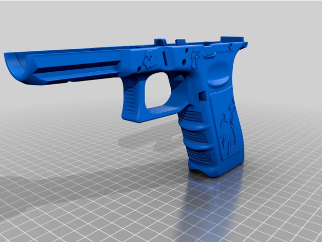
VG17 Update Notes: Building up on FMDA's vision of a base Glock platform being used to make bespoke/custom deriatives, the edits made to d33pthought's update attempt to match the ergonomics found in a Polymer80 frame. Namely speaking, features such as the frame-recessed mag release "extension", picatinny rails vs Glock rails, and the more steeper grip angle that's flatter, compared to the Glock's "curved backstrap". Kept below is the original README from d33pthought's package, and his F17 Update.md document is kept here as well. (Do note, that this package only includes the frame as modified. Other files, such as rails, and spec sheets can be found in d33pthought's original package.)
F17 Update Notes: The F17 update fixes a few issues with the original FMDA G17 model - the mag catch spring fitment, slide latch spring fitment, etc. For a full list of changs, check the F17 Update.md document.
This is the result of several months of experimentation in order to have a base Glock platform that the gun community can design around. This had been done before in .22lr and then I was contacted by FreeMenDontAsk via Twitter where he told me he had a method for making 9mm Glock pistols that worked well. Much of his original work was lost in a computer crash so we recreated his work.
The key to this project is the DIY-friendliness. Given the laws regulating the components of firearms, a Glock frame that is customizable is exactly what FOSSCAD needs.
The system relies on a DIY metal rail system which is added to a printed frame. This results in longevity of use, reliability and safety, all while keeping the costs and complexity to manufacture low.
The use of simple metal parts in combination with printed components holds a lot of potential for the future; FreeMenDontAsk is already working on other handgun models. Even outside of gun making, this could be useful for a wide array of printed projects.
Now, this write-up will be thorough so bear with us. This Readme is broken into four sections:
Tools and Parts List
The Rails - These can be bought from spookyrails.com or riptiderails.com - both sites share the vision and support the devs.
The Frame
Assembly
Troubleshooting
The difficultly level of this build varies with the user. We are good with tools and I’d say this build is not any harder than making an 80% lower for an AR-15. As time goes on the gun community with gain a better understanding for this design.
Note: The included STL files are not high-poly. This should not show up in your prints but some may
notice this in their slicer. If you wish to use high-poly STL files you can export them from the STEP or
F3D files which are included in the parts folder.
Instruction Videos
To aid you in this project and to make this document MUCH shorter, below is a list of instructional videos. These videos are broken into different parts and are designed to show you things that are difficult to express in writing. We reference these videos throughout this document, you should watch the videos carefully before attempting this build so that you understand this tutorial completely.
FreeMan's Glock 17 Assembly Tutorial Playlist:
https://www.youtube.com/playlist?list=PLZzfUB_pwdJ58NWjy10gbhjhukDxxcxUf
FreeMan's Glock 17 Assembly Tutorial Parts 1-3 (Same as above Playlist):
Part 1 - https://gunstreamer.com/watch/U3T4bJjzVALzZdc
Part 2 - https://gunstreamer.com/watch/4rCjJh2MX6gTlLG
Part 3a - https://gunstreamer.com/watch/4HD8mNDIdbbMwQS
Part 3b - https://gunstreamer.com/watch/115JAEQDa87zTBK
Part 3c - https://gunstreamer.com/watch/uBbhEQt7i2CSkOI
1. Tools and Parts List
Below is a list of tools, parts and materials you should need to complete this project.
Materials:
eSun PLA+ or DuPont Zytel filament (or filament of your choice)
Epoxy (if rail block is loose)
Sandpaper
.75"x1" Aluminum bar stock
M2.5 x 8mm screws (M2 screws can be used but M2.5 is recommended)
Tools:
Dremel Tool (Dremel 3000 works well)
Cutting wheels, sanding wheels, polishing wheel and compound
Metal files, including small diameter rat-tailed file
Manual Mill, CNC Mill or X-Y Vise on a Drill Press (to mill the rails)
M2.5 tap + 2.05mm drill bit
Drill (battery, corded, or hand)
Small and medium sized screwdriver
Small punches
Off the shelf Glock parts:
Complete G17 upper (dressed or finished upper, barrel, recoil spring assembly)
Complete G17 lower parts kit (from Midway USA or elsewhere)
G17 3-pin locking block (from Midway USA or elsewhere)
2. The Rails
The specs for the rails are minimum dimensions; aim to overshoot them slightly if you are manually milling them. The dimensions given are for CNC or a milling setup. DO NOT UNDERSHOOT THE GIVEN DIMENSIONS. You can always remove more material if the slide does not fit, it is much harder to material after the fact.
2.1 Material
Aluminum or Mild Steel? I recommend aluminum just because it’s easy to work with. The rails are long enough that the softness of the aluminum isn’t an issue. The surface area lets them last a really long time. I have 700 shots on one rail block, 300 on another, and 900 shots on my rear rails; none have worn
beyond a thousandth of an inch and that is such tight measurement that it could be blamed on caliper reading.
Something like a 3/4" X 1" ALUMINUM 6061 FLAT BAR 12" long .750 Solid Mill Stock from Amazon would works well. I have used cheap Chinese aluminum off of Amazon; 1x.75” bar stock is ideal and leaves a little material to be faced off. I will make a video explaining how to machine the rails at some point. The dimensions are included in the package for people who are knowledgeable, crafty and willing to give it a try.
The front rail can be secured by a cut down drill bit the same size as the pin hole in the block, or you can use a 3mm roll pin that is 28 mm. long. The rear rails work well with high quality M2.5x8mm screws with the ends of the screws ground down to leave them about 7.25 mm. long. The rear rails must be
tapped for M2.5 threads of course, so the holes in them should be drilled with a 2.05 mm. drill bit. Kits are available on Amazon which offer a paired set of the M2.5 tap and 2.05 mm. drill bit.
2.2 Tooling/Sourcing
Ideally, you have or know someone with a mill, a x-y vise and a drill press, or a Ghost Gunner machine. Included with the files will be a printable jig for the Ghost Gunner created by Flood from FOSSCAD (he’s the best!). Hopefully one of the more GG savvy folks can make a tutorial showing how to set that up
on the GG and make it work.
I used a milling machine to make my first two blocks and have made a rough block from the end of a 12” bar stock to profile a rail using a Dremel tool and metal files and a hacksaw. We will include paper templates and a Dremel Jig soon that will aid in making the rails “the 3rd world way”.
Knowing how to read a 2d drawing is very important when making the rails, as is owning and knowing how to use a set of calipers. I’ll include quick 101s in my tutorial on machining the rails.
Eventually I plan on using Lost PLA Casting to make the rails. More on that in the future.
There are multiple parties interested in selling the rails in small batches. We will see how that pans out.
To sum it up, the rails are the hardest part of the build but with the many ways to achieve this it should be possible for anyone who wants to make them.
3. The Frame
Screenshots of my slicer settings are included in the renders folder.
3.1 Print Settings
For a light duty/workable frames:
Material: eSun PLA+
Print Temp: 235 C
Bed Temp: 60 C
Bed Prep: Wipe clean, apply a thick layer of Elmer’s glue stick. Kapton tape is recommended since this frame will really stick to the bed tight if you use the STL with the raft.
Infill: 100%, Rectilinear Fill
Enclosure: None
Orientation: not super critical but using the STL with the raft will result in far less warp. Warp is the enemy of this project.
Supports: full, hexagonal infill, sheathing on infill optional but recommended if your slicer supports it.
Remember that PLA will not stand up to hot environments. While the gun itself won’t hold enough heat to hurt the frame (I dumped 50 rounds as quick as I could load them without issue), having this frame sit in a hot car would damage it.
For a heavy duty/durable frames:
Material: Zytel or Glass filled Zytel
Print Temp: 287 C
Bed Temp: 100 C
Bed Prep: Wipe clean, apply a thick layer of Elmer’s glue stick. Kapton tape is recommended since this frame will really stick to the bed tight if you use the STL with the raft.
Infill: 100%, Rectilinear Fill
Enclosure: None needed, but it will not hurt if you use one.
Orientation: not super critical but using the STL with the raft will result in far less warp. Warp is the enemy of this project.
If you use glass filled Zytel, you will need to coat the outside of the frame with fiberglass resin because the glass fill is very abrasive. Either Zytel frame will stand up to excessive amounts of abuse. Boiling the Zytel frame in water after printing will help layer adhesion without warping the part.
3.2 Finishing the Frame
There are plenty of steps here to complete the build but it might be easier if I just refer you to the instruction videos above. In general, it is the same process as putting a normal Glock together but with the drop-in rails for this version. The only part that really needs hand fitting is the locking block. The locking block needs to be tight, so it may take a bit to get situated correctly. Because each printer will print differently, we did not adjust the CAD to my printer because that may cause issues with other people’s builds. This is explained in the instructional videos above.
4. Assembly
Important items to note for assembly are noted in the instructional videos, but some are important enough to mentioned in this Readme as well:
I advise NOT firing a completed gun at a public range due to the possibility of inadvertently making an unsafe gun. If you leave the rear rails sitting too high, the striker can slip and you will have double or triple wild-fires. Make sure the gun is in good working order by function testing thoroughly (rack the slide hard and ensure that the gun cocks and does not just let the striker fall). Bear in mind that you are making this at your own risk; if you follow the instructions it should not double fire. If you do not follow directions, you might get yourself in trouble. Be safe out
there.
Holes must be drilled to size. Don’t try and hammer the pins in. They should go in easy.
If your front rail block is loose, consider just a little JB weld or epoxy on the sides/front to steady it. A loose front rail can cause issues.
If the locking block pin holes don’t line up, don’t try and force the pins through.
Yes, the rear rails are necessary. Do not fire the gun without them. See what is advised above; we are not guessing.
Check your rail height by pressing down on the barrel when the gun is in battery. It should depress some but should not unlock the action. If the action unlocks, your rails are way too high. I’ll provide footage in the machining video showing how much my barrel depresses.
In general:
Remove all support material
Add front rail section
Add locking block
Add slide lock
Add trigger bar/housing assembly
Remove trigger bar/housing assembly once fitment is verified
Screw in rear rails
Reinstall trigger assembly
Pin in the locking block, trigger assembly, and slide stop
Ensure the rails are flat/on the same plane using a straightedge
Ensure fitment of the slide with barrel and spring removed
Ensure fitment and function of the pistol with barrel and spring installed
Function test! Function test! Function test! Rack that slide real hard.
Troubleshooting
While this project is at the point where it is something I believe is repeatable, I’ll include some of the issues that I ran into which seemed to be the fault of my manufacturing.
Make sure the rail specs are not undershot. The specs on the drawings are minimum values, or values for CNC to achieve. Remember, if you leave dimensions long, you can file it to fit the slide when you are assembling the gun. If you leave it too small, you can cause serious problems including personal injury. Be safe and smart. Glock slides do fit pretty loose, but if your whole slide is rattling on the gun, you did it wrong.
5.1 Dead Triggers or No Reset
This is perhaps the most common issue I ran into. It is caused when the trigger bar does not pop up as it should when the slide recoils. If your right hand rear rail is too wide, it will cause dead triggers. If it is not screwed in such that it fits parallel to the frame, it will cause dead triggers. I ended up dremeling my right rear rail down some on the inside to add some clearance. This may or may not help you. Remember to grind down the screws if they protrude through the rail section at all. I will also point out one spot on the frame that might benefit from a bit of sanding to help fix dead triggers.
5.2 Double Fires
The only time I had double fires is when the trigger housing did not fit tight and the rails were too high. The housing should now fit tight, so if your rails are to spec in terms of height you should not have issues.
5.3 Locking Block will not Line Up
More fitment work is needed for the locking block. Watch that section of the instructional video closely.
5.4 Slide won’t Fit on the Rails
Your rails are either not square enough, or are out of spec. You can use a Dremel or a metal file to hand-profile the rails. My first set of rails needed hand fitting, my second I made exactly to the blueprints and the slide fit with minimal fitting on the rear rails.
5.5 Failure to Extract
I had a phantom FTE issue pop up as I was doing this project. I’m convinced it’s the 80PBuilder parts kit’s fault. My order for a new extractor, firing pin safety and spring from Brownells has been backordered, so I won’t be able to confirm that it’s the upper before release.
Personally I use
E-Sun Pla+ @ .1 resolution slow speed print takes about 2 days with my settings but it's really up to you how you want to do it.
Original information and credits
Author
FreeMenDontAskPermission (FreeMenDontAsk)
"F17" Edits done by d33pthought
"VG17" Edits done by nguyenkvvn
Testing & Technical Author
Ivanthetroll (@IvanTheTroll12)
Version
1.1
Description
VG17 Update Notes: Building up on FMDA's vision of a base Glock platform being used to make bespoke/custom deriatives, the edits made to d33pthought's update attempt to match the ergonomics found in a Polymer80 frame. Namely speaking, features such as the frame-recessed mag release "extension", picatinny rails vs Glock rails, and the more steeper grip angle that's flatter, compared to the Glock's "curved backstrap". Kept below is the original README from d33pthought's package, and his F17 Update.md document is kept here as well. (Do note, that this package only includes the frame as modified. Other files, such as rails, and spec sheets can be found in d33pthought's original package.)
F17 Update Notes: The F17 update fixes a few issues with the original FMDA G17 model - the mag catch spring fitment, slide latch spring fitment, etc. For a full list of changs, check the F17 Update.md document.
This is the result of several months of experimentation in order to have a base Glock platform that the gun community can design around. This had been done before in .22lr and then I was contacted by FreeMenDontAsk via Twitter where he told me he had a method for making 9mm Glock pistols that worked well. Much of his original work was lost in a computer crash so we recreated his work.
The key to this project is the DIY-friendliness. Given the laws regulating the components of firearms, a Glock frame that is customizable is exactly what FOSSCAD needs.
The system relies on a DIY metal rail system which is added to a printed frame. This results in longevity of use, reliability and safety, all while keeping the costs and complexity to manufacture low.
The use of simple metal parts in combination with printed components holds a lot of potential for the future; FreeMenDontAsk is already working on other handgun models. Even outside of gun making, this could be useful for a wide array of printed projects.
Now, this write-up will be thorough so bear with us. This Readme is broken into four sections:
Tools and Parts List
The Rails - These can be bought from spookyrails.com or riptiderails.com - both sites share the vision and support the devs.
The Frame
Assembly
Troubleshooting
The difficultly level of this build varies with the user. We are good with tools and I’d say this build is not any harder than making an 80% lower for an AR-15. As time goes on the gun community with gain a better understanding for this design.
Note: The included STL files are not high-poly. This should not show up in your prints but some may
notice this in their slicer. If you wish to use high-poly STL files you can export them from the STEP or
F3D files which are included in the parts folder.
Instruction Videos
To aid you in this project and to make this document MUCH shorter, below is a list of instructional videos. These videos are broken into different parts and are designed to show you things that are difficult to express in writing. We reference these videos throughout this document, you should watch the videos carefully before attempting this build so that you understand this tutorial completely.
FreeMan's Glock 17 Assembly Tutorial Playlist:
https://www.youtube.com/playlist?list=PLZzfUB_pwdJ58NWjy10gbhjhukDxxcxUf
FreeMan's Glock 17 Assembly Tutorial Parts 1-3 (Same as above Playlist):
Part 1 - https://gunstreamer.com/watch/U3T4bJjzVALzZdc
Part 2 - https://gunstreamer.com/watch/4rCjJh2MX6gTlLG
Part 3a - https://gunstreamer.com/watch/4HD8mNDIdbbMwQS
Part 3b - https://gunstreamer.com/watch/115JAEQDa87zTBK
Part 3c - https://gunstreamer.com/watch/uBbhEQt7i2CSkOI
1. Tools and Parts List
Below is a list of tools, parts and materials you should need to complete this project.
Materials:
eSun PLA+ or DuPont Zytel filament (or filament of your choice)
Epoxy (if rail block is loose)
Sandpaper
.75"x1" Aluminum bar stock
M2.5 x 8mm screws (M2 screws can be used but M2.5 is recommended)
Tools:
Dremel Tool (Dremel 3000 works well)
Cutting wheels, sanding wheels, polishing wheel and compound
Metal files, including small diameter rat-tailed file
Manual Mill, CNC Mill or X-Y Vise on a Drill Press (to mill the rails)
M2.5 tap + 2.05mm drill bit
Drill (battery, corded, or hand)
Small and medium sized screwdriver
Small punches
Off the shelf Glock parts:
Complete G17 upper (dressed or finished upper, barrel, recoil spring assembly)
Complete G17 lower parts kit (from Midway USA or elsewhere)
G17 3-pin locking block (from Midway USA or elsewhere)
2. The Rails
The specs for the rails are minimum dimensions; aim to overshoot them slightly if you are manually milling them. The dimensions given are for CNC or a milling setup. DO NOT UNDERSHOOT THE GIVEN DIMENSIONS. You can always remove more material if the slide does not fit, it is much harder to material after the fact.
2.1 Material
Aluminum or Mild Steel? I recommend aluminum just because it’s easy to work with. The rails are long enough that the softness of the aluminum isn’t an issue. The surface area lets them last a really long time. I have 700 shots on one rail block, 300 on another, and 900 shots on my rear rails; none have worn
beyond a thousandth of an inch and that is such tight measurement that it could be blamed on caliper reading.
Something like a 3/4" X 1" ALUMINUM 6061 FLAT BAR 12" long .750 Solid Mill Stock from Amazon would works well. I have used cheap Chinese aluminum off of Amazon; 1x.75” bar stock is ideal and leaves a little material to be faced off. I will make a video explaining how to machine the rails at some point. The dimensions are included in the package for people who are knowledgeable, crafty and willing to give it a try.
The front rail can be secured by a cut down drill bit the same size as the pin hole in the block, or you can use a 3mm roll pin that is 28 mm. long. The rear rails work well with high quality M2.5x8mm screws with the ends of the screws ground down to leave them about 7.25 mm. long. The rear rails must be
tapped for M2.5 threads of course, so the holes in them should be drilled with a 2.05 mm. drill bit. Kits are available on Amazon which offer a paired set of the M2.5 tap and 2.05 mm. drill bit.
2.2 Tooling/Sourcing
Ideally, you have or know someone with a mill, a x-y vise and a drill press, or a Ghost Gunner machine. Included with the files will be a printable jig for the Ghost Gunner created by Flood from FOSSCAD (he’s the best!). Hopefully one of the more GG savvy folks can make a tutorial showing how to set that up
on the GG and make it work.
I used a milling machine to make my first two blocks and have made a rough block from the end of a 12” bar stock to profile a rail using a Dremel tool and metal files and a hacksaw. We will include paper templates and a Dremel Jig soon that will aid in making the rails “the 3rd world way”.
Knowing how to read a 2d drawing is very important when making the rails, as is owning and knowing how to use a set of calipers. I’ll include quick 101s in my tutorial on machining the rails.
Eventually I plan on using Lost PLA Casting to make the rails. More on that in the future.
There are multiple parties interested in selling the rails in small batches. We will see how that pans out.
To sum it up, the rails are the hardest part of the build but with the many ways to achieve this it should be possible for anyone who wants to make them.
3. The Frame
Screenshots of my slicer settings are included in the renders folder.
3.1 Print Settings
For a light duty/workable frames:
Material: eSun PLA+
Print Temp: 235 C
Bed Temp: 60 C
Bed Prep: Wipe clean, apply a thick layer of Elmer’s glue stick. Kapton tape is recommended since this frame will really stick to the bed tight if you use the STL with the raft.
Infill: 100%, Rectilinear Fill
Enclosure: None
Orientation: not super critical but using the STL with the raft will result in far less warp. Warp is the enemy of this project.
Supports: full, hexagonal infill, sheathing on infill optional but recommended if your slicer supports it.
Remember that PLA will not stand up to hot environments. While the gun itself won’t hold enough heat to hurt the frame (I dumped 50 rounds as quick as I could load them without issue), having this frame sit in a hot car would damage it.
For a heavy duty/durable frames:
Material: Zytel or Glass filled Zytel
Print Temp: 287 C
Bed Temp: 100 C
Bed Prep: Wipe clean, apply a thick layer of Elmer’s glue stick. Kapton tape is recommended since this frame will really stick to the bed tight if you use the STL with the raft.
Infill: 100%, Rectilinear Fill
Enclosure: None needed, but it will not hurt if you use one.
Orientation: not super critical but using the STL with the raft will result in far less warp. Warp is the enemy of this project.
If you use glass filled Zytel, you will need to coat the outside of the frame with fiberglass resin because the glass fill is very abrasive. Either Zytel frame will stand up to excessive amounts of abuse. Boiling the Zytel frame in water after printing will help layer adhesion without warping the part.
3.2 Finishing the Frame
There are plenty of steps here to complete the build but it might be easier if I just refer you to the instruction videos above. In general, it is the same process as putting a normal Glock together but with the drop-in rails for this version. The only part that really needs hand fitting is the locking block. The locking block needs to be tight, so it may take a bit to get situated correctly. Because each printer will print differently, we did not adjust the CAD to my printer because that may cause issues with other people’s builds. This is explained in the instructional videos above.
4. Assembly
Important items to note for assembly are noted in the instructional videos, but some are important enough to mentioned in this Readme as well:
I advise NOT firing a completed gun at a public range due to the possibility of inadvertently making an unsafe gun. If you leave the rear rails sitting too high, the striker can slip and you will have double or triple wild-fires. Make sure the gun is in good working order by function testing thoroughly (rack the slide hard and ensure that the gun cocks and does not just let the striker fall). Bear in mind that you are making this at your own risk; if you follow the instructions it should not double fire. If you do not follow directions, you might get yourself in trouble. Be safe out
there.
Holes must be drilled to size. Don’t try and hammer the pins in. They should go in easy.
If your front rail block is loose, consider just a little JB weld or epoxy on the sides/front to steady it. A loose front rail can cause issues.
If the locking block pin holes don’t line up, don’t try and force the pins through.
Yes, the rear rails are necessary. Do not fire the gun without them. See what is advised above; we are not guessing.
Check your rail height by pressing down on the barrel when the gun is in battery. It should depress some but should not unlock the action. If the action unlocks, your rails are way too high. I’ll provide footage in the machining video showing how much my barrel depresses.
In general:
Remove all support material
Add front rail section
Add locking block
Add slide lock
Add trigger bar/housing assembly
Remove trigger bar/housing assembly once fitment is verified
Screw in rear rails
Reinstall trigger assembly
Pin in the locking block, trigger assembly, and slide stop
Ensure the rails are flat/on the same plane using a straightedge
Ensure fitment of the slide with barrel and spring removed
Ensure fitment and function of the pistol with barrel and spring installed
Function test! Function test! Function test! Rack that slide real hard.
Troubleshooting
While this project is at the point where it is something I believe is repeatable, I’ll include some of the issues that I ran into which seemed to be the fault of my manufacturing.
Make sure the rail specs are not undershot. The specs on the drawings are minimum values, or values for CNC to achieve. Remember, if you leave dimensions long, you can file it to fit the slide when you are assembling the gun. If you leave it too small, you can cause serious problems including personal injury. Be safe and smart. Glock slides do fit pretty loose, but if your whole slide is rattling on the gun, you did it wrong.
5.1 Dead Triggers or No Reset
This is perhaps the most common issue I ran into. It is caused when the trigger bar does not pop up as it should when the slide recoils. If your right hand rear rail is too wide, it will cause dead triggers. If it is not screwed in such that it fits parallel to the frame, it will cause dead triggers. I ended up dremeling my right rear rail down some on the inside to add some clearance. This may or may not help you. Remember to grind down the screws if they protrude through the rail section at all. I will also point out one spot on the frame that might benefit from a bit of sanding to help fix dead triggers.
5.2 Double Fires
The only time I had double fires is when the trigger housing did not fit tight and the rails were too high. The housing should now fit tight, so if your rails are to spec in terms of height you should not have issues.
5.3 Locking Block will not Line Up
More fitment work is needed for the locking block. Watch that section of the instructional video closely.
5.4 Slide won’t Fit on the Rails
Your rails are either not square enough, or are out of spec. You can use a Dremel or a metal file to hand-profile the rails. My first set of rails needed hand fitting, my second I made exactly to the blueprints and the slide fit with minimal fitting on the rear rails.
5.5 Failure to Extract
I had a phantom FTE issue pop up as I was doing this project. I’m convinced it’s the 80PBuilder parts kit’s fault. My order for a new extractor, firing pin safety and spring from Brownells has been backordered, so I won’t be able to confirm that it’s the upper before release.
Personally I use
E-Sun Pla+ @ .1 resolution slow speed print takes about 2 days with my settings but it's really up to you how you want to do it.
Similar models
thingiverse
free

Drop-Leg Glock Holster by EYYE
...aps securing it on a leg and a belt. it also has a variable screw holes so you can set the angle of a gun. this is pretty handy.
thingiverse
free
glock 17 stock or buffertube or arm brace adapter by adas1223
...ail. fit a pin on the grip as with all glock stocks should have.
added a rail to the rear so a tube or accessories can slide on.
thingiverse
free

Polymer 80 Glock Block by Anonymous_Nobody
...) frame has a steeper angle on the front of the trigger guard as well as an extra hole and the slide release being moved forward.
thingiverse
free
Rubber Band Gun by 22wongdesmond
...t of said trigger. to use the toy, a rubber band should be placed on the uppermost tooth of the gear before pressing the trigger.
cults
free

Handgun Tri-Rail Mount
...pons you use these prints on :)
this thing was made with tinkercad. edit it online https://www.tinkercad.com/things/ia8sydhx2tq
thingiverse
free

80% AR15 lower jig by Hyudryu
...ttom is used as a template to drill out the trigger hole. mark it with a sharpie, and use a drill bit + file to get the job done.
thingiverse
free

Dremel deburring adapter by CrackBaron
...l i used a 3 mm hard metal milling cuter for metal.
the dremel attachment by "karlosek" inspired me to make this thing.
thingiverse
free

Nerf Doublestrike Trigger mod by LeftBrainCo
... take aprt the inside of the gun. if you can get a picture of it's correct position, as i guessed as to where it should lay.
thingiverse
free

Gen 1-4 Glock Flat Face Trigger Shoe by kromehawk
... assembling this part:
1/16" punch
hammer
wire snips for the spring from the pen
320 and/or 800 grit sand paper
exacto knife
thingiverse
free

Wiimote Gun with captive pen spring trigger assembly by madmodder123
...der, especially the trigger area.
i just used a barrel sanding attachment on my dremel and then cleaned it up with a sharp knife.