Thingiverse
GeitPrinter by geit_de
by Thingiverse
Last crawled date: 3 years ago
The GeitPrinter Project
First: Thanks for all the feedback. I do my very best to handle your messages in time.
Second: My name "geit" is spoken "guide", so the printers name actually is "guideprinter". I often hear my name said wrong in streams, so just that for info. :D
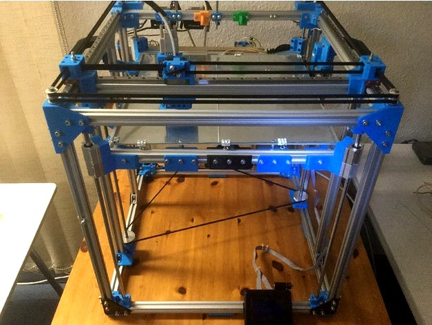
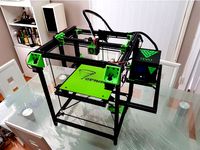
This is a "small" and simple attempt to build a 3d printer. Small and simple are the keywords here. Just some basic parts to print, standard components you can get anywhere and no special and expensive tools required, as I don´t have access to a fancy workshop. Since my workshop skills are next to non existing anyway, everyone should be able to build this printer. :D
The goal was to create a printer using 500mm 2020 extrusions and to use linear rails for the axes. To minimize the impact on the build volume I tried to minimize the components used within the frame. I also wanted to mount the Nema17 motors only behind the printer, where I plan to store have all the electronics, so when later on an enclosure will be added, the electronics will reside outside of the heat chamber and can even be cooled properly. 4 additional 540mm 2020 extrusions are used for the vertical edges to cover the corners.
The rails are 450mm size. The left out 50mm are divided by two and used on the inside of each frame to place the corner brackets.
A very important task for me was to ensure the Y rails are on the same level as the X-rail, which implies that the X beam must be on the same level as the outer frame of the printer. This resulted in a quite strange shape of the XYCarriage (aka. xy joiner), but it turned out to be possible and works very well. The main reason was the tool changing and parking system I had in mind.
As another self set limitation of my design I wanted the XY pulley and the XY joiner section to only use one axle, which in the result causes the timing belts to get quite narrow towards the XY joiner. On the Nema17 block this wasn´t a big issue. As I did not want to mount the Nema17 steppers as overhang to the sides, but at the back, I needed to design a 90° belt angle and an additional pulley to get the belt around.
The desired build volume will probably be 395mm x 335mm x 430mm. This is due to several things that cannot be changed easily. Like the linear rail block and the hotend dimensions eat alot of space. Due to the corner brackets I already lost 50mm on each axis, since the linear rail block would collide. I probably could get rid of them and use longer rails, but at the cost of stability. That is also one reason I did not use 400mm or even 300mm extrusions as a starting point as the result should be far bigger then the build volume of my AnetA8.
The tool changer mechanism eats additional 50mm of the Y-axis anyway. That is the reason why we get around only about 335mm in reachable size there. As a bonus I will be able to park four (!!) tool heads. Not counting modules that can be easy stored externally like a laser engraver.
Tool changing is more or less impossible with a preset system like the Anet A8 or my TronXY X5. It is also far easier to modify and fix things on a big printer compared to fiddling around on some small one. Even simple experiments are impossible due size limits. Especially the TronXY X5 (the one with real rods and not the junky plastic wheel edition) is by default so packed that it is hard to even get the hands in to add fixation clamps for the glass surface.
The GeitPrinter is using a dual lead screw driven z axis. Two 60 teeth driver pulleys create enough torque to lift about 4.7Kg additional weight with a single Nema17 stepper.
At least the crappy prototype parts did manage that. Also keep in mind the aluminium bed and the 2020 extrusions used for the bed are not included in this calculation, so the total amount of weight the construction was already able to lift was around 7Kg in total.
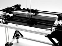
The bed frame has three mount points with very nice bed level adjustment wheels. These work great. The 300x300 heat bed is currently not mounted, as I want to finish the electronics casing first, to avoid messing around with mains power and low voltage loosely mixed together and risking to break something or someone.
I also got new longer ribbon cables for the display. Now I am able to move and mount the Ramps board behind the printer as planed.
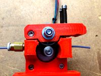
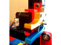
I currently mounted only two extruders. They came with corner brackets and I needed to enlarge the slot holes from M4 to M5, to make it fit (M5 T-Nuts). I could have printed the part, but in my experience extruder motors gets quite hot and the heat must be transferred away from the filament, which a metal frame is perfect for. I had much trouble with my Bowden Anet in this department and only an additional fan on the extruder helped to fix filament jams. Since the ANet extruder is basically PLA mounted on Acryl, there is no other way to transfer the head away from the Nema17. I hope the metal bracket, as well as the printer frame, will act like a huge heat sink. Since the Nema17s are getting quiet hot in general I also have one part less to reprint in ABS when the design has been finalized.
The first prototype version of my printer used optical end stops for the X and y axis. It worked fine, but in the end the moving wires from the x carriage around the printer to the electronic was a real show stopper. So I adapted my design and replaced the old stepper drivers. The new TMC2209 drivers allow sensor less homing without any additional wiring needed.
This works surprisingly well. The only end stop left is for the z axis as we don't want to crash into our tools when homing.
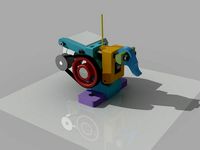
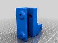
The new X-Carriage with belt tensioner and a magnetic tool holder is working like a charm. This way the printer can swap the tools on demand. And guess what? It works perfect. I used three 10mm neodymium magnet balls on the holder and M6 washers on the tool mounts. There is no active component and no additional wiring. Many thanks to Frank Herrmann for inventing this mechanism in the first place. Check out his YouTube profile for additional information, but be aware that both systems only share the basic mechanism and not the actual measurements.
The tool mount is basically a bracket which the tool gets mounted on. Hence the naming. :D I designed a fully enclosed E3DV6 mount, with two separate air flow channels for part and heat break cooling. A third channel guides the wires from the hot end to a Sub-D9 connector, so the tool block can be removed by simply unplugging the Sub-D cable and the PTFE-Tube. This will make replacing and cleaning tools so much easier.
Here the basic design in action:
https://youtu.be/fZJShQEbW1U
The most recent addition to the printer was the ATX power supply mount, which I modified, so it can be controlled by the Raspberry Pis gpio using OctoPrint. The Pi itself now gets powered by the 5V standby, so for the first time the GeitPrinter is portable and save again, as there are no open high voltage lines and no loose components below the Z axis belt, which is a nice progress. And only one power supply for printer and pi.
Now we have 2020 an the GeitPrinter is still not finished. Well, we are close. I did most of the software fixes. ToolChange is now build in and the Sensorless Homing is 100% accurate.
One thing I noticed missing were the antennas. Well, they are not really antennas, but sticks that got straight up between the extruders and prevent the cables from getting tangled during tool changing. I know. They cannot really tangle, but there weight make them tilt sideways and two extruder cables may laying ontop of each other. The Zip-tie or plastic wrap around the cables my cause them to interlock, which is a bad thing, when the print head drives away with the extruder and the wire is somehow attached to the other wire by interlocking.
This simple antenna like solution is fixing this odd behaviour and also gives the printer proper height dimensions, so nothing can accidentally rip of cables while parked.
30.Jul-2020
Added reworked lead screw mount with integrated z adjustment knob.
04.Aug-2020
Added Nema17 mount bracket.
09.Aug-2020
Marlin firmware containing all changes required to get the GeitPrinter up and running
is available here: https://github.com/Geitde/Marlin/tree/bugfix-2.0.x
TODO
print with more than one tool head :)
finishing parts (3rd extruder, 3rd SSR)
WARNING:
The printer is currently under heavy construction and many things aren´t solved yet, but I am hopefully getting there. I am a completely Beginner with CAD in general and FreeCAD in specific. I am getting better and faster designing things, but I am sure I made a lot of mistakes people notice right away. So if you have any tips or comments feel free to leave a note.
The included files are not ment to be used yet. I just added them for documentation purposes and they will update frequently. When I finished my design I will include the FreeCAD source files.
When left/right/front/back is used in naming of the parts, the direction is to be seen from the front of the printer and not from the side the part gets mounted on.
ADDITIONAL NOTES:
The big butterfly shaped thing on the printers front is an ipad holder. I want to mount an old ipad1 to have something at hand dealing with OctoPrint, when working on the printer while having my hands free.
Of course this may look like overkill as there is the LCD Controller right next to it, but sometimes the ipad is more handy and you can easily take it off, when working on the side. Especially when re/starting a print via OctoPrint you need additional help. I also have a spare ipad1 which is perfect for the job. While assembling I used the empty mount as "this is the front" indicator. It will probably be mounted above the LCD display anyway.
The ipad Idea probably killed itself as I am not able to log into OctoPrint with the old ipad anymore. That´s a bummer. :(
The display mount: https://www.thingiverse.com/thing:1975439
The display case: https://www.thingiverse.com/thing:213852
Case handles: https://www.thingiverse.com/thing:754938
Here the original magnetic tool changer my design is based on. The XHTC was designed by Frank Herrmann (xpix): https://www.thingiverse.com/thing:3036622 Please note that the original XHTC and the GeitPrinter only share the basic docking mechanism and not the measurements. The systems are not compatible to each other as my printer is intended to have the x axis (2020 beam) on the same level as the y axis.
PARTS TO PRINT:
Each section following here can be fully assembled without the need of the following parts. Just make sure you print the sections in the order of this list, as you cannot mount any axis without the base cube and so on.
Base Cube:
4x ZRodMountBottom.obj (top and bottom inner cube)
4x ZRodMountTop.obj (top and bottom inner cube)
2x XYCornerBumperLeft.obj (top front outer cube)
2x XYCornerBumperRight.obj (top front outer cube)
1x NemaMountLeft.obj (top back outer cube)
1x NemaMountRight.obj (top back outer cube)
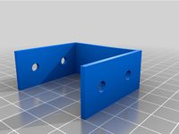
6x FrameCornerCoverBracket.obj (Optional, bottom corners)
4x AdjustableFootCornerBracket.obj (Optional)
4x AdjustableFootLinearBracket.obj (Optional)
Z Axis:
2x ZMountBottom.obj
2x ZMountBed.obj
1x ZMountTop.obj
1x ZMountTop_NoEndStop.obj
1x ZNemaMount.obj
1x ZAdjustBracket.obj
1x ZAdjustKnob.obj
2x FrameTJointCoverBracket.obj (Optional)
XY Axis:
2x XYCarriage.obj
1x MagneticHolder.obj
Bed:
3x BedAdjustMount.obj
3x BedAdjustKnob.obj
4x ZRodMountBed.obj
1x ZBedTConnectionMount.obj
1x ZBedTConnectionMountSmall.obj
Electronics Board:
2x ElectronicsPlate2020Mount.obj
4x ElectronicsPlate2020Spacer.obj
E3DV6 Tool (multiply with the number of tools you want):
1x Separator_V??.obj
1x ToolHolder_V??.obj
1x ToolHolder_E3EV6_V??.obj
1x ToolHolder_E3DV6_Top_V??.obj
Extruder Antenna: (optional, extruder - 1 times)
1x AntennaMount.obj
1x AntennaProtector.obj
PARTLIST:
This list is probably incomplete and just reflects the parts I currently use or will need for sure.
If you want to shrink/increase your build, just a few values need to be tweaked. Lets say you want 100mm less build volume, subtract 100mm from extrusion length and from the linear rail length. Recalculate the timing belt by multiplying the new extrusion length with five. For the print bed y size you need to change the three equal extrusions and for the x axis the two smaller ones.
I designed the basic bed frame to be longer in y direction, so it can be adjusted on its mounts to fit future needs.
If you want it square just adapt the extrusions. Just a small note: The printbed, unlike the 2020 cube, is mounted without corner pieces, so the 440mm extrusions create a 480mm bed frame length in y direction.
Now the parts to print. I suggest you use the following order to build the printer, so you can start while parts are still printing.
General Parts:
1x SKR Pro V1.1
5x TMC2209 stepper drivers
1x LCD display 12864 (may be replaced by a touch screen)
2x 10 pin 1.3m ribbon cables (display,80mm-100mm should work, too)
5x Nema17 (x,y,z,e1,e2, or optional more for additional extruders)
3x 450mm MGN12h linear rail (x carriage, 2x y axis)
2x 450mm 8mm lead screw (z axis lead screw)
2x 8mm lead screw nut (z axis lead screw)
4x 8mm/22 bearing (z lead screw, 608, skate board bearing)
4x 480mm 8mm rod (z axis guide)
8x 8mm linear bearing block LM8UU (z axis guide)
12x 500mm Type6 aluminium extrusion (cubic frame)
4x 540mm Type6 aluminium extrusion (cubic frame)
3x 420mm Type6 aluminium extrusion (print bed frame/electronics mount)
3x 440mm Type6 aluminium extrusion (print bed frame)
1x 485mm Type6 aluminium extrusion (x axis)
2x 2500mm timing belt. (main extrusion length times five)
13x 20mm extrusion corner brackets
1x 400x350x10mm wooden plate (can be metal, too)
2x GT2 driver pulley 60 teeth 8mm bore (with 2 set screws each)
3x GT2 driver pulley 20 teeth 5mm bore (with 2 set screws each)
8x GT2 idle pulley 20 teeth 5mm bore
5x GT2 idle pulley 20 teeth 5mm bore toothless
250x M5 Type 6 pre mount nut (trust me you will need them all)
250x M5x10mm button head hex socket screw
50x M5 Type 6 post mount nut (you will forget something and need these)
50x M3 Type 6 pre mount nut (linear rail mount)
50x M3x10mm screw (linear rail mount)
8x M3x12mm screw (lead screw guide)
8x M3 nut (lead screw guide)
6x M5x80mm screw (2*xy corner, 4*Nema17 axles)
3x M5x35mm countersunk screw (2*xy joiner axles, z fastener Nema17)
12x M5 nut (8x nema axle mount, 4 corner axle mount)
6x M5 nut (self locking, optional)
250x M5 washer (pulley spacing, axle, frame mount screws)
20x M3 8mm countersunk screw (nema17/rail mount)
20x M3 washer
8x M4 10 screw (z rod mount)
8x M4 nut (z rod mount)
1x Optical end stop
1x M6x50mm (z-adjust bracket)
2x M6 Nut (z-adjust mount, z-adjust knob)
2x M2x10mm (z-adjust optical end stop mount)
1x 420mm Rod with 6mm diameter. (Antenna) Metal, wood or plastic (extruders minus one times).
Bedleveling:
3x M4x50mm countersunk screw
3x Spring 20mm length. 7.5mm outer diameter,4-5mm inner diameter
6x M4 washer
3x M4 nut (self locking)
3x M4 nut
For the magnetic tool holder you need:
2x 2,0mmx16mm steel nail
3x 10mm diameter ball shaped neodymium magnets
For each tool head you need:
1x E3DV6 with 30mm fan
1x Blower Fan
1x Sub-D 9 connector male
1x Sub-D 9 connector female
3x M6 Washer
3x M3 12mm screw (base)
1x M3 30mm screw (base)
1x M3 25mm screw (blower)
5x M3 nut (base, blower)
1x M4 20mm (blower)
1x M4 nut (blower)
1x M4 washer (blower)
2x M2 10mm enclosure screws (magnetic parking)
2x M3 15mm counter sunk enclosure screws (E3DV6 fan)
8x 4mm cubic neodymium magnets (magnetic parking)
First: Thanks for all the feedback. I do my very best to handle your messages in time.
Second: My name "geit" is spoken "guide", so the printers name actually is "guideprinter". I often hear my name said wrong in streams, so just that for info. :D
This is a "small" and simple attempt to build a 3d printer. Small and simple are the keywords here. Just some basic parts to print, standard components you can get anywhere and no special and expensive tools required, as I don´t have access to a fancy workshop. Since my workshop skills are next to non existing anyway, everyone should be able to build this printer. :D
The goal was to create a printer using 500mm 2020 extrusions and to use linear rails for the axes. To minimize the impact on the build volume I tried to minimize the components used within the frame. I also wanted to mount the Nema17 motors only behind the printer, where I plan to store have all the electronics, so when later on an enclosure will be added, the electronics will reside outside of the heat chamber and can even be cooled properly. 4 additional 540mm 2020 extrusions are used for the vertical edges to cover the corners.
The rails are 450mm size. The left out 50mm are divided by two and used on the inside of each frame to place the corner brackets.
A very important task for me was to ensure the Y rails are on the same level as the X-rail, which implies that the X beam must be on the same level as the outer frame of the printer. This resulted in a quite strange shape of the XYCarriage (aka. xy joiner), but it turned out to be possible and works very well. The main reason was the tool changing and parking system I had in mind.
As another self set limitation of my design I wanted the XY pulley and the XY joiner section to only use one axle, which in the result causes the timing belts to get quite narrow towards the XY joiner. On the Nema17 block this wasn´t a big issue. As I did not want to mount the Nema17 steppers as overhang to the sides, but at the back, I needed to design a 90° belt angle and an additional pulley to get the belt around.
The desired build volume will probably be 395mm x 335mm x 430mm. This is due to several things that cannot be changed easily. Like the linear rail block and the hotend dimensions eat alot of space. Due to the corner brackets I already lost 50mm on each axis, since the linear rail block would collide. I probably could get rid of them and use longer rails, but at the cost of stability. That is also one reason I did not use 400mm or even 300mm extrusions as a starting point as the result should be far bigger then the build volume of my AnetA8.
The tool changer mechanism eats additional 50mm of the Y-axis anyway. That is the reason why we get around only about 335mm in reachable size there. As a bonus I will be able to park four (!!) tool heads. Not counting modules that can be easy stored externally like a laser engraver.
Tool changing is more or less impossible with a preset system like the Anet A8 or my TronXY X5. It is also far easier to modify and fix things on a big printer compared to fiddling around on some small one. Even simple experiments are impossible due size limits. Especially the TronXY X5 (the one with real rods and not the junky plastic wheel edition) is by default so packed that it is hard to even get the hands in to add fixation clamps for the glass surface.
The GeitPrinter is using a dual lead screw driven z axis. Two 60 teeth driver pulleys create enough torque to lift about 4.7Kg additional weight with a single Nema17 stepper.
At least the crappy prototype parts did manage that. Also keep in mind the aluminium bed and the 2020 extrusions used for the bed are not included in this calculation, so the total amount of weight the construction was already able to lift was around 7Kg in total.
The bed frame has three mount points with very nice bed level adjustment wheels. These work great. The 300x300 heat bed is currently not mounted, as I want to finish the electronics casing first, to avoid messing around with mains power and low voltage loosely mixed together and risking to break something or someone.
I also got new longer ribbon cables for the display. Now I am able to move and mount the Ramps board behind the printer as planed.
I currently mounted only two extruders. They came with corner brackets and I needed to enlarge the slot holes from M4 to M5, to make it fit (M5 T-Nuts). I could have printed the part, but in my experience extruder motors gets quite hot and the heat must be transferred away from the filament, which a metal frame is perfect for. I had much trouble with my Bowden Anet in this department and only an additional fan on the extruder helped to fix filament jams. Since the ANet extruder is basically PLA mounted on Acryl, there is no other way to transfer the head away from the Nema17. I hope the metal bracket, as well as the printer frame, will act like a huge heat sink. Since the Nema17s are getting quiet hot in general I also have one part less to reprint in ABS when the design has been finalized.
The first prototype version of my printer used optical end stops for the X and y axis. It worked fine, but in the end the moving wires from the x carriage around the printer to the electronic was a real show stopper. So I adapted my design and replaced the old stepper drivers. The new TMC2209 drivers allow sensor less homing without any additional wiring needed.
This works surprisingly well. The only end stop left is for the z axis as we don't want to crash into our tools when homing.
The new X-Carriage with belt tensioner and a magnetic tool holder is working like a charm. This way the printer can swap the tools on demand. And guess what? It works perfect. I used three 10mm neodymium magnet balls on the holder and M6 washers on the tool mounts. There is no active component and no additional wiring. Many thanks to Frank Herrmann for inventing this mechanism in the first place. Check out his YouTube profile for additional information, but be aware that both systems only share the basic mechanism and not the actual measurements.
The tool mount is basically a bracket which the tool gets mounted on. Hence the naming. :D I designed a fully enclosed E3DV6 mount, with two separate air flow channels for part and heat break cooling. A third channel guides the wires from the hot end to a Sub-D9 connector, so the tool block can be removed by simply unplugging the Sub-D cable and the PTFE-Tube. This will make replacing and cleaning tools so much easier.
Here the basic design in action:
https://youtu.be/fZJShQEbW1U
The most recent addition to the printer was the ATX power supply mount, which I modified, so it can be controlled by the Raspberry Pis gpio using OctoPrint. The Pi itself now gets powered by the 5V standby, so for the first time the GeitPrinter is portable and save again, as there are no open high voltage lines and no loose components below the Z axis belt, which is a nice progress. And only one power supply for printer and pi.
Now we have 2020 an the GeitPrinter is still not finished. Well, we are close. I did most of the software fixes. ToolChange is now build in and the Sensorless Homing is 100% accurate.
One thing I noticed missing were the antennas. Well, they are not really antennas, but sticks that got straight up between the extruders and prevent the cables from getting tangled during tool changing. I know. They cannot really tangle, but there weight make them tilt sideways and two extruder cables may laying ontop of each other. The Zip-tie or plastic wrap around the cables my cause them to interlock, which is a bad thing, when the print head drives away with the extruder and the wire is somehow attached to the other wire by interlocking.
This simple antenna like solution is fixing this odd behaviour and also gives the printer proper height dimensions, so nothing can accidentally rip of cables while parked.
30.Jul-2020
Added reworked lead screw mount with integrated z adjustment knob.
04.Aug-2020
Added Nema17 mount bracket.
09.Aug-2020
Marlin firmware containing all changes required to get the GeitPrinter up and running
is available here: https://github.com/Geitde/Marlin/tree/bugfix-2.0.x
TODO
print with more than one tool head :)
finishing parts (3rd extruder, 3rd SSR)
WARNING:
The printer is currently under heavy construction and many things aren´t solved yet, but I am hopefully getting there. I am a completely Beginner with CAD in general and FreeCAD in specific. I am getting better and faster designing things, but I am sure I made a lot of mistakes people notice right away. So if you have any tips or comments feel free to leave a note.
The included files are not ment to be used yet. I just added them for documentation purposes and they will update frequently. When I finished my design I will include the FreeCAD source files.
When left/right/front/back is used in naming of the parts, the direction is to be seen from the front of the printer and not from the side the part gets mounted on.
ADDITIONAL NOTES:
The big butterfly shaped thing on the printers front is an ipad holder. I want to mount an old ipad1 to have something at hand dealing with OctoPrint, when working on the printer while having my hands free.
Of course this may look like overkill as there is the LCD Controller right next to it, but sometimes the ipad is more handy and you can easily take it off, when working on the side. Especially when re/starting a print via OctoPrint you need additional help. I also have a spare ipad1 which is perfect for the job. While assembling I used the empty mount as "this is the front" indicator. It will probably be mounted above the LCD display anyway.
The ipad Idea probably killed itself as I am not able to log into OctoPrint with the old ipad anymore. That´s a bummer. :(
The display mount: https://www.thingiverse.com/thing:1975439
The display case: https://www.thingiverse.com/thing:213852
Case handles: https://www.thingiverse.com/thing:754938
Here the original magnetic tool changer my design is based on. The XHTC was designed by Frank Herrmann (xpix): https://www.thingiverse.com/thing:3036622 Please note that the original XHTC and the GeitPrinter only share the basic docking mechanism and not the measurements. The systems are not compatible to each other as my printer is intended to have the x axis (2020 beam) on the same level as the y axis.
PARTS TO PRINT:
Each section following here can be fully assembled without the need of the following parts. Just make sure you print the sections in the order of this list, as you cannot mount any axis without the base cube and so on.
Base Cube:
4x ZRodMountBottom.obj (top and bottom inner cube)
4x ZRodMountTop.obj (top and bottom inner cube)
2x XYCornerBumperLeft.obj (top front outer cube)
2x XYCornerBumperRight.obj (top front outer cube)
1x NemaMountLeft.obj (top back outer cube)
1x NemaMountRight.obj (top back outer cube)
6x FrameCornerCoverBracket.obj (Optional, bottom corners)
4x AdjustableFootCornerBracket.obj (Optional)
4x AdjustableFootLinearBracket.obj (Optional)
Z Axis:
2x ZMountBottom.obj
2x ZMountBed.obj
1x ZMountTop.obj
1x ZMountTop_NoEndStop.obj
1x ZNemaMount.obj
1x ZAdjustBracket.obj
1x ZAdjustKnob.obj
2x FrameTJointCoverBracket.obj (Optional)
XY Axis:
2x XYCarriage.obj
1x MagneticHolder.obj
Bed:
3x BedAdjustMount.obj
3x BedAdjustKnob.obj
4x ZRodMountBed.obj
1x ZBedTConnectionMount.obj
1x ZBedTConnectionMountSmall.obj
Electronics Board:
2x ElectronicsPlate2020Mount.obj
4x ElectronicsPlate2020Spacer.obj
E3DV6 Tool (multiply with the number of tools you want):
1x Separator_V??.obj
1x ToolHolder_V??.obj
1x ToolHolder_E3EV6_V??.obj
1x ToolHolder_E3DV6_Top_V??.obj
Extruder Antenna: (optional, extruder - 1 times)
1x AntennaMount.obj
1x AntennaProtector.obj
PARTLIST:
This list is probably incomplete and just reflects the parts I currently use or will need for sure.
If you want to shrink/increase your build, just a few values need to be tweaked. Lets say you want 100mm less build volume, subtract 100mm from extrusion length and from the linear rail length. Recalculate the timing belt by multiplying the new extrusion length with five. For the print bed y size you need to change the three equal extrusions and for the x axis the two smaller ones.
I designed the basic bed frame to be longer in y direction, so it can be adjusted on its mounts to fit future needs.
If you want it square just adapt the extrusions. Just a small note: The printbed, unlike the 2020 cube, is mounted without corner pieces, so the 440mm extrusions create a 480mm bed frame length in y direction.
Now the parts to print. I suggest you use the following order to build the printer, so you can start while parts are still printing.
General Parts:
1x SKR Pro V1.1
5x TMC2209 stepper drivers
1x LCD display 12864 (may be replaced by a touch screen)
2x 10 pin 1.3m ribbon cables (display,80mm-100mm should work, too)
5x Nema17 (x,y,z,e1,e2, or optional more for additional extruders)
3x 450mm MGN12h linear rail (x carriage, 2x y axis)
2x 450mm 8mm lead screw (z axis lead screw)
2x 8mm lead screw nut (z axis lead screw)
4x 8mm/22 bearing (z lead screw, 608, skate board bearing)
4x 480mm 8mm rod (z axis guide)
8x 8mm linear bearing block LM8UU (z axis guide)
12x 500mm Type6 aluminium extrusion (cubic frame)
4x 540mm Type6 aluminium extrusion (cubic frame)
3x 420mm Type6 aluminium extrusion (print bed frame/electronics mount)
3x 440mm Type6 aluminium extrusion (print bed frame)
1x 485mm Type6 aluminium extrusion (x axis)
2x 2500mm timing belt. (main extrusion length times five)
13x 20mm extrusion corner brackets
1x 400x350x10mm wooden plate (can be metal, too)
2x GT2 driver pulley 60 teeth 8mm bore (with 2 set screws each)
3x GT2 driver pulley 20 teeth 5mm bore (with 2 set screws each)
8x GT2 idle pulley 20 teeth 5mm bore
5x GT2 idle pulley 20 teeth 5mm bore toothless
250x M5 Type 6 pre mount nut (trust me you will need them all)
250x M5x10mm button head hex socket screw
50x M5 Type 6 post mount nut (you will forget something and need these)
50x M3 Type 6 pre mount nut (linear rail mount)
50x M3x10mm screw (linear rail mount)
8x M3x12mm screw (lead screw guide)
8x M3 nut (lead screw guide)
6x M5x80mm screw (2*xy corner, 4*Nema17 axles)
3x M5x35mm countersunk screw (2*xy joiner axles, z fastener Nema17)
12x M5 nut (8x nema axle mount, 4 corner axle mount)
6x M5 nut (self locking, optional)
250x M5 washer (pulley spacing, axle, frame mount screws)
20x M3 8mm countersunk screw (nema17/rail mount)
20x M3 washer
8x M4 10 screw (z rod mount)
8x M4 nut (z rod mount)
1x Optical end stop
1x M6x50mm (z-adjust bracket)
2x M6 Nut (z-adjust mount, z-adjust knob)
2x M2x10mm (z-adjust optical end stop mount)
1x 420mm Rod with 6mm diameter. (Antenna) Metal, wood or plastic (extruders minus one times).
Bedleveling:
3x M4x50mm countersunk screw
3x Spring 20mm length. 7.5mm outer diameter,4-5mm inner diameter
6x M4 washer
3x M4 nut (self locking)
3x M4 nut
For the magnetic tool holder you need:
2x 2,0mmx16mm steel nail
3x 10mm diameter ball shaped neodymium magnets
For each tool head you need:
1x E3DV6 with 30mm fan
1x Blower Fan
1x Sub-D 9 connector male
1x Sub-D 9 connector female
3x M6 Washer
3x M3 12mm screw (base)
1x M3 30mm screw (base)
1x M3 25mm screw (blower)
5x M3 nut (base, blower)
1x M4 20mm (blower)
1x M4 nut (blower)
1x M4 washer (blower)
2x M2 10mm enclosure screws (magnetic parking)
2x M3 15mm counter sunk enclosure screws (E3DV6 fan)
8x 4mm cubic neodymium magnets (magnetic parking)
Similar models
thingiverse
free
VEE CORE XY by maxdesign1990
...h - 300mm 2x
linear shaft
12mm dia shaft length - 400mm 2x
linear bearing
linear bearing 12mm lm12uu 4x
thingiverse
free
Mini Kossel 1.75mm extruder by wallie
...et head cap screw
2x spring
1x m5 pneumatic straight threaded-to-tube adapter, push in 4 mm 4mm male
tools
m5 manual screw tap
thingiverse
free
Creality CP-01 Y-Axis Gopro Mount by DeadShot3D
...your y-axis and allows for mounting a gopro or similar type mount. connects to extrusion via: 4x m4*8 screws...
thingiverse
free

XY_Plotter by modelatolyesi
...
1x ball-pen spring.
electronics:
arduino uno
cnc shield.
2x a4988 stepper driver.
9g. servo.
4x micro switch.
extension cables.
thingiverse
free
TornadoCube - Tevo Tornado CoreXY Conversion by cransjadel
...0mm or 1360mm closed gt2 belt
longer bowden tube for 1.75mm filament, 4mm od
other parts i used:
jst wire connectors
tl smoothers
thingiverse
free

Print bed Frame for 2020 aluminium frame printer by Sjekkie
...cer m3x11
4x srew m3x40
4x m3 nuts
endstop parts
2x m3x25
1x m3x20
3x m3 nuts
all printed parts are printed with esum pla+ zilver
thingiverse
free
Tevo Tarantula Extruder Mount by stilgarhammer
...8 update:
added extended tt_extruder_mount. use this if you run original z brackets, outside wheel will hit mount and jam z axis.
thingiverse
free
Compact Belt Drive Extruder by loco
...) 608 bearing
(1x) 688 bearing
(1x) 8x18mm smooth rod or threaded rod
(2x) m4x50
(2x) m4x20
(1x) m3x30
(3x) m3x10
(4x) m4 hex nut
thingiverse
free
Belt tensioner (for motorized bed K40 by SnakeP)
...ingiverse
parts needed:
3x m4 nuts
2x m4x10 screw
1x m4x14 screw
3x m5x20 screw
3x bearing pulley (https://tinyurl.com/yfcsxp2r)
thingiverse
free

Open Laser Rifle by Laabicz
...v (higher voltage is possible) 1x microswitch (on-on, some similar for repraps) 1x battery clip (aa or aaa) 1x...
Geit
3dwarehouse
free

model houdertje voor in geit
...model houdertje voor in geit
3dwarehouse
model houdertje voor in geit
3dwarehouse
free

Playground skip goat _Wip geit toestel
...playground skip goat _wip geit toestel
3dwarehouse
3dwarehouse
free

Geit Kip en Konijnenhok voor open verblijf
...geit kip en konijnenhok voor open verblijf
3dwarehouse
hok geschikt voor 2-3 dwergeitjes tot 50-60 cm 3-4 konijnen 3-5 kippen
3dwarehouse
free
Goat
...goat 3dwarehouse goat geit 3d geit 3d goat...
3dwarehouse
free
estonian 'my home'
...'my home' 3dwarehouse its my home in estonia autor geit griin #estonia #gonsiori...
3dwarehouse
free

Stal / Barn
...invented it myself. #barn #boerderij #cow #cows #farm #geit #geitn #hok #koe #koeien #schaap #schapen #sheep...
3dwarehouse
free
Ibex (adult male)
...steep regions to avoid predators. #animal #beast #beest #dier #geit #goat #ibex #mammal #mountain...
3dwarehouse
free
schaap
...leveren. het is een herkauwer, nauw verwant met de geit de soort behoort tot het geslacht ovis, waar ook...