Thingiverse
Geeetech Octogon by charlesmouse
by Thingiverse
Last crawled date: 3 years, 3 months ago
Geeetech Octogon:
Please note this design is a proof of concept - all the measurements should be fine but I've not had time to print it myself.
04.10.2020:
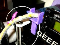
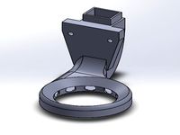
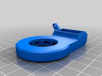
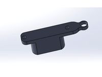
A small update, Octagon_New.123dx and OctagonProbeMount.stl
If you are using the OEM bed probe, and why not, I hadn't provided a spot for the probe. This fixes that omission.
When you open the OctagonPrint.stl file in your slicer add the OctagonProbeMount.stl file if you want the mount. The idea is to line the latter up with the former so the effector arm mounts line up exactly and combine the two in one gcode file for printing.
You will then have somewhere to screw the plate from the OEM effector head and so a mount that will function much as it did before.
Notes:
-You will need to re-calibrate the probe as the height compared to the hot end is different. Ideally you will want to change the offset in your Marlin (or other) firmware as the X/Y offset is no longer zero. For practicality's sake it doesn't matter enough to worry about.
-The mount doesn't have holes drilled for screws to attach the metal plate from the OEM effector as you'll want to finesse the fitment before screwing it in place. Screw them in when you are happy.
-I included the mount as a separate file to allow placement where you like.
What it it?
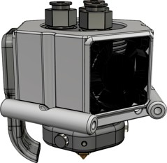
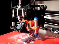
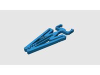
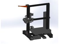
In a nut-shell it's a hot end adapter to allow a Geeetech 1 in 3 hot end to be used with an Anycubic Linear Plus delta printer.
It should work fine with any Kossel-type printer although the dimensions will need to be checked against your printer, either with a view to change your base settings or to alter the files themselves.
Why?
I like my printer, it's well dialed-in and for what it is it's very quick. As standard this printer is single filament only. There are adapters to allow the use of a Diamond hot end or sneaky 2/3 to 1 Bowden adapters for the hot end you have.
In my opinion both of these have their issues:
Diamond Hot end:
Very good, works well, but a total SOB if you get a blockage. If you can't sort it on the printer you have much dismantling to do.
2/3 to 1 Bowden adapter:
Very good for occasional multi-colour prints, I use one myself, but very wasteful of filament, colour mixing isn't possible, and getting the g-code to work reliably is no fun at all.
Geeetech's mixing hot end:
...when I came across this hot end it seemed to me to be the best of all worlds. A proper mixing hot end like the Diamond, but with a nozzle and/or mixing assembly that can be removed without pulling the whole darn thing apart. I don't know as yet but it is my hope I will be able to run nozzles of varying sizes too.
Is there a down-side? Not that I'm aware of but this hot end isn't rated for Nylon... a shame but no biggie as I now have a large core-xy printer with a huge nozzle for banging out such prints - the Anycubic printer only has to cope with the fine stuff.
The Thing:
I couldn't find an example of a Geeetech 3 in 1 to Delta adapter so I though I'd better do one myself.
-All the measurements are correct
-Tolerances have been taken in to account
-No, I haven't actually printed mine yet so Be Warned!!!
Required Parts:
1) The Control rod end mounting screws and spacers from your current set up
2) 3x M3 5mm bolts
3) A Geeetech 3 in 1 hot end - duh!
4) At least 1, preferably 2, 30mm x 8mm fans with suitable voltage
5) Three suitable lengths of 1.75mm Bowden tube
6) Three suitable extrudes - do make sure they are all the same spec!
7) The means to mount and run three reels of filament
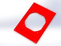
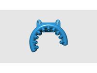
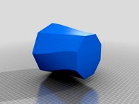
8) The printed parts: Base, shroud, print cooling attachment
9) Access to Geetech's setup files will help a lot
10) Be prepared for some jiggery-pokery
Notes:
i) I rather like the TriGorilla board that comes with the Anycubic Linear Plus but getting the poor bugger to drive three hot end heating elements, a heated bed, and three extruders is asking a lot. It can be bodged for the task, and that's exactly what I'm going to do, but if that sounds like a lot of tricky work to you then I'd strongly advise getting a more modern board that is designed for such a task.
ii) You will almost certainly need to fiddle with your firmware to add support for multiple extruders, and maybe hot end heating elements. I'm still using the 8bit version of Marlin given my driver board, but have had good luck with Klipper 3D - an excellent way to get new life out of your Arduino-based driver board assuming you have a Raspberry Pi hooked up to it.
Regardless, taking a look at Geeetech's firmware for ideas is strongly advised.
iii) You will need to set up a new profile in your slicer to take account of the extra functionality, a strait copy 'n paste from Geeetech's settings will be most of the job.
iv) When a mixing nozzle DON'T run it without filament in all three inputs even if you are only doing a single colour print.
v) Yep, there is indeed a lot to do when it comes to fitting a mixing hot end to an old printer. It's all quite doable, just take it one set at a time. Before you begin remember to ask yourself it you really need the capability? It's a lot of hassle if you don't and no matter how hard you try your printer will be less reliable as a result... hence the reason for me getting a second printer for 'workhorse' duties.
Assembly:
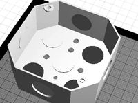
1) Having perused the included files to familiarise yourself go print out the parts included in the OctagonPrint.stl file. It's up to you whether you print them all together or separately - the fan shroud needs support for the fan openings and the print cooler needs external support but preferably not internal support. The base itself will print as-is.
I'd suggest a pretty heavy in-fill, especially for the base but otherwise whatever settings you like - just make it as accurate are strong as you can, larger layer heights tend to be stronger so there's a balance to be struck. PLA should be fine but a more heat-resistant material such as ABS is advised.
2) Having printed the parts to your satisfaction it's time to remove the old hot-end assembly along with the Bowden tube and wiring. Remember to retain the effector-arm to hot end mounting screws and spacers at the very least!
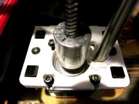
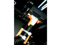
3) The Geeetech 3 in 1 assembly wants to be pushed through the hole in the effector plate from the underside such that the holes in the effector plate line up with the notches in the flat plate that is between the fin and extruder sections. Drive in four suitable screws / M3 Nuts and bolts to secure the two together.
Note: The metal plate that is part of the hot end is a little off-set so to two parts will only go together comfortably on way round, as you tighten the screws down make sure there is an even gap between the fins and the effector plate all the way round...
...There is a mistake in my model of Geeetech's hot end - the three Bowden couplers are rotated by 180deg. This is not an issue, just don't get confused when you note the parts seem to go together the other way round!
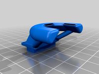
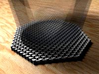
4) Assuming you fit two fans take the shroud and press-fit both fans in to their respective holes so that they are flush with the outside edge and the wires are dangling inside. The fans want to be blowing in! The 30mm fans can have a maximum depth of 8mm, less is not an issue but thicker will probably run out of clearance - do make sure you have selected fans of equivalent voltage to the ones from the OEM assembly.
The print-cooling attachment wants to be fitted to the remaining opening as per the included files.
5) The fan shroud + attached parts should press-fit in to the effector plate with a satisfying 'snap'. Do make sure the wires for the fans pass through their cut-outs to the outside!
If the screws used to attach the hot end assembly to the effector plate are too long they will hit the fans. If the fans are too thick or inset too far they won't clear the fins of the hot end assembly.
Happy? The fans should be a nice, snug, fit, but feel free to glue them in place once properly adjusted, the same for the print cooling duct. The same goes for the fan shroud assembly attachment to the effector plate.
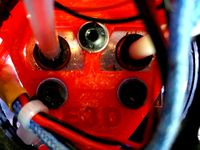
6) You now have a bunch of dangling wires. How you make your connections is up to you but you will have likely already noticed the holes in the effector plate to help neatly wrangle the wires to the top... The idea is all the wires can either be terminated where the Bowden tube couplers are (advised to make for easy maintenance) with connectors to take power & signals to the system board using the Bowden tubes for support, or carried all the way to the system board in a continuous run. Feel free to use cable ties if needed.
7) Now everything is more-or-less ready fit the whole assembly back to the effector arms just as the OEM part was fitted. You should fine the plastic holes in the effector plate are more than tight / robust enough to take the original mounting screws but feel free to use glue if you are in doubt - just don't gum up these rose-ish joints!
8) You will likely have a good idea where you want to mount your extruders and how long your Bowden tubes need to be. Just be sure all the connections are good and you have tested the extremes of movement for any snags prior to buttoning it all up.
I would advise mounting the extrudes to the top of the machine next to each-other to minimise issues, maximise neatness, and give a useful scaffolding for the hot end wiring to cling to.
Wiring:
Now comes the 'fun' part - take great care to get this right!
1) Your two fans, hopefully chosen to match the voltages of the OEM fans can be attached to the driver board exactly as the manufacturer intended.
2) The same goes for the hot end temperature probe.
But...
3) This hot end has three heating elements, not one, what the hell..?
The three hot end heating elements need to be wired up as they are intended to work together. Depending on available hardware and how much of a butcher you are you have choices:
i) Treat all three as one and connect them in parallel to a single heating element driver on the system board. This is simple, will probably work, but you may find heating is slower both because of the extra mass of the assembled hot end and having what amounts to a 'single' heating element that is three times as 'wide'. Worse, this may overload your driver board an kill it - you have been warned!
ii) The same as above you may want to add some suitable capacitors across the combined leads to help 'smooth the flow'.
iii) Buy an add in heating element supply that can be triggered by your driver board rated to supply three such elements - depending on how it works this may / may not be transparent to your software.
iv) If your driver board had two spare heating elements then now it the time use them! Some software fiddling will be needed.
v) Screw it and go get a more suitable driver board.
Thoughts:
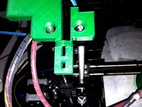
For now I have not included a proper mount for the OEM bed probe attachment. I will in due course but for now just wind the hot end nozzle down to the bed with a couple of sheets of paper in between. Take your probe and place it so it is activated on the bed itself (no paper) and mark where that will be on the hot end assembly. Glue the mount for the probe to the underside of the effector plate with however much packing you need and recheck that all is still as it should be. That will give you what I would consider a minimum probe activation height. More is not an issue, you will need to calibrate everything anyway.
The printer's firmware will absolutely need modifying and your slicer's settings will need to be update, Geeetech's own settings should prove a useful guide.
Don't forget such a setup needs three of everything, including the fillament.
Please note this design is a proof of concept - all the measurements should be fine but I've not had time to print it myself.
04.10.2020:
A small update, Octagon_New.123dx and OctagonProbeMount.stl
If you are using the OEM bed probe, and why not, I hadn't provided a spot for the probe. This fixes that omission.
When you open the OctagonPrint.stl file in your slicer add the OctagonProbeMount.stl file if you want the mount. The idea is to line the latter up with the former so the effector arm mounts line up exactly and combine the two in one gcode file for printing.
You will then have somewhere to screw the plate from the OEM effector head and so a mount that will function much as it did before.
Notes:
-You will need to re-calibrate the probe as the height compared to the hot end is different. Ideally you will want to change the offset in your Marlin (or other) firmware as the X/Y offset is no longer zero. For practicality's sake it doesn't matter enough to worry about.
-The mount doesn't have holes drilled for screws to attach the metal plate from the OEM effector as you'll want to finesse the fitment before screwing it in place. Screw them in when you are happy.
-I included the mount as a separate file to allow placement where you like.
What it it?
In a nut-shell it's a hot end adapter to allow a Geeetech 1 in 3 hot end to be used with an Anycubic Linear Plus delta printer.
It should work fine with any Kossel-type printer although the dimensions will need to be checked against your printer, either with a view to change your base settings or to alter the files themselves.
Why?
I like my printer, it's well dialed-in and for what it is it's very quick. As standard this printer is single filament only. There are adapters to allow the use of a Diamond hot end or sneaky 2/3 to 1 Bowden adapters for the hot end you have.
In my opinion both of these have their issues:
Diamond Hot end:
Very good, works well, but a total SOB if you get a blockage. If you can't sort it on the printer you have much dismantling to do.
2/3 to 1 Bowden adapter:
Very good for occasional multi-colour prints, I use one myself, but very wasteful of filament, colour mixing isn't possible, and getting the g-code to work reliably is no fun at all.
Geeetech's mixing hot end:
...when I came across this hot end it seemed to me to be the best of all worlds. A proper mixing hot end like the Diamond, but with a nozzle and/or mixing assembly that can be removed without pulling the whole darn thing apart. I don't know as yet but it is my hope I will be able to run nozzles of varying sizes too.
Is there a down-side? Not that I'm aware of but this hot end isn't rated for Nylon... a shame but no biggie as I now have a large core-xy printer with a huge nozzle for banging out such prints - the Anycubic printer only has to cope with the fine stuff.
The Thing:
I couldn't find an example of a Geeetech 3 in 1 to Delta adapter so I though I'd better do one myself.
-All the measurements are correct
-Tolerances have been taken in to account
-No, I haven't actually printed mine yet so Be Warned!!!
Required Parts:
1) The Control rod end mounting screws and spacers from your current set up
2) 3x M3 5mm bolts
3) A Geeetech 3 in 1 hot end - duh!
4) At least 1, preferably 2, 30mm x 8mm fans with suitable voltage
5) Three suitable lengths of 1.75mm Bowden tube
6) Three suitable extrudes - do make sure they are all the same spec!
7) The means to mount and run three reels of filament
8) The printed parts: Base, shroud, print cooling attachment
9) Access to Geetech's setup files will help a lot
10) Be prepared for some jiggery-pokery
Notes:
i) I rather like the TriGorilla board that comes with the Anycubic Linear Plus but getting the poor bugger to drive three hot end heating elements, a heated bed, and three extruders is asking a lot. It can be bodged for the task, and that's exactly what I'm going to do, but if that sounds like a lot of tricky work to you then I'd strongly advise getting a more modern board that is designed for such a task.
ii) You will almost certainly need to fiddle with your firmware to add support for multiple extruders, and maybe hot end heating elements. I'm still using the 8bit version of Marlin given my driver board, but have had good luck with Klipper 3D - an excellent way to get new life out of your Arduino-based driver board assuming you have a Raspberry Pi hooked up to it.
Regardless, taking a look at Geeetech's firmware for ideas is strongly advised.
iii) You will need to set up a new profile in your slicer to take account of the extra functionality, a strait copy 'n paste from Geeetech's settings will be most of the job.
iv) When a mixing nozzle DON'T run it without filament in all three inputs even if you are only doing a single colour print.
v) Yep, there is indeed a lot to do when it comes to fitting a mixing hot end to an old printer. It's all quite doable, just take it one set at a time. Before you begin remember to ask yourself it you really need the capability? It's a lot of hassle if you don't and no matter how hard you try your printer will be less reliable as a result... hence the reason for me getting a second printer for 'workhorse' duties.
Assembly:
1) Having perused the included files to familiarise yourself go print out the parts included in the OctagonPrint.stl file. It's up to you whether you print them all together or separately - the fan shroud needs support for the fan openings and the print cooler needs external support but preferably not internal support. The base itself will print as-is.
I'd suggest a pretty heavy in-fill, especially for the base but otherwise whatever settings you like - just make it as accurate are strong as you can, larger layer heights tend to be stronger so there's a balance to be struck. PLA should be fine but a more heat-resistant material such as ABS is advised.
2) Having printed the parts to your satisfaction it's time to remove the old hot-end assembly along with the Bowden tube and wiring. Remember to retain the effector-arm to hot end mounting screws and spacers at the very least!
3) The Geeetech 3 in 1 assembly wants to be pushed through the hole in the effector plate from the underside such that the holes in the effector plate line up with the notches in the flat plate that is between the fin and extruder sections. Drive in four suitable screws / M3 Nuts and bolts to secure the two together.
Note: The metal plate that is part of the hot end is a little off-set so to two parts will only go together comfortably on way round, as you tighten the screws down make sure there is an even gap between the fins and the effector plate all the way round...
...There is a mistake in my model of Geeetech's hot end - the three Bowden couplers are rotated by 180deg. This is not an issue, just don't get confused when you note the parts seem to go together the other way round!
4) Assuming you fit two fans take the shroud and press-fit both fans in to their respective holes so that they are flush with the outside edge and the wires are dangling inside. The fans want to be blowing in! The 30mm fans can have a maximum depth of 8mm, less is not an issue but thicker will probably run out of clearance - do make sure you have selected fans of equivalent voltage to the ones from the OEM assembly.
The print-cooling attachment wants to be fitted to the remaining opening as per the included files.
5) The fan shroud + attached parts should press-fit in to the effector plate with a satisfying 'snap'. Do make sure the wires for the fans pass through their cut-outs to the outside!
If the screws used to attach the hot end assembly to the effector plate are too long they will hit the fans. If the fans are too thick or inset too far they won't clear the fins of the hot end assembly.
Happy? The fans should be a nice, snug, fit, but feel free to glue them in place once properly adjusted, the same for the print cooling duct. The same goes for the fan shroud assembly attachment to the effector plate.
6) You now have a bunch of dangling wires. How you make your connections is up to you but you will have likely already noticed the holes in the effector plate to help neatly wrangle the wires to the top... The idea is all the wires can either be terminated where the Bowden tube couplers are (advised to make for easy maintenance) with connectors to take power & signals to the system board using the Bowden tubes for support, or carried all the way to the system board in a continuous run. Feel free to use cable ties if needed.
7) Now everything is more-or-less ready fit the whole assembly back to the effector arms just as the OEM part was fitted. You should fine the plastic holes in the effector plate are more than tight / robust enough to take the original mounting screws but feel free to use glue if you are in doubt - just don't gum up these rose-ish joints!
8) You will likely have a good idea where you want to mount your extruders and how long your Bowden tubes need to be. Just be sure all the connections are good and you have tested the extremes of movement for any snags prior to buttoning it all up.
I would advise mounting the extrudes to the top of the machine next to each-other to minimise issues, maximise neatness, and give a useful scaffolding for the hot end wiring to cling to.
Wiring:
Now comes the 'fun' part - take great care to get this right!
1) Your two fans, hopefully chosen to match the voltages of the OEM fans can be attached to the driver board exactly as the manufacturer intended.
2) The same goes for the hot end temperature probe.
But...
3) This hot end has three heating elements, not one, what the hell..?
The three hot end heating elements need to be wired up as they are intended to work together. Depending on available hardware and how much of a butcher you are you have choices:
i) Treat all three as one and connect them in parallel to a single heating element driver on the system board. This is simple, will probably work, but you may find heating is slower both because of the extra mass of the assembled hot end and having what amounts to a 'single' heating element that is three times as 'wide'. Worse, this may overload your driver board an kill it - you have been warned!
ii) The same as above you may want to add some suitable capacitors across the combined leads to help 'smooth the flow'.
iii) Buy an add in heating element supply that can be triggered by your driver board rated to supply three such elements - depending on how it works this may / may not be transparent to your software.
iv) If your driver board had two spare heating elements then now it the time use them! Some software fiddling will be needed.
v) Screw it and go get a more suitable driver board.
Thoughts:
For now I have not included a proper mount for the OEM bed probe attachment. I will in due course but for now just wind the hot end nozzle down to the bed with a couple of sheets of paper in between. Take your probe and place it so it is activated on the bed itself (no paper) and mark where that will be on the hot end assembly. Glue the mount for the probe to the underside of the effector plate with however much packing you need and recheck that all is still as it should be. That will give you what I would consider a minimum probe activation height. More is not an issue, you will need to calibrate everything anyway.
The printer's firmware will absolutely need modifying and your slicer's settings will need to be update, Geeetech's own settings should prove a useful guide.
Don't forget such a setup needs three of everything, including the fillament.
Similar models
thingiverse
free
Geeetech GT2560 cooling 60mm fan plate by ThomG
... cool the drivers and the other things on the board.
use tmc drivers and a silent 60mm fan to make your printer a ninja printer!
thingiverse
free

E3D versions 5 & 6 Bowden (groovemount) Hot End Mounting Plates for Rostock MAX & Orion by 626Pilot
...he time. hot wire it if you can. if you have the extruder heat turned on but the fan is turned off, the mounting plates may warp.
cg_trader
$3

Geeetech A10 Direct Drive | 3D
... require a small metal plate for moutning hot ends. holes are pre-determined for over head mounting for the adapter plate needed.
thingiverse
free

DC42 probe holder for HE3D hot end and Robotdigg effector by bgkdavis
...probe holder is specifically designed to suit the he3d hot end mounted to a robotdigg delta effector, and holds a dc42 bed probe
thingiverse
free

Chiron Volcano/Stock 5015 ducts - Endstop - Probe spacer by cana3dprint
...s and then remove it. it is too close to the heat block that any materials you can print on a standard 3d printer will just melt.
thingiverse
free
Makerfarm Pegasus E3D v6 Mount with Fan and 18mm Inductive Probe Sensor by gregington
...9;s fan shroud works with this mount, or you can use my derivative which is the same but with slightly larger fan mounting holes.
thingiverse
free

Kossel Clear Probe-less Hot End Mount by joecarpita
... end mount. see the rendered image.
i recommend using v2 of the bowden mount, but i'll leave v1 up for the purists out there.
thingiverse
free
E3D Chimera/Cyclops mount for Rostock MAX by 626Pilot
...able management (removed one wire clip and took the tang out of the other), and added some stiffening strakes to the top surface.
thingiverse
free

Cr10 Blower fan by Terminator15
...blower fan by terminator15
thingiverse
remixed to have enough room for a bowden splitter and i added a geeetech auto probe mount
thingiverse
free

E3D v6 Kossel mini effector by RalphHilton
...39;t find it necessary. i have also added files for mounting the heat bed in the think3dprint3d kit with nut traps for the bolts.
Charlesmouse
thingiverse
free
2020 Croc Clip by charlesmouse
...t for the life of me find the original! if you recognise your work here please contact me so i can include the appropriate kudos.
thingiverse
free
ANYCUBIC Kossel Delta Three PointS Filament Cooler - Remix by charlesmouse
...o print it in pla, oops, and it got a bit saggy. so if you're as daft as me here's a version with a bit of extra support.
thingiverse
free

Bong_Bong_Aircon by charlesmouse
...y on the eye, easy on the mind, and easy on the wallet. feel free to test it out and tell me if it's an utter failure or not.
thingiverse
free

Mr Toothy - A cooling duct for the Anycubic Kossel Linear Plus by charlesmouse
...er blower thingy)
so...
i thought i'd do a duct that looks a little disturbing, if not necessarily better than the stock one.
thingiverse
free

Atari 800 PI Case by charlesmouse
...e created...
...among other options.
or you could just print the whole thing as one piece at whatever size you like and paint it.
thingiverse
free

Toilet Duct for Anycubic Kossel by charlesmouse
...d access, but life would be very dull if we all had the same point of view so i did my best spin on the close-ring duct type too.
thingiverse
free

Filament Bearing for Anycubic Kossel by charlesmouse
...less, a few minutes of 'twiddling' will be needed to get them to run smoothly.
i hope you kossel owners find this useful.
thingiverse
free
Anycubic Kossel Tentacle Cooling Duct by charlesmouse
...d with a better blower. eg: see my better blower thingy.
i hope it proves useful to someone, do let me know. suggestions welcome.
thingiverse
free

Colander Cooling Duct Anycubic Kossel LInear Plus by charlesmouse
...ing, version but sadly it wouldn't fit with the hot end heat probe in place - a bit of an issue i'm sure you'l agree.
Octogon
turbosquid
$55

Gazebo Octogonal Victorian Style
... available on turbo squid, the world's leading provider of digital 3d models for visualization, films, television, and games.
3d_export
$19

Sai Octogonal Metal
...; x 0.97" x 18.2"<br>- model parts: 6<br>- material count: 2<br>- xform: yes<br>- boxtrick: yes
free3d
free

Octogon cage
...octogon cage
free3d
octogon cage
thingiverse
free

Octogonal extrusion by jordeanfoa
...nal extrusion for many things, use it for everything
octogonal 50mm
octogonal 100mm
octogonal 150mm
octogonal 200mm
enjoy it!!!!!
thingiverse
free
Octogon Vase by funkgerm
...octogon vase by funkgerm
thingiverse
just an octogonal vase i made in inventor.
thingiverse
free
Octogonal electrical box by Tstat
...octogonal electrical box by tstat
thingiverse
octogonal electrical box ( warning not for use with high voltage)
thingiverse
free
Octogonal Coaster by magiserarols
...octogonal coaster by magiserarols
thingiverse
an original coaster
thingiverse
free

Octogonal pit 4 by JJNiko
...octogonal pit 4 by jjniko
thingiverse
octogonal estilo ng con el larguero de 4 exinios. diseño de luis.
thingiverse
free

Octogonal pit 3 by JJNiko
...octogonal pit 3 by jjniko
thingiverse
ladrillo octogonal estilo ng con el larguero de 3 exinios de alto. diseño de luis.
thingiverse
free

Octogonal Wave Coaster by magiserarols
...octogonal wave coaster by magiserarols
thingiverse
an original coaster
Geeetech
3d_export
free
part right for geeetech acrylic i 3
...part right for geeetech acrylic i 3
3dexport
the engine can be shifted
3d_export
free
cable holder
...cable holder 3dexport for geeetech acrylic i...
thingiverse
free
geeetech a10 by Igor_garbuz
...geeetech a10 by igor_garbuz
thingiverse
model geeetech a10 ( solidworks).
thingiverse
free
geeetech calibration by muffler1979
...geeetech calibration by muffler1979
thingiverse
just a calibration test for the bed on a geeetech
thingiverse
free
Fan for Geeetech proB
...fan for geeetech prob
thingiverse
this is my fan for the geeetech pro b i3.
thingiverse
free

Chain for Geeetech A30
...chain for geeetech a30
thingiverse
this is my personal review of chain for geeetech a30.
thingiverse
free
Zugentlastung Hotend Geeetech A30T / Strain relief Geeetech A30T by 3DDennis1983
...zugentlastung hotend geeetech a30t / strain relief geeetech a30t by 3ddennis1983
thingiverse
zugentlastung hotend geeetech a30t
thingiverse
free
Kettenhalter i3x geeetech by Autark
...kettenhalter i3x geeetech by autark
thingiverse
geeetech i3x
thingiverse
free
Geeetech A10 Fanduct by stefan177gr
...geeetech a10 fanduct by stefan177gr
thingiverse
fanduct for geeetech a10
thingiverse
free
Geeetech filament guide by RicardoZ2018
...geeetech filament guide by ricardoz2018
thingiverse
desing for geeetech i3x