Thingiverse
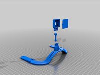
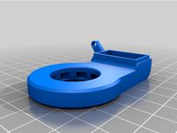
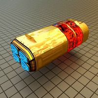
Geeetech A20M Chimear Clone (Semi) Direct Drive Mount by Abi_Jen
by Thingiverse
Last crawled date: 3 years ago
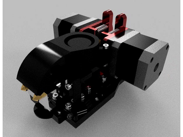
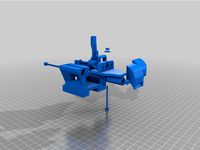
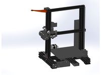
I got tired of blockages with the original 2-in 1-out hotend of my A20M and thought I'd convert to a 2-in 2-out setup, thinking of reduced waste from purging with each filament change and to have the ability to run different materials with varied temperature needs. I picked up a cheap chimera clone to play with and hit a snag with using a designed mount from here when i saw the heatbreak grub screws were in a different location to what other people have worked with. The hotend I got has the grub screws on the back face unlike the other designs where they appear to be at the sides, so using a design from here would make it impossible to adjust the nozzle heights due to the screw being impossible to access.
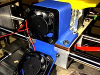
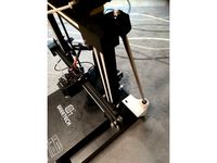
I ran the hotend initially bolting it directly to the stock x carriage with no parts fan or probe because the stock hotend blocked (again) and I needed to print some abs parts, and I found that running the chimera facing backwards worked well enough for me. The carriage has a cutout which is pretty much the perfect size for the 30mm cooling fan to mount to to get the machine usable again.
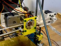
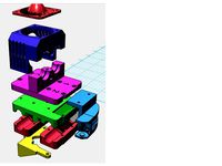
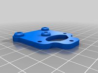
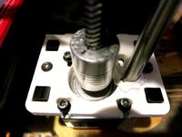
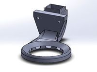
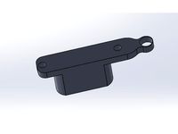
Designed in Fusion 360, This mount is designed to bolt to the original carriage, using the same holes as used for the stock hotend cage. The BLTouch mount is in the same position as the original so the offsets should be identical (ideally the mount needs adjusting in the vertical because the hotend is mounted higher that the original. This also requires the Z- endstop to be lowered sufficiently to allow the gantry to drop lower to reach the build plate). Another upgrade I had planned was to replace the 2 extruders as I didnt like where the release levers were mounted, having them inline with the filament made it awkward to feed material, and hold the lever while twisting my arm around the spool holders on the top of the frame. I picked up a pair of handed alloy extruder heads and decided to try running a semi-direct drive setup using a short bowden tube feeding the hotend.
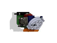
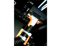
The extruder mounts are slotted to allow for movement of the bowden tubes when adjusting the height of the nozzles. The thickness of the stepper mounts is set to allow clearance for the shafts of the stepper motors that came on my original extruders, but there may be some tweaking needed for others brands etc.
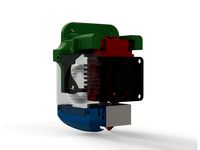
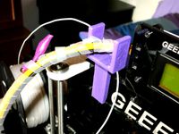
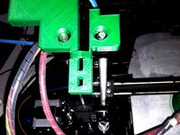
The parts fan is mounted on a hinge which allows it to be swung out of the way to access the grub screws, and also gets the parts nozzle away from the heat blocks if the fan is not running to prevent drooping with the heat (my stock fan shroud did this while printing with abs, the nozzle got hot enough to droop and strike the part). Ideally the fan mount needs to be a mm or 2 taller to move the fan slightly away from the hotend as it currently collides and doesnt sit perfectly flush which causes it to be abgled slightly. This makes no difference to how it behaves, its purely asthetic.
There are also 2 LED mounts which fit to the bottom bolts of the fan & Probe mounts, these were used for a pair of white 5mm LEDs which I plugged in to a spare cooling fan connector (with proper series resistor) for basic bed illumination. Cable clamps bolt to the Extruder mount bolts to keep the cabling tidy, which I've not used yet as I can currently only run 1 of the heaters at present (my A20M control board is a V4.1 model which doesnt have the components fitted to allow for dual heaters and is currently being replaced with a SKR GTR V1.0 and expansion board along with a TFT43 touch panel, but thats another story.
Theres also a mount for a drag chain which bolts to the reverse side of the base plate using the top 2 bolts for the extruder mounts, and is slotted to give adjustment to keep the chain level. The chain I used is a purchased one, I use larger chains at work so it was easier for me to order one from our supplier then printing my own. The chain setup I decided on runs above the x gantry and not through the centre of the frame as I found this limits the total travel height due to collisions with the top frame of the machine. This currently isnt an issue for me as my parts are small enough to not require a tall build area but i prefer not to limit the capabilities just because I dont require it right now. Chances are that if i did, then the next print i needed to do would be something that needed the extra travel. As it is right now, there is nothing that protrudes between the frame, so the gantry can travel to its full upper limit, and the carriage can travel past the 2 vertical rails, so nozzle wipe brushes etc. are an option to design if required. I've included a mount for the drag chain that bolts to the guide wheel mount on the end of the gantry too, and the mounting brackets are hopefully universal enough for other chains to bolt to without too many issues.
This is a WIP, which honestly probably wont get much of an update since I'm now toying with the idea of my own design for dual V6 hotends with servo operation to rotate the inactive nozzle clear to avoid parts strikes and ozzing, coupled with a single stepper, dual extruder setup. As it is right now, the chimera setup here works well enough for my purposes, at least until I get the SKR board fitted. Most of the tweaks I'd do to this are minor, such as moving the fan & probe mounts slightly. The 4 mounting holes to fit to the stock carriage are slightly out of position too (cheap vernier calipers with worn blades giving some poor measurements) but the base still bolts up without and major problems.
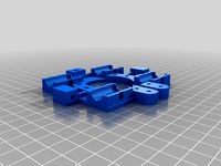
Everything was designed to be printer without supports, and to be pretty modular. It all bolts together, so if you want to change something then you dont need to redesign and print the whole thing, just the bits you want to replace. If you dont want the extruders mounted on the carriage (I have dual Z screws fitted and I dont try setting speed records with my prints so the extra weight doesnt cause issues) then its simple enough to trim down the base plate in Fusion 360 (file included). The Fusion file has everything included, the steppers, extruders, fans etc. since this is the first design I've shared here so I have no idea how it would work sharing a file with references to other designs (I'm used to Solidworks and files saved to a network location for shared access, not cloud based saving).
Assembly is using M3 and M4 nuts and cap head bolts in lengths up to 25mm (from memory), I have a couple of cheap selection boxes from eBay. The nuts are mostly captive so may require slight size adjustments to get them to fit properly. Sizing was based on the parts I had to hand.
I ran the hotend initially bolting it directly to the stock x carriage with no parts fan or probe because the stock hotend blocked (again) and I needed to print some abs parts, and I found that running the chimera facing backwards worked well enough for me. The carriage has a cutout which is pretty much the perfect size for the 30mm cooling fan to mount to to get the machine usable again.
Designed in Fusion 360, This mount is designed to bolt to the original carriage, using the same holes as used for the stock hotend cage. The BLTouch mount is in the same position as the original so the offsets should be identical (ideally the mount needs adjusting in the vertical because the hotend is mounted higher that the original. This also requires the Z- endstop to be lowered sufficiently to allow the gantry to drop lower to reach the build plate). Another upgrade I had planned was to replace the 2 extruders as I didnt like where the release levers were mounted, having them inline with the filament made it awkward to feed material, and hold the lever while twisting my arm around the spool holders on the top of the frame. I picked up a pair of handed alloy extruder heads and decided to try running a semi-direct drive setup using a short bowden tube feeding the hotend.
The extruder mounts are slotted to allow for movement of the bowden tubes when adjusting the height of the nozzles. The thickness of the stepper mounts is set to allow clearance for the shafts of the stepper motors that came on my original extruders, but there may be some tweaking needed for others brands etc.
The parts fan is mounted on a hinge which allows it to be swung out of the way to access the grub screws, and also gets the parts nozzle away from the heat blocks if the fan is not running to prevent drooping with the heat (my stock fan shroud did this while printing with abs, the nozzle got hot enough to droop and strike the part). Ideally the fan mount needs to be a mm or 2 taller to move the fan slightly away from the hotend as it currently collides and doesnt sit perfectly flush which causes it to be abgled slightly. This makes no difference to how it behaves, its purely asthetic.
There are also 2 LED mounts which fit to the bottom bolts of the fan & Probe mounts, these were used for a pair of white 5mm LEDs which I plugged in to a spare cooling fan connector (with proper series resistor) for basic bed illumination. Cable clamps bolt to the Extruder mount bolts to keep the cabling tidy, which I've not used yet as I can currently only run 1 of the heaters at present (my A20M control board is a V4.1 model which doesnt have the components fitted to allow for dual heaters and is currently being replaced with a SKR GTR V1.0 and expansion board along with a TFT43 touch panel, but thats another story.
Theres also a mount for a drag chain which bolts to the reverse side of the base plate using the top 2 bolts for the extruder mounts, and is slotted to give adjustment to keep the chain level. The chain I used is a purchased one, I use larger chains at work so it was easier for me to order one from our supplier then printing my own. The chain setup I decided on runs above the x gantry and not through the centre of the frame as I found this limits the total travel height due to collisions with the top frame of the machine. This currently isnt an issue for me as my parts are small enough to not require a tall build area but i prefer not to limit the capabilities just because I dont require it right now. Chances are that if i did, then the next print i needed to do would be something that needed the extra travel. As it is right now, there is nothing that protrudes between the frame, so the gantry can travel to its full upper limit, and the carriage can travel past the 2 vertical rails, so nozzle wipe brushes etc. are an option to design if required. I've included a mount for the drag chain that bolts to the guide wheel mount on the end of the gantry too, and the mounting brackets are hopefully universal enough for other chains to bolt to without too many issues.
This is a WIP, which honestly probably wont get much of an update since I'm now toying with the idea of my own design for dual V6 hotends with servo operation to rotate the inactive nozzle clear to avoid parts strikes and ozzing, coupled with a single stepper, dual extruder setup. As it is right now, the chimera setup here works well enough for my purposes, at least until I get the SKR board fitted. Most of the tweaks I'd do to this are minor, such as moving the fan & probe mounts slightly. The 4 mounting holes to fit to the stock carriage are slightly out of position too (cheap vernier calipers with worn blades giving some poor measurements) but the base still bolts up without and major problems.
Everything was designed to be printer without supports, and to be pretty modular. It all bolts together, so if you want to change something then you dont need to redesign and print the whole thing, just the bits you want to replace. If you dont want the extruders mounted on the carriage (I have dual Z screws fitted and I dont try setting speed records with my prints so the extra weight doesnt cause issues) then its simple enough to trim down the base plate in Fusion 360 (file included). The Fusion file has everything included, the steppers, extruders, fans etc. since this is the first design I've shared here so I have no idea how it would work sharing a file with references to other designs (I'm used to Solidworks and files saved to a network location for shared access, not cloud based saving).
Assembly is using M3 and M4 nuts and cap head bolts in lengths up to 25mm (from memory), I have a couple of cheap selection boxes from eBay. The nuts are mostly captive so may require slight size adjustments to get them to fit properly. Sizing was based on the parts I had to hand.
Similar models
thingiverse
free
Geeetech A20M Chimera Clone (almost) Direct Drive Mount by Abi_Jen
...e mostly captive so may require slight size adjustments to get them to fit properly. sizing was based on the parts i had to hand.
thingiverse
free
Printrbot Plus 1404 Extruder Fan Mount by FooFighter94
...e extruder. this design is especially useful if you are running a hotend which is shorter than the stock ubis (i have an e3d v6).
thingiverse
free
RepRap Prusa extruder fan mount by maakit
...riage and extruder in abs.
so i designed a simple mounting plate for a 4cm fan which bolts on to the bottom of the x-belt clamps.
thingiverse
free
GEEETECH A20M hotend mount for Homyl Color Switch Extruder
...necting the various connectors. https://www.amazon.ca/gp/product/b07hywxt61/ref=ppx_yo_dt_b_asin_title_o07_s00?ie=utf8&psc=1
thingiverse
free
X Carriage for E3D Nozzle by Emadine
...m and most x carriage have not enough room for it so i make this, this is for the 50mm apart smooth rod and 50mm extruder mount.
thingiverse
free
Eryone Thinker S 2in1 Extruder Mount and Cooler
...er to extrudermount
4 - m3x20mm bolt to mount 2in1 extruder to extrudermount
4 - m3x15mm bolt to mount 30mm fan to heatsinkcooler
thingiverse
free

Tevo Stock Dual Hotend Magnetic Mount by cardiac4
... setup on the dual extruder so i made this. i did shave a little off the sides so parts like fang fans would fit a little better.
thingiverse
free
Geeetech A20m mount 2in1 bigtreetech cyclops hotend by Junniec
...d nuts
if there are some pointers or requests please let me know.
(will try to add attachment for part cooling fan in the future)
thingiverse
free
Dual Extruder Mount for e3dv6 by noisyboy1308
... during the set up for dual extrusion. :d
i did not design a nozzle for material cooling yet. feel free to do so and let me know.
thingiverse
free

Mendel90 x-carriage hotend fan duct (always on, for hexagon hotend) by Stemer114
...the fan duct (towards the hotend) is for the extruder mounting to still be accessible when the duct is mounted (see 3rd picture).
A20M
thingiverse
free
A20M Frame Stabilizer by _JDK_
...a20m frame stabilizer by _jdk_
thingiverse
frame stabilizer for a20m
thingiverse
free

Bac pour Purge A20M
...bac pour purge a20m
thingiverse
bac pour purge a20m
thingiverse
free
GeeeTech A20M Screen Cover by jordanx02
...geeetech a20m screen cover by jordanx02
thingiverse
cache écran geeetech a20m
thingiverse
free

A20M Extruder Led Bar by ragzol
...a20m extruder led bar by ragzol
thingiverse
geeetech a20m extruder light bar.
thingiverse
free

Geeetech A20/A20M fan top
...geeetech a20/a20m fan top
thingiverse
geeetech a20/a20m fan top
thingiverse
free

A20M purge blade monocolor
...rge blade monocolor
thingiverse
remix of a20m purge blade dual color by mojogameplay
merged object in mono color instead of dual
thingiverse
free

Geeetech A10M/A20M hotend by Alvarito414
...mock of the geeetech hotend for geeetech a10m and a20m. it is not functional. it is made to be used as a reference for designing.
thingiverse
free

A20M End stop spacer by Chris7777
... end stop over 10mm to allow the use of a purge bucket without cutting the piece off the hotend carriage on the newer a20m model.
thingiverse
free
A20M expension board mount
...hingiverse
it's a bracket for a geeetech a20m (maybe work for the a10)
you need:
3 knurl insert nut m3x4x5
3 m3x8
have fun!!
thingiverse
free
A20M Bed Handle / PiCam Holder by icXu
...a20m bed handle / picam holder by icxu
thingiverse
geeetech a20m bed handle with raspberry pi camera mount.
Jen
3ddd
$1

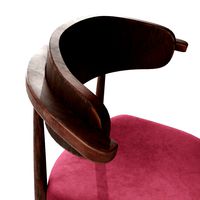
Jen
... ditre italia
современное кожаное кресло jen от ditre italia.
lenght cm 75
depth cm 75
height cm 72
3ddd
$1
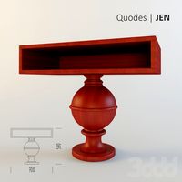
Quodes, JEN
... jen , тумба
length: 70 cm, wide: 40 cm, height: 59 cm , цвета: красный, белый, черный
turbosquid
$8
Jen chair
...lty free 3d model jen chair for download as max, obj, and fbx on turbosquid: 3d models for games, architecture, videos. (1442282)
3d_export
$6
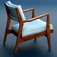
Jens Chair 3D Model
...odel
3dexport
chair armchair lounge wooden jens risom interior furnishing wood living
jens chair 3d model school73 92797 3dexport
turbosquid
$35

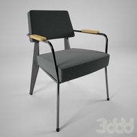
Chair Jens SJ61B
...e 3d model chair jens sj61b for download as max, obj, and fbx on turbosquid: 3d models for games, architecture, videos. (1298618)
turbosquid
$35
Chair Jens SJ61
...ee 3d model chair jens sj61 for download as max, obj, and fbx on turbosquid: 3d models for games, architecture, videos. (1298342)
turbosquid
$35
Chair Jens SJ51B
...e 3d model chair jens sj51b for download as max, obj, and fbx on turbosquid: 3d models for games, architecture, videos. (1297837)
turbosquid
$3

Wooden Ashtray JEN
... available on turbo squid, the world's leading provider of digital 3d models for visualization, films, television, and games.
3d_ocean
$15

Jens Risom Caribe Hilton Chair
...to rico, in 1949. this is based on the modern reinterpretation designed by jens and available from design within reach. the mo...
turbosquid
$10
Walnut Arm Chair by Jens Risom
...el walnut arm chair by jens risom for download as max and fbx on turbosquid: 3d models for games, architecture, videos. (1562589)
Abi
turbosquid
$3
HID ABYS
...alty free 3d model hid abys for download as max, obj, and fbx on turbosquid: 3d models for games, architecture, videos. (1466368)
turbosquid
$10
Abies Fraseri Tree
...del abies fraseri tree for download as c4d, max, fbx, and obj on turbosquid: 3d models for games, architecture, videos. (1674441)
evermotion
$20

Picea abies Plant 51 AM58
...l of plant with all textures, shaders and materials. it is ready to use, just put it into your scene.. evermotion 3d models shop.
evermotion
$20

Picea abies Plant 50 AM58
...l of plant with all textures, shaders and materials. it is ready to use, just put it into your scene.. evermotion 3d models shop.
turbosquid
$10

Snow Abies Fraseri Tree
...now abies fraseri tree for download as max, c4d, fbx, and obj on turbosquid: 3d models for games, architecture, videos. (1683079)
turbosquid
$20

Norway Spruce (Picea abies) 11.3m
... available on turbo squid, the world's leading provider of digital 3d models for visualization, films, television, and games.
turbosquid
$20

Norway Spruce (Picea abies) 1m
... available on turbo squid, the world's leading provider of digital 3d models for visualization, films, television, and games.
3d_export
$14

abies no 2
...on our user name to see complete gallery. if you have any questions, you can write to me. i will definitely answer your question.
3d_export
$14

abies no 1
...on our user name to see complete gallery. if you have any questions, you can write to me. i will definitely answer your question.
3d_export
$5

Winter Abies concolor trees
...ats<br>3ds max - vray / corona<br>cinema 4d - vray / standard<br>blender<br>obj<br>fbx<br>stl
Geeetech
3d_export
free
part right for geeetech acrylic i 3
...part right for geeetech acrylic i 3
3dexport
the engine can be shifted
3d_export
free
cable holder
...cable holder 3dexport for geeetech acrylic i...
thingiverse
free
geeetech a10 by Igor_garbuz
...geeetech a10 by igor_garbuz
thingiverse
model geeetech a10 ( solidworks).
thingiverse
free
geeetech calibration by muffler1979
...geeetech calibration by muffler1979
thingiverse
just a calibration test for the bed on a geeetech
thingiverse
free
Fan for Geeetech proB
...fan for geeetech prob
thingiverse
this is my fan for the geeetech pro b i3.
thingiverse
free

Chain for Geeetech A30
...chain for geeetech a30
thingiverse
this is my personal review of chain for geeetech a30.
thingiverse
free
Zugentlastung Hotend Geeetech A30T / Strain relief Geeetech A30T by 3DDennis1983
...zugentlastung hotend geeetech a30t / strain relief geeetech a30t by 3ddennis1983
thingiverse
zugentlastung hotend geeetech a30t
thingiverse
free
Kettenhalter i3x geeetech by Autark
...kettenhalter i3x geeetech by autark
thingiverse
geeetech i3x
thingiverse
free
Geeetech A10 Fanduct by stefan177gr
...geeetech a10 fanduct by stefan177gr
thingiverse
fanduct for geeetech a10
thingiverse
free
Geeetech filament guide by RicardoZ2018
...geeetech filament guide by ricardoz2018
thingiverse
desing for geeetech i3x
Semi
turbosquid
$65

semi
... available on turbo squid, the world's leading provider of digital 3d models for visualization, films, television, and games.
3d_export
$65

Semi 3D Model
...semi 3d model
3dexport
semi
semi 3d model modelix 59728 3dexport
3d_ocean
$19
Semi Truck
...y rim seat semi truck speed truck tyre wheel
detailed 3d model of semi truck. all materials are included. model is ready for use.
design_connected
$10

Semi Lights
...semi lights
designconnected
gubi semi lights computer generated 3d model. designed by bonderup, claus.
3ddd
$1
Gubi Semi Pendant
...gubi semi pendant
3ddd
gubi
gubi semi pendant
turbosquid
$110
Tesla Semi
...bosquid
royalty free 3d model tesla semi for download as obj on turbosquid: 3d models for games, architecture, videos. (1404184)
turbosquid
$99
Tesla Semi
...bosquid
royalty free 3d model tesla semi for download as max on turbosquid: 3d models for games, architecture, videos. (1706688)
turbosquid
free

Semi Truck
...rbosquid
free 3d model semi truck for download as ma and obj on turbosquid: 3d models for games, architecture, videos. (1397814)
turbosquid
$400

Semi Truck
...
royalty free 3d model semi truck for download as max and fbx on turbosquid: 3d models for games, architecture, videos. (1503399)
turbosquid
$50

SEMI-92
... available on turbo squid, the world's leading provider of digital 3d models for visualization, films, television, and games.
Clone
3d_export
$5
Clones great republic
...clones great republic
3dexport
clones great republic.those same clones from the star wars movie universe.4 clones available.
3d_export
$10
Clone 3D Model
...clone 3d model
3dexport
clone woman girl female lady chamber sci fi
clone 3d model calcm1 51695 3dexport
turbosquid
$5

Clone machine
... available on turbo squid, the world's leading provider of digital 3d models for visualization, films, television, and games.
archive3d
free
Clone trooper 3D Model
...nd army soldier trooper
clone trooper 2 - 3d model (*.gsm+*.3ds) for interior 3d visualization.
turbosquid
free
Lego Clone Walker
...ree 3d model lego sw clone walker for download as max and fbx on turbosquid: 3d models for games, architecture, videos. (1292252)
turbosquid
$15
Clone trooper helmet
...d model clone trooper helmet for download as ma, obj, and fbx on turbosquid: 3d models for games, architecture, videos. (1199355)
archive3d
free

Clone trooper 3D Model
...and army soldier trooper
clonetrooper 3 - 3d model (*.gsm+*.3ds) for interior 3d visualization.
archive3d
free
Clone trooper 3D Model
...and army soldier trooper
clonetrooper 1 - 3d model (*.gsm+*.3ds) for interior 3d visualization.
3d_ocean
$35

Surface Clone C4D materials
...+ of the most well made materials for maxon’s cinema 4d; on the internet today. each material is crafted with a specific purpo...
turbosquid
$3

Sci-fi cloning vats
...cloning vats for download as 3ds, obj, wrl, x, fbx, and blend on turbosquid: 3d models for games, architecture, videos. (1290168)
Direct
design_connected
free
Compas Direction
...compas direction
designconnected
free 3d model of compas direction by vitra designed by prouvé, jean.
design_connected
$18
Direction Pivotant
...direction pivotant
designconnected
vitra direction pivotant computer generated 3d model. designed by prouvé, jean.
turbosquid
$6
not direct the front
...oyalty free 3d model not direct the front for download as max on turbosquid: 3d models for games, architecture, videos. (1213034)
turbosquid
$10
Rails Direct
... available on turbo squid, the world's leading provider of digital 3d models for visualization, films, television, and games.
3d_export
$5
Picto toilet directions
...lude 3d files next to rhino6: x3dv, step, igus, obj and stl. double-sided, flipping changes the gender directions to the toilets.
3ddd
$1
fauteuli direction
...d
chair , vitra , fauteuli
fauteuli vitra chair
design_connected
$18
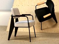
Fauteuil Direction, 1951
...fauteuil direction, 1951
designconnected
vitra fauteuil direction, 1951 computer generated 3d model. designed by prouvé, jean.
3d_export
$5
Directional tactile 3D Model
...tactile 3d model
3dexport
directional tactile braille tile flooring interior
directional tactile 3d model renob000 71068 3dexport
turbosquid
$26

Radio direction finder A
...ty free 3d model radio direction finder a for download as fbx on turbosquid: 3d models for games, architecture, videos. (1212490)
turbosquid
$7

Wooden direction signage
...ty free 3d model wooden direction signage for download as max on turbosquid: 3d models for games, architecture, videos. (1453747)
Drive
turbosquid
$90
Drive
...turbosquid
royalty free 3d model drive for download as blend on turbosquid: 3d models for games, architecture, videos. (1654393)
3d_export
$10

cycloidal drive
...cycloidal drive
3dexport
cycloidal drive
3d_ocean
$5
Flash Drive
...h drive included : – materials – scene ( lighs / room ) – .c4d + .obj for any questions please feel free to contact me thank you.
3d_ocean
$5

Usb drive
...s shaders and a lighting setup. it also has a small animation of it going in and out. i saved it out as both a .blend file and...
3d_ocean
$5

Pen Drive
...est computer drive game model good low poly new pen pen drive textured unwrapped uv very low poly
a very beautiful low poly model
3d_ocean
$10
External hard drive
... is a detailed model of a trekstor external hard drive. you can easily modify the label on the top. simply edit the text objects.
turbosquid
$60

Star Drive
...squid
royalty free 3d model star drive for download as blend on turbosquid: 3d models for games, architecture, videos. (1254314)
turbosquid
$50
Star Drive
...squid
royalty free 3d model star drive for download as blend on turbosquid: 3d models for games, architecture, videos. (1263524)
turbosquid
$45
Star Drive
...squid
royalty free 3d model star drive for download as blend on turbosquid: 3d models for games, architecture, videos. (1287060)
turbosquid
$40
Star Drive
...squid
royalty free 3d model star drive for download as blend on turbosquid: 3d models for games, architecture, videos. (1261902)
Mount
3d_export
free

mounting bracket
...mounting plate is the portion of a hinge that attaches to the wood. mounting plates can be used indoors, cabinetry and furniture.
turbosquid
$2

MOUNTING
... available on turbo squid, the world's leading provider of digital 3d models for visualization, films, television, and games.
turbosquid
free

Mounts
... available on turbo squid, the world's leading provider of digital 3d models for visualization, films, television, and games.
turbosquid
free

Mount Fuji
...fuji
turbosquid
free 3d model mount fuji for download as obj on turbosquid: 3d models for games, architecture, videos. (1579977)
3d_export
$5

Headphone mount LR
...headphone mount lr
3dexport
headphone mount l+r
turbosquid
$39

Mount rainier
...quid
royalty free 3d model mount rainier for download as fbx on turbosquid: 3d models for games, architecture, videos. (1492586)
turbosquid
$5

pipe mounting
...quid
royalty free 3d model pipe mounting for download as obj on turbosquid: 3d models for games, architecture, videos. (1293744)
turbosquid
$3

Mounting Tires
...uid
royalty free 3d model mounting tires for download as fbx on turbosquid: 3d models for games, architecture, videos. (1708511)
3d_export
$5

Magnetic GoPro Mount
...pro mount
3dexport
cool magnetic mount for gopro. allows you to mount the camera on flat metal surfaces and get exclusive shots.
turbosquid
$5

Stone Mount
...ty free 3d model stone mount for download as ma, obj, and fbx on turbosquid: 3d models for games, architecture, videos. (1370306)