Thingiverse
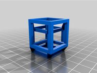
Gavitka Hypercube Evolution Alterations by MatthewB4
by Thingiverse
Last crawled date: 3 years, 2 months ago
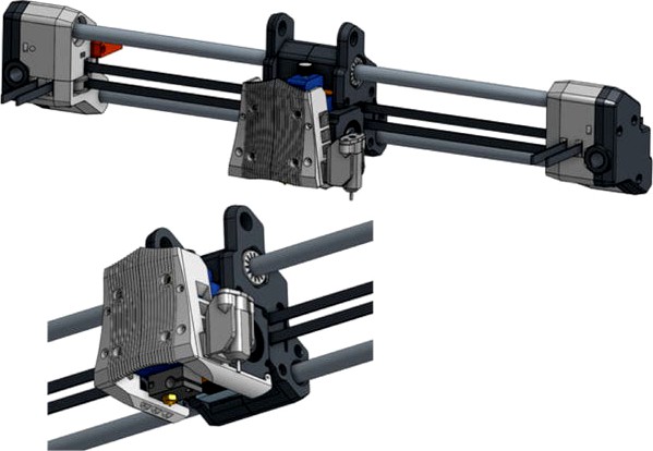
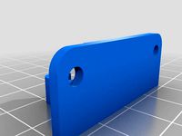
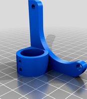
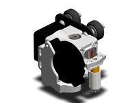
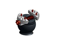
These are a couple alterations I've made to Gavitka's Hypercude Evolution design. The BLTouch mount didn't have any clearance between the mount screw head and the BLTouch. Also, with only 1 screw holding it in place it would swivel around. I've added a protrude on the wedge to prevent it from swiveling and a groove to the BLTouch mount so the screw head is inset further away from the BLTouch.
I found that I lost about 35mm of X axis using this setup so I switch to a smaller probe. I'm using an after market P.I.N.D.A. probe but the LJ8A3-2-Z will also work since it's the same size diameter.
Here's the offsets for both
For the probe:
x 49
y 48
define NOZZLE_TO_PROBE_OFFSET { 49, 48, 0 }
For the BLTouch side mount:
x 56
y -15
define NOZZLE_TO_PROBE_OFFSET { 56, -15, 0 }
I plan to add more changes to this make. I want to move the probe mount to the back of the carriage so I gain back almost all of my 300 X 300mm print area. While I'm at that I want to add some hooks and grooves to better route the wires.
Also, the part cooling duct might need to be redone. The left side is almost right up to the nozzle and heater block while the right side is quite a bit away. I don't see this being very efficient. But this is something I lack when it comes to designing.
Update;
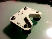
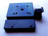
For the Y carriage I have added the locations to the inside of the parts. Example: "LT" is the Left Top, "Lb" is the Left Bottom and "LC" is for the Left End Cap. I made the holes for the 10mm linear rails slighter larger. Also, there is now more clearance for the belts and inner bearing.
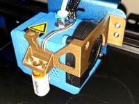
For the X carriage I have made the fit tighter around the Hemera and given the extruder wires a path underneath/along the back side. This helps keeps the wires off the bed.
*Note the wires might fit snug, I used a dull small flat-heat screwdriver to tuck them in the groove. A Popsicle stick works well too. There is also a bolt hole on the top for the 2 x carriage halves. The original design only held them together with one bolt on the bottom. I made them smaller as well so I only needed an M3 x 25.
The belt clamps have 2 purposes. They help clamp the belts down and act as an extra buffer for sensorless homing, such as with the TMC2130 or TMC2209 stepper drivers.
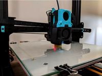
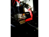
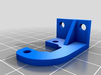
I didn't like having the BLTouch or PINDA probe on the side because it causes a 25mm to 35mm loss of print space so I made a BLTouch mount to go into the front. This gives me full probing of heat bed 300 x 300 and nearly full printable space on my heat bed. My build area is now 290 X 295Y. It doesn't look nearly as sleek in the front though, especially with all those wires. I'm still working on fine tuning the parts and how to best manage the wires. But for now I have to work on getting my slicer settings tuned.
*The offsets for the BLTouch mounted to the front are
define NOZZLE_TO_PROBE_OFFSET { 31.6, -42.4, -0.0 }
I didn't make the BLTouch mount with an adjustable height but it is set to the height recommended 8.5mm above nozzle height by ANTCLABS and it works fine for homing Z and auto bed leveling.
I found that I lost about 35mm of X axis using this setup so I switch to a smaller probe. I'm using an after market P.I.N.D.A. probe but the LJ8A3-2-Z will also work since it's the same size diameter.
Here's the offsets for both
For the probe:
x 49
y 48
define NOZZLE_TO_PROBE_OFFSET { 49, 48, 0 }
For the BLTouch side mount:
x 56
y -15
define NOZZLE_TO_PROBE_OFFSET { 56, -15, 0 }
I plan to add more changes to this make. I want to move the probe mount to the back of the carriage so I gain back almost all of my 300 X 300mm print area. While I'm at that I want to add some hooks and grooves to better route the wires.
Also, the part cooling duct might need to be redone. The left side is almost right up to the nozzle and heater block while the right side is quite a bit away. I don't see this being very efficient. But this is something I lack when it comes to designing.
Update;
For the Y carriage I have added the locations to the inside of the parts. Example: "LT" is the Left Top, "Lb" is the Left Bottom and "LC" is for the Left End Cap. I made the holes for the 10mm linear rails slighter larger. Also, there is now more clearance for the belts and inner bearing.
For the X carriage I have made the fit tighter around the Hemera and given the extruder wires a path underneath/along the back side. This helps keeps the wires off the bed.
*Note the wires might fit snug, I used a dull small flat-heat screwdriver to tuck them in the groove. A Popsicle stick works well too. There is also a bolt hole on the top for the 2 x carriage halves. The original design only held them together with one bolt on the bottom. I made them smaller as well so I only needed an M3 x 25.
The belt clamps have 2 purposes. They help clamp the belts down and act as an extra buffer for sensorless homing, such as with the TMC2130 or TMC2209 stepper drivers.
I didn't like having the BLTouch or PINDA probe on the side because it causes a 25mm to 35mm loss of print space so I made a BLTouch mount to go into the front. This gives me full probing of heat bed 300 x 300 and nearly full printable space on my heat bed. My build area is now 290 X 295Y. It doesn't look nearly as sleek in the front though, especially with all those wires. I'm still working on fine tuning the parts and how to best manage the wires. But for now I have to work on getting my slicer settings tuned.
*The offsets for the BLTouch mounted to the front are
define NOZZLE_TO_PROBE_OFFSET { 31.6, -42.4, -0.0 }
I didn't make the BLTouch mount with an adjustable height but it is set to the height recommended 8.5mm above nozzle height by ANTCLABS and it works fine for homing Z and auto bed leveling.
Similar models
thingiverse
free
ANET A8 Beefy BLTouch Mount by Mr_Dabrudda
...k_probe_bed_position 170
this mount is for the default 30mm nozzle throat. a longer or shorter throat will require modification.
thingiverse
free

E3D Hemera for Creality with TriangleLab Filament Sensor
...quot;#define nozzle_to_probe_offset { -43, -1, 0 }"
you will need 2 m3 x 30 screws and m3 nuts to mount the filament sensor.
thingiverse
free
Voron Afterburner Mod: CR-10, Single MGN12, BLTouch by HastyMantis
...o raise the belt clamps a little and try to shave about 3mm off the rear.
bltouch offsets are x=0 y=19 z~3 (for the v6 printhead)
thingiverse
free
LPA Modular X Carriage Daughter Plates with BLTouch by bkbreyme
...with the fan mount facing downward.
added additional diamond mount based on lhartmann's version with extra attachment points.
thingiverse
free
18mm ABL Mounts by CephDigital
...s designed with this in mind. if the x motor cover is smaller than the ender 3 one, it should work no problem with your printer.
thingiverse
free
Tevo Tarantula Modular X Carriage, with BLTouch, without Belt Lock by superjamie
...ouch-std-bracket-v2.stl).
when i figure out the right height for the spacer and offsets for the bltouch then i'll post those.
thingiverse
free
Fusebox beefy carriage and BLTouch mount by ccarlson71
...touch that fits between the belts on the right side of the x carriage (specifically, the remixed carriage for 1.8mm thick belts).
thingiverse
free
CR10 V2 BLTouch Centred Bracket
...ng. i have also included my modified hex file in the downloads if you want it to work like the video
https://youtu.be/qmfqblegzyk
thingiverse
free

Servo mount for Bed Level Probe by vandarin
... place for this, so i just took a small drill bit, made pilot holes in the side of the x carriage and used wood screws to attach.
thingiverse
free
Exhaust Plate BLTouch by goneeli
...
"#define nozzle_to_probe_offset {36.28, -2.91, -2 }"
update 4/4/2021
it works! probe had to move +3mm up in z. enjoy!
Matthewb4
thingiverse
free

BIGTREETECH BTT UPS 24V by MatthewB4
... shows the box with left side mounting holes. i also added an stl file with center mounting holes if others preferred it instead.
thingiverse
free
Hypercube Evolution Hemera Mount by MatthewB4
... case others prefer it. i'm using a cable chain so the other mount puts the wires in the center where the chain mount starts.
thingiverse
free

Hypercube Evolution X Y Carriage Spacer by MatthewB4
.... this spacer gives me about 1mm gap away from the motor mount and top z rod brackets.
hopefully this helps someone else as well.
Gavitka
thingiverse
free
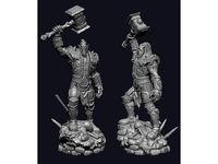
Thrall by Gavitka
...thrall by gavitka
thingiverse
did not test yet, but others made it, so should be ok
thingiverse
free

Backlash spool holder by Gavitka
...backlash spool holder by gavitka
thingiverse
backlashing spool holder to keep filament in tame. ticks.
thingiverse
free

drag chain by Gavitka
...55mm.
cad files: https://cad.onshape.com/documents/765e0e327620da1d032387b4/w/b050c411b851a77339afa70d/e/7626ff358f047c65b705690a
thingiverse
free

wire stripper by Gavitka
...ures:
quite comfy
boom!:
2x - m3x8mm screw
1x - m5x8mm screw
2x - 9mm utility knife blade 4 sections
~5mm od ~ 20mm length spring
thingiverse
free

Custom VORON V0 toolhead by Gavitka
...gon only
source: https://cad.onshape.com/documents/430093947fc23398bb400422/w/3b5dbde7e113779f21d33f74/e/06bd657d744d3c10ebe4fedf
thingiverse
free
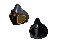
Filter mask more airflow by Gavitka
...lve.
cad source: https://cad.onshape.com/documents/0903a768e8c078c9c97c9871/w/5189403e141e4cedb755a555/e/652982114f1e4c8e8d18b2a5
thingiverse
free
Ball vise by Gavitka
...ugh.
cad source: https://cad.onshape.com/documents/c19bb66f73c46cf9e94162c5/w/ea313e0d2af07d19b1dbf5f7/e/c3029f58f7d9ad59794d7316
thingiverse
free
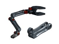
Heavy duty mounting system by Gavitka
...ystem
cad source:https://cad.onshape.com/documents/174e55e163610a403d8be97b/w/df00e3ac86eb42bfb502b90c/e/3223e83c4918a474ded435a5
thingiverse
free

Jointed female figure by Gavitka
...tead.
my printer is configured as follows:
0.2 mm tolerance - loose fit
0.1 mm tolerance - tight fit
0.0 mm tolerance - press fit
thingiverse
free

3d printer WIP by Gavitka
... available here: https://cad.onshape.com/documents/9a3b38e0a88e8abf7e12be2c/w/cdab6c3c4e4b7cdb98cdb328/e/6500a54671f819f1edabf3c2
Hypercube
turbosquid
free

HyperCube
... available on turbo squid, the world's leading provider of digital 3d models for visualization, films, television, and games.
3d_export
$5
Hypercube 3D Model
...hypercube 3d model
3dexport
cube hypercube four-dimensional space side geometry edge
hypercube 3d model dmitry87 54991 3dexport
3d_export
$5
tesseract hypercube
...t it. moreover different textures and materials can be added and tesseract can be set in any scene. dimensions: x: 4m y: 4m z: 4m
thingiverse
free
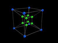
Hypercube
...hypercube
thingiverse
hypercube projected into three dimensional space.
thingiverse
free

Hypercube by alpheccar
...hypercube by alpheccar
thingiverse
projection of an hypercube on an hypersphere.
thingiverse
free
Hypercube by BorisBlavasky
...hypercube by borisblavasky
thingiverse
hypercube. testing the tool.
thingiverse
free

Hypercube by Christian42
...hypercube by christian42
thingiverse
i made a hypercube using rhino3d
thingiverse
free

Hypercube by Christian42
...hypercube by christian42
thingiverse
i made a hypercube using rhino3d
thingiverse
free

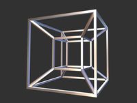
HyperCube by wwebber
...hypercube by wwebber
thingiverse
this is the standard perspective projection of the hypercube from 4d to 3d
thingiverse
free
HyperCube scaled by Muzeem
...hypercube scaled by muzeem
thingiverse
customized hypercube
Evolution
3ddd
$1
Evolution
... evolution , комод
комод из каталога emmemobili модель evolution
design_connected
$18
Evolution
...evolution
designconnected
zanotta evolution computer generated 3d model. designed by ïto, ora.
design_connected
$11

Evolute
...evolute
designconnected
danese evolute computer generated 3d model. designed by crasset, matali.
design_connected
$22

Evolution
...evolution
designconnected
emmemobili evolution shelves and storage computer generated 3d model. designed by ferruccio laviani.
3ddd
$1

Zanotta / EVOLUTION
...zanotta / evolution
3ddd
zanotta
zanotta
884 evolution
3ddd
free
Simas Evolution
...simas evolution
3ddd
simas
раковина simas evolution
3ddd
$1

Lancer Evolution
...lancer evolution
3ddd
автомобиль , машина
lancer evolution viii
3ddd
$1
Zanotta Evolution
...zanotta evolution
3ddd
zanotta
современное кресло evolution фабрики zanotta
turbosquid
$25
Evolution Dragon
...d
royalty free 3d model evolution dragon for download as obj on turbosquid: 3d models for games, architecture, videos. (1212928)
turbosquid
$6

Flowers Evolution
...
royalty free 3d model flowers evolution for download as obj on turbosquid: 3d models for games, architecture, videos. (1214159)
Alterations
turbosquid
$2
Alter
... available on turbo squid, the world's leading provider of digital 3d models for visualization, films, television, and games.
turbosquid
$1

Alter
... available on turbo squid, the world's leading provider of digital 3d models for visualization, films, television, and games.
3d_export
free
alter building
...alter building
3dexport
alter building 3d model good quality for animation
3d_export
$5
alter sacrificial platform
...alter sacrificial platform
3dexport
alter or platform. stone steps with centre alter<br>blender file included
turbosquid
$20

alter eco
... available on turbo squid, the world's leading provider of digital 3d models for visualization, films, television, and games.
3ddd
free
Corbett - Alter Ego
...corbett - alter ego
3ddd
corbett
сайт www.corbettlighting.com/contents/viewitem.asp?idproduct=853
3ddd
$1

Alter Ego - Pianca
...alter ego - pianca
3ddd
pianca
http://www.urbansuite.co.uk/alterego-bed-by-pianca.html
3d_ocean
$7

Dragon asia alter
...u can easy to hang it on the wall and put some more items on this surface. its also got a small censer with the dragon pattern...
turbosquid
$20

Alter London Linden Barstool
...odel alter london linden barstool for download as max and fbx on turbosquid: 3d models for games, architecture, videos. (1298606)
turbosquid
$28

Alter London Warwick Chair
...r london warwick chair for download as 3ds, max, obj, and fbx on turbosquid: 3d models for games, architecture, videos. (1413457)