Thingiverse
G2S Universal Effector Lazer Zprobe by wbrucem
by Thingiverse
Last crawled date: 4 years, 4 months ago
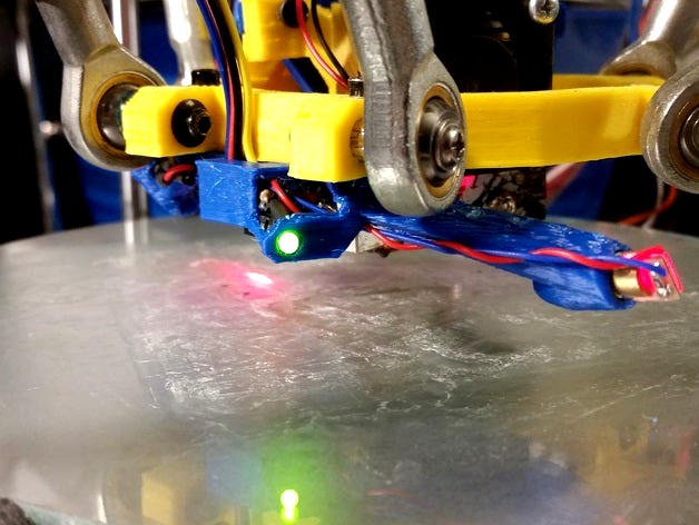
I said I wasn't planning to design a Z-probe, but inspiration struck and this is the result. This "probe" uses a laser diode beam, projected at a shallow angle, to measure a fixed height, approximately 30mm below the surface to which it is mounted. The laser spot moves horizontally approximately 9mm for each millimeter of vertical movement. A trigger condition (HIGH) is signaled when the light sensor "sees" the laser spot come into its view.
There is an enable input which may be driven directly from an Arduino output pin to activate (HIGH) or deactivate (LOW) the laser. For manual control, you may either switch the Enable line to ground to turn the laser off, or simply switch the 5 volt power supplied to the circuit.
Because this is an optical device, it can be affected by the type of surface material being measured. It works great on blue tape or glass with glue stick applied. I assume aluminum with glue stick should also work well but I am unable to test that. Performance on clean aluminum, BuildTak, etc. is unknown at this time. Clean glass does not work well, and addition of hair spray does not help significantly. Be careful to remove any loose debris from the bed before probing, as these could cause false triggering.
CAUTION: Laser light can be hazardous to your eyes. Even these relatively low power diodes are capable of causing headaches and temporary blind spots.
You will need some additional components and soldering skills to assemble this device. Here is a list of components I used:
ATtiny85 micro controller
8-pin dual in-line chip socket
6mm laser diode
Light sensitive resister
3mm green LED (trigger indicator)
1K resistor
220 resistor
39K resistor
Since the ATtiny85 is a bare chip (rather than an Arduino board), you will need an In-System-Programmer (ISP) to write the LazerRanger.ino sketch into it. These programmers are inexpensive and readily available from many vendors. You can also configure almost any Arduino board for use as an ISP, as shown here and here. You will need to load some support data into your Arduino IDE, which makes ATtiny devices appear in the "Boards" list. This is also covered in the ISP tutorials above. Be sure to select the "ATtiny85, 8MHz Internal clock" and burn the bootloader to configure the chip for higher speed operation.