Thingiverse
FT Goblin Parts by nesteffe
by Thingiverse
Last crawled date: 3 years, 1 month ago
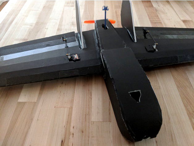
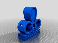
These are some parts I modeled for use with the FT Goblin.
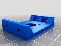
There are two versions of the firewall, one for motors with 16mm spacing for their screws and one for motors that have 16mm spacing for one pair of screws and 19mm for the other. My DYS motor uses 16x16, while a Racerstar I have uses 19x16. If your motor has different spacing this is easy to modify in the SCAD file by using the screw_spacing_h and screw_spacing_v parameters to the firewall module.
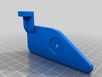
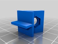
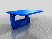
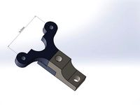
My previous camera mount was almost directly modeled off of the balsa version, just 3D printed as a solid piece. After a tree jumped out in front of where I was flying I redesigning the camera mount into a two piece system. Now the base can be hot glued into the body and the front part of the mount can be attached with M3 screws. If the camera mount is damaged you can simply print the front half again and swap to the new one without having to try cutting the old one off and attempting to re-glue the new one. The camera mount is designed for use with micro cameras that are 20mm wide, while the large one is for cameras that are 26mm wide, although I didn't have one handy to test with so your results may vary. The base uses M3 heat set inserts which can be found many places, such as Amazon and are installed by setting them over the hole and heating them with a soldering iron until they sink into place.
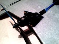
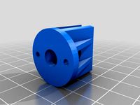
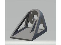
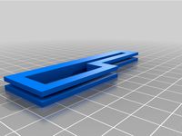
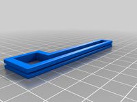
The flight controller mount is designed to have the legs fed from the inside of the plane body through the top of the battery bay so the FC can be mounted in the space between the body and the top of the nose cone. I held it in place with the self-adhesive velcro that holds my battery in place. The holes should be tapped with an M3 tap and normal M3 screws can be used. While an FC is not required I wanted one for the OSD, and having some stabilization is nice with how twitchy this plane can be.
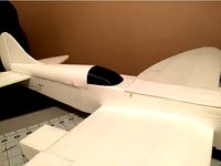
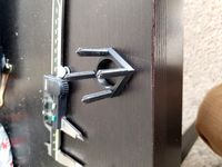
As seen in the pictures I mounted my VTX antenna in the back, protruding through the vent and secured to the rear of the wing. The foam was not strong enough to hold the antenna so I created a pair of washers to support it. The foam was also too thick for the threads on my antenna extension so I had to make the funky bottom washer which needs to be set into the foam by cutting out a 16mm hole for it to recess into. That should be the only piece which requires supports to print.
My control horn is designed to be used with adjustable pushrod connectors but could easily be used with just normal wire if you adjust the hole sizes. I would recommend cutting away the paper underneath were the control horn mounts as you will get better adhesion with less risk of the paper delaminating from the foam.
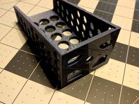
The wing opening reinforcement STL is by CapnBry. I highly recommend adding these to reduce the chances of the plane body shearing in half at the wing opening in the event of an unscheduled nose-first landing, not that I would know anything about that.
Print settings don't matter a whole lot on most of the parts, but I would do the firewall with more top/bottom layers and >=50% infill. As mentioned before, the VTX antenna bottom washer will require supports to print.
There are two versions of the firewall, one for motors with 16mm spacing for their screws and one for motors that have 16mm spacing for one pair of screws and 19mm for the other. My DYS motor uses 16x16, while a Racerstar I have uses 19x16. If your motor has different spacing this is easy to modify in the SCAD file by using the screw_spacing_h and screw_spacing_v parameters to the firewall module.
My previous camera mount was almost directly modeled off of the balsa version, just 3D printed as a solid piece. After a tree jumped out in front of where I was flying I redesigning the camera mount into a two piece system. Now the base can be hot glued into the body and the front part of the mount can be attached with M3 screws. If the camera mount is damaged you can simply print the front half again and swap to the new one without having to try cutting the old one off and attempting to re-glue the new one. The camera mount is designed for use with micro cameras that are 20mm wide, while the large one is for cameras that are 26mm wide, although I didn't have one handy to test with so your results may vary. The base uses M3 heat set inserts which can be found many places, such as Amazon and are installed by setting them over the hole and heating them with a soldering iron until they sink into place.
The flight controller mount is designed to have the legs fed from the inside of the plane body through the top of the battery bay so the FC can be mounted in the space between the body and the top of the nose cone. I held it in place with the self-adhesive velcro that holds my battery in place. The holes should be tapped with an M3 tap and normal M3 screws can be used. While an FC is not required I wanted one for the OSD, and having some stabilization is nice with how twitchy this plane can be.
As seen in the pictures I mounted my VTX antenna in the back, protruding through the vent and secured to the rear of the wing. The foam was not strong enough to hold the antenna so I created a pair of washers to support it. The foam was also too thick for the threads on my antenna extension so I had to make the funky bottom washer which needs to be set into the foam by cutting out a 16mm hole for it to recess into. That should be the only piece which requires supports to print.
My control horn is designed to be used with adjustable pushrod connectors but could easily be used with just normal wire if you adjust the hole sizes. I would recommend cutting away the paper underneath were the control horn mounts as you will get better adhesion with less risk of the paper delaminating from the foam.
The wing opening reinforcement STL is by CapnBry. I highly recommend adding these to reduce the chances of the plane body shearing in half at the wing opening in the event of an unscheduled nose-first landing, not that I would know anything about that.
Print settings don't matter a whole lot on most of the parts, but I would do the firewall with more top/bottom layers and >=50% infill. As mentioned before, the VTX antenna bottom washer will require supports to print.
Similar models
thingiverse
free
RC plane firewall by bifi5590
...through the side holes.
i highly recommend printing this in abs because the pla version of this deformes when the motor gets hot.
thingiverse
free
Basic RC Plane Motor Mount/Firewall by markcr
...tc.
can be mounted over or inbetween a fuse/front walls.
i used this to repair a shattered plywood motor mount and it worked well
thingiverse
free
RMRC Ready Made RC Recruit V2 VTX Antenna Holder and Crossfire Antenna Holder by QuadView
...ng while you place on and off your antenna. many revisions to get the fit perfect. tell me if you think i can improve on it more.
thingiverse
free

Bixler 2 FPV mount by MiguelAlvarez
...e screwing on the antenna. the vtx holder is made for my 400mw rmrc vtx but if requested i can modify it for a different size tx.
thingiverse
free
Fixed wing VTX SMA mount
...fixed wing vtx sma mount
thingiverse
i use these to mount a vtx antenna on a plane.
thingiverse
free
AXII Stubby Antenna Mount by Maxxborg
... this to mount the axii stubby antenna on my trx4 i made to screw holes to mount it to the body. i use an extension to the vtx
thingiverse
free

Nutball motor mount flight test pattern by BuiltBrokenGlued
...e.com/thing:2748008
if anyone has another hole size required and different size foam i can adjust this and post it up on request.
thingiverse
free
1806 Motor Mount for Foam Board by Cycad_Tech
...gthening the area around the motor mount. this will help stop the foam from creasing in the area directly around the motor mount.
thingiverse
free

RC Plane Brushless Motor Mount 16 x 19mm by jangy
...dio control airplane for brushless motors hole spacing 16mm x 19mm.
use to mount 22xx multicopter motor to a rc airplane firewall
thingiverse
free

Super Bee Motor Pods by Mid7night
...holes are sized for emax rs2205, rs2306, and any similar sized motors with 16mm x 19mm hole spacing and...
Goblin
thingiverse
free

Goblin
...goblin
thingiverse
a lil goblin
thingiverse
free

Goblin
...goblin
thingiverse
it tried sculpting a goblin. i think it went ok.
thingiverse
free
goblin
...goblin
thingiverse
fixed, posed models of the goblin mob from darksiders genesis
thingiverse
free
goblin warboss head - night goblins - gubbins
...goblin warboss head - night goblins - gubbins
thingiverse
goblin warboss - night goblins
thingiverse
free
Goblin Mechdriver
...goblin mechdriver
thingiverse
inspired by the goblin shredders from world of warcraft. :]
goblin 29 of gobtober!
thingiverse
free
Tesque The Goblin
...tesque the goblin
thingiverse
tesque the goblin.
thingiverse
free

Goblin Samurai
...goblin samurai
thingiverse
goblin samurai
thingiverse
free

Goblin Rogue
...goblin rogue
thingiverse
goblin rogue
thingiverse
free

Goblin by Yaxin
...goblin by yaxin
thingiverse
a model of goblin
thingiverse
free

Goblin undertaker
...goblin undertaker
thingiverse
a more friendly goblin than usual, gavin the undertaker!
goblin 14 of gobtober!
Ft
thingiverse
free

ft by Colemanc
...ft by colemanc
thingiverse
fh
thingiverse
free
FT-5 XY (core xy ft-5) by h1hummerh3t
...y ft-5) by h1hummerh3t
thingiverse
this is a conversation for the folgertech ft-5 making it into a corexy. by me- william puchot
thingiverse
free
FT Firewall V3 by TobiMay
...for ft versa wing with less air resistance than the original design
inspired by http://flitetest.com/articles/ft-versa-wing-build
thingiverse
free
Yaesu FT-8800/FT-8900 Faceplate Mount by mbilke
...unt by mbilke
thingiverse
i was looking for a way to mount the detachable faceplate for my ft-8900 and had a buddy draw this up.
thingiverse
free

Yaesu FT-2 FT-3 desk stand by waheiko
...yaesu ft-2 ft-3 desk stand by waheiko
thingiverse
desk stand for yaesu handhelds
thingiverse
free

ft edge tail support
...ft edge tail support
thingiverse
ft edge tail support
thingiverse
free

ft-5 idler by RamonSeda
...ft-5 idler by ramonseda
thingiverse
just an ft-5 idler
thingiverse
free

FT arrow fuselage
...fuselage
thingiverse
custom fuselage for ft arrow.
i glued the wing directly to the fuselage with hot glue,
the motor is a 1806.
thingiverse
free
FT Cruiser Canopy by RickPeck
...ft cruiser canopy by rickpeck
thingiverse
this is a canopy for the larger ft cruiser. not for the mini.
thingiverse
free
FT Spear Firewall by shniggysaurus
...verse
this is the firewall for flite tests ft spear. its actually just a remix of cannerbals ft firewall made to fit the spear.
Parts
thingiverse
free
part part part by ease
...part part part by ease
thingiverse
part part part
thingiverse
free
part
...part
thingiverse
part
thingiverse
free

part
...part
thingiverse
3d test fan part
thingiverse
free
part
...part
thingiverse
part i made for friend
thingiverse
free

Turbo Part by part by Thellgti
...turbo part by part by thellgti thingiverse turbocharger in parts ...
thingiverse
free
Part Stand Part Holder
...is a part holder i designed for holding small parts for painting can be scaled up or down to...
thingiverse
free

Part by WizxGamer
...part by wizxgamer
thingiverse
part
thingiverse
free
PART by leonk
...part by leonk
thingiverse
part
thingiverse
free

Part by empirekitchen
...part by empirekitchen
thingiverse
part
thingiverse
free

part by migueljb01
...part by migueljb01
thingiverse
part