Thingiverse
FT-5 Enclosure Braces for 1/8in acrylic by Fickert
by Thingiverse
Last crawled date: 3 years ago
!Disclosure! I list measurements from my personal machine, BUT, a large but, your machine may differ than mine. Before chopping up your probably not cheap acrylic sheets, please do your own measuring and use mine as a reference.
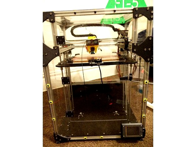
Okay I will try to describe this the best I can. First this enclosure is for The FolgerTech FT-5 and using a bowden setup with a e3d titan extruder. This may work with the stock extruder but not certain. Test it out and see :)
First I will go over the Bill of Materials.
BOM List:
x1-Extruder Mount
x3-Universal Hinges -----> http://www.thingiverse.com/thing:1209695
x1-Latch Assembly ------> http://www.thingiverse.com/thing:1844744
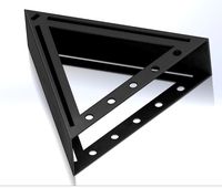
x6-T Brace
x1-Left T Brace with Front Brace
x1-Right T Brace with Front Brace
x1-Left Corner Brace with Front Brace
x1-Right Corner Brace with Front Brace
x7-Right Corner Brace
x6-Left Corner Brace
x1-TFT32 Mount Rev 2 (If no TFT32, Then replace this part with x1 Left Corner Brace)
x2-24in x 48in x 1/8in thick Sheet of Acrylic, PolyCarbonate, or Lexan
x1-Extra T Nuts (need a lot) --------> https://www.amazon.com/gp/product/B019ZXUSY0/ref=oh_aui_detailpage_o06_s01?ie=UTF8&psc=1
x1-Extra Screws (Also need a lot) --------> https://www.amazon.com/gp/product/B01G9HUYJO/ref=oh_aui_detailpage_o06_s00?ie=UTF8&psc=1
x2-64 Screw Caps
x2-Filament holders -------> http://www.thingiverse.com/thing:1813903
x1-16mm tube of >500mm for Spool holder
To assemble this together first printout/purchase all of the parts pertaining to this build. It will also be extremely wise to purchase or use a jigsaw to cut the acrylic. Use metal blades. This is the unit I used but of course buy or use what you would like ------> http://www.homedepot.com/p/Ryobi-6-1-Amp-Variable-Speed-Orbital-Jigsaw-with-Speed-Match-JS651L1/203146378
First is to cut the acrylic to size. There is a specifc way to cut the parts and I cannot model them up currently so I will try to describe it the best I can for now.
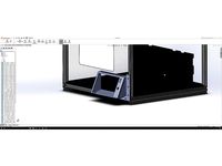
To start the measurements given can be off by roughly 1/16in - 1/8in maximum otherwise it will look like poo and not line up correctly. Use as many of the precut straight edges of the acrylic as you can. And only measure from precut edges. The goal is to figure out how to fit all the parts on the two sheets of acrylic you purchased. I did but I do not recall how I did. A quick sketch in CAD should do the trick for most.
First the front of the machine is all a single piece. So cut out that shape. Should be about 28 1/4in x 21 1/4in.
The Top is also a single piece. Size is 21 1/4in x 19 3/4in
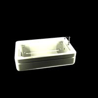
The sides and rear I divided into two pieces; the lower section and the upper section. These sections I designate are divided by the 2020 that mounts the linear rails for the y axis. So cut a piece to fit into each section while still covering have of the middle 2020 piece ( added photos to help with this) Do this for the sides and rear. The rear you need to stop short of the power supply and mks board bay.
Sizes as follows:
Sides:
-Lower: 19 5/8in x 20 7/8in.
-Upper: 19 5/8in x 7 3/8in
Rear:
-Lower: 21 /14in x 13 3/8in
-Upper: 21 1/4in x 7 3/8in
The Last piece will be the door. I have my door at 13in x 20in and centered on the front piece. DO NOT TRY TO ENLARGE ABOVE 13in WIDE, IT WILL NOT WORK. Really I do not advise enlarging it at all from my measurements. It is a perfect size and you do not have much room to enlarge it (height wise).
Before final assembly two more things I will mention. First MAKE SURE YOUR PRINTER IS COMPLETELY SQUARED UP. Double check every measurement. I found my right y-axis linear rail was 1/8 inch lower than the left one. As well, remove the front middle 2020 section and cut it up. Note please make your own measurements for these as these can vary for each printer. My measurements are just for reference.
x2-2 7/8in sections
x2-6 1/4in sections
Hopefully you can figure out where these fit into ;)
Finally the assembly is fairly self explanatory. Lay the printer on its side so that the side you are working on it face-up. Makes a much easier platform to work on as it will not slide off or anything.
Align each section in their designated area. Place the coordinating braces in their positions so that the holes are centered over the groove of the 2020. Mark each hole with a sharpy and drill them out. Match the drill bit size with the hole size in the braces. Do this step for all the braces. I recommend lightly mounting on corner and then finish the section. Makes it much easier to drill the rest without the acrylic sliding around. (Note: when drilling rule of thumb. Make sure you drill all the way through, and quickly. When you pierce the arcylic and the drill bit puts a mark on the 2020 it is very convenient to use those marks later to put the t-nuts in) The additional screws that will use the screw caps (yellow squares in my pictures) you can just guesstimate or measure where these go. Feel what you think looks right. This is just to make sure the acrylic is completely fastened onto the frame.
When you get to marking up the top section, dont forget to drill out the slot for the motor wire to run though the acrylic. The Extruder mount uses that small slot in the stepper motor bay. As well don't forget to cut around the Spool mount holders which will need clearance since the mount on the inside of the FT-5 Frame (as pictured as well)
Okay so you now have all the mounting holes drilled out. Next will be to cut out a clearance guide slot for the bowden tube. Take one of the upper side sections, and drill two holes spaced out to whatever you find will work. I think mine are 14 inches apart with a 1/2 bit. After those holes are drilled, use the jigsaw and cut from one hole to the other creating a slot like pictured.
Another two holes to cut out are for the power plug as well as the usb for the mks board. Create slots the best of your ability.
The final cutting that will be needed is the door section cut out of the front section. Center up the shape of the door to the best you can (I would measure it all out and outline it with sharpy on the acrylic first.) And cut that out.
You should have no problems getting the rest of the enclosure sorted out (Door hinges and latch) mounted if you have made it this far.
Any questions please ask me on here or in the FolgerTech Forum/ Facebook Group.
Cheers!
Okay I will try to describe this the best I can. First this enclosure is for The FolgerTech FT-5 and using a bowden setup with a e3d titan extruder. This may work with the stock extruder but not certain. Test it out and see :)
First I will go over the Bill of Materials.
BOM List:
x1-Extruder Mount
x3-Universal Hinges -----> http://www.thingiverse.com/thing:1209695
x1-Latch Assembly ------> http://www.thingiverse.com/thing:1844744
x6-T Brace
x1-Left T Brace with Front Brace
x1-Right T Brace with Front Brace
x1-Left Corner Brace with Front Brace
x1-Right Corner Brace with Front Brace
x7-Right Corner Brace
x6-Left Corner Brace
x1-TFT32 Mount Rev 2 (If no TFT32, Then replace this part with x1 Left Corner Brace)
x2-24in x 48in x 1/8in thick Sheet of Acrylic, PolyCarbonate, or Lexan
x1-Extra T Nuts (need a lot) --------> https://www.amazon.com/gp/product/B019ZXUSY0/ref=oh_aui_detailpage_o06_s01?ie=UTF8&psc=1
x1-Extra Screws (Also need a lot) --------> https://www.amazon.com/gp/product/B01G9HUYJO/ref=oh_aui_detailpage_o06_s00?ie=UTF8&psc=1
x2-64 Screw Caps
x2-Filament holders -------> http://www.thingiverse.com/thing:1813903
x1-16mm tube of >500mm for Spool holder
To assemble this together first printout/purchase all of the parts pertaining to this build. It will also be extremely wise to purchase or use a jigsaw to cut the acrylic. Use metal blades. This is the unit I used but of course buy or use what you would like ------> http://www.homedepot.com/p/Ryobi-6-1-Amp-Variable-Speed-Orbital-Jigsaw-with-Speed-Match-JS651L1/203146378
First is to cut the acrylic to size. There is a specifc way to cut the parts and I cannot model them up currently so I will try to describe it the best I can for now.
To start the measurements given can be off by roughly 1/16in - 1/8in maximum otherwise it will look like poo and not line up correctly. Use as many of the precut straight edges of the acrylic as you can. And only measure from precut edges. The goal is to figure out how to fit all the parts on the two sheets of acrylic you purchased. I did but I do not recall how I did. A quick sketch in CAD should do the trick for most.
First the front of the machine is all a single piece. So cut out that shape. Should be about 28 1/4in x 21 1/4in.
The Top is also a single piece. Size is 21 1/4in x 19 3/4in
The sides and rear I divided into two pieces; the lower section and the upper section. These sections I designate are divided by the 2020 that mounts the linear rails for the y axis. So cut a piece to fit into each section while still covering have of the middle 2020 piece ( added photos to help with this) Do this for the sides and rear. The rear you need to stop short of the power supply and mks board bay.
Sizes as follows:
Sides:
-Lower: 19 5/8in x 20 7/8in.
-Upper: 19 5/8in x 7 3/8in
Rear:
-Lower: 21 /14in x 13 3/8in
-Upper: 21 1/4in x 7 3/8in
The Last piece will be the door. I have my door at 13in x 20in and centered on the front piece. DO NOT TRY TO ENLARGE ABOVE 13in WIDE, IT WILL NOT WORK. Really I do not advise enlarging it at all from my measurements. It is a perfect size and you do not have much room to enlarge it (height wise).
Before final assembly two more things I will mention. First MAKE SURE YOUR PRINTER IS COMPLETELY SQUARED UP. Double check every measurement. I found my right y-axis linear rail was 1/8 inch lower than the left one. As well, remove the front middle 2020 section and cut it up. Note please make your own measurements for these as these can vary for each printer. My measurements are just for reference.
x2-2 7/8in sections
x2-6 1/4in sections
Hopefully you can figure out where these fit into ;)
Finally the assembly is fairly self explanatory. Lay the printer on its side so that the side you are working on it face-up. Makes a much easier platform to work on as it will not slide off or anything.
Align each section in their designated area. Place the coordinating braces in their positions so that the holes are centered over the groove of the 2020. Mark each hole with a sharpy and drill them out. Match the drill bit size with the hole size in the braces. Do this step for all the braces. I recommend lightly mounting on corner and then finish the section. Makes it much easier to drill the rest without the acrylic sliding around. (Note: when drilling rule of thumb. Make sure you drill all the way through, and quickly. When you pierce the arcylic and the drill bit puts a mark on the 2020 it is very convenient to use those marks later to put the t-nuts in) The additional screws that will use the screw caps (yellow squares in my pictures) you can just guesstimate or measure where these go. Feel what you think looks right. This is just to make sure the acrylic is completely fastened onto the frame.
When you get to marking up the top section, dont forget to drill out the slot for the motor wire to run though the acrylic. The Extruder mount uses that small slot in the stepper motor bay. As well don't forget to cut around the Spool mount holders which will need clearance since the mount on the inside of the FT-5 Frame (as pictured as well)
Okay so you now have all the mounting holes drilled out. Next will be to cut out a clearance guide slot for the bowden tube. Take one of the upper side sections, and drill two holes spaced out to whatever you find will work. I think mine are 14 inches apart with a 1/2 bit. After those holes are drilled, use the jigsaw and cut from one hole to the other creating a slot like pictured.
Another two holes to cut out are for the power plug as well as the usb for the mks board. Create slots the best of your ability.
The final cutting that will be needed is the door section cut out of the front section. Center up the shape of the door to the best you can (I would measure it all out and outline it with sharpy on the acrylic first.) And cut that out.
You should have no problems getting the rest of the enclosure sorted out (Door hinges and latch) mounted if you have made it this far.
Any questions please ask me on here or in the FolgerTech Forum/ Facebook Group.
Cheers!
Similar models
thingiverse
free

Handle For 1 1/4in Dowel by colinthompson
...s to attach the handle to the door from the backside.
note: the spacing between the 2 holes for the screws is spaced 1/2in apart.
thingiverse
free

Fantastical Extruder Mount by The_Great_Dano
...eat_dano
thingiverse
i printed with pla and used a 3/8in drill bit to clean out rod holes.
i printed rod straight up with rafts.
thingiverse
free

Tantillus Corner Pieces for 5.5mm Acrylic w/ Set Screws by goopyplastic
...d to have a 5.6mm channel. i also added set screw mounts for 2.5mm screws that you can use if you idler rods slop back and forth.
grabcad
free

Bobcat
...spiration, i used this video:https://www.youtube.com/watch?v=yp_ehuwzpm8&list=plrhna5_x7uwvvenzqwnwwc5aqo4aqrbvu&index=1.
thingiverse
free

Makerbot replicator 2 front plate hinge by h1hummerh3t
...but i would be willing to bet that the holes for the frame are the same but you will need to look at the acrylic? and its spacing
thingiverse
free

Side Window Frame for D6 by KBActive
...s big enough. if you don't do it this way you will crack the acrylic. put your panel in the frame and screw back onto the d6.
thingiverse
free

Magnetic Stash Box / Puzzle Box by sneaks
...wing assembly.
https://www.youtube.com/watch?v=rksp8k5e92whttps://www.youtube.com/watch?v=haxnlfi4jqchttps://youtu.be/-gfj_6xnr70
thingiverse
free

GoPro Handle / SteadyCam by uhhsharki
...own handles)
-round.stl x2
i would like to see the results if anyone printed this since i don't own an 3d printer yet. enjoy!
grabcad
free

Trapezoid Block
... border around the top using the extrude tool
-finally i added 4 (1 in each corner) straight slot cuts to the corners of the top
thingiverse
free

TEVO Tarantula Double Y axis rails by colindo
...ce i have twisted the belt at the front so that the smooth part of the belt now runs on rollers, the motor end is still the same.
Fickert
thingiverse
free

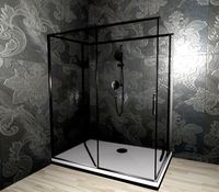
Shower drain by Fickert
...can be scaled as well to fit your shower / bath tub drain without issues. i checked sizes for scaling with common pipe diameters.
thingiverse
free

Hpperlow CG Power Wire Retainer by Fickert
...ingiverse
a quick print to keep the power wires retained on any 30 x 30mm screw pattern. specific to the hyperlow series frames.
thingiverse
free

Pixhawk 2.1 mounting Template by Fickert
...eated this model for you guys to print. it has the cube centered with the four inner holes, and has the drilling portions marked.
thingiverse
free

Folger Tech FT-5 Spool Mount for 25mm Carbon Fiber Tube by Fickert
...r tube by fickert
thingiverse
this is for a requested size upgrade for some spare carbon fiber tubes someone asked for.
cheers!
thingiverse
free
Panel Due 7in TFT mount Rev1 by Fickert
... or tomorrow for ease of use with anyone's printer. this is meant to be mounted in the corner of two extrusions (right side).
thingiverse
free

Ummagawd Remix TBS Unify / RDQ Mach 2 VTX Pigtail Mount by Fickert
...for vtxs that use the t style pigtail. works great and very sturdy. no supports needed. recommend abs or petg; a sturdy material.
thingiverse
free

Magpul M Lok Rail Cover Insert for Loose Rail Covers by Fickert
...to spec. these are designed to account for the additional room. these may not work for you without modification. best of luck! :)
thingiverse
free

Pixhawk Safety Switch Mount by Fickert
... flat: this is the same design to hide the screw threads, but with a flat bottom. easier to print for most and should do the job.
thingiverse
free

ScottyBoard Teesnys LED Drive PCB Case by Fickert
...e currently. if the smaller 10uf can fit without interference please let me know and i will remove the circular hole for the cap.
thingiverse
free

Glass Fasteners for print Bed (Designed for FT-5) by Fickert
...versions. use 100 percent infill to ensure strength.
you will also need 8x m3 nuts to use to mount like in the pictures provided.
8In
turbosquid
$5

8in Pipe
... available on turbo squid, the world's leading provider of digital 3d models for visualization, films, television, and games.
turbosquid
$2

3/8in Pipe
... available on turbo squid, the world's leading provider of digital 3d models for visualization, films, television, and games.
turbosquid
$2

1/8in Pipe
... available on turbo squid, the world's leading provider of digital 3d models for visualization, films, television, and games.
3ddd
$1

VINTAGE LEVER-HANDLE 8in WIDESPREAD FAUCET SET
...set
3ddd
restoration hardware , смеситель
vintage lever-handle 8in widespread faucet set
turbosquid
$10

Pipes 4in x 8in Eccentric Reducer
... available on turbo squid, the world's leading provider of digital 3d models for visualization, films, television, and games.
turbosquid
$10

Pipes 4in x 8in Concentric Reducer
... available on turbo squid, the world's leading provider of digital 3d models for visualization, films, television, and games.
turbosquid
$16

RH SUTTON CROSS-HANDLE 8in WIDESPREAD FAUCET
... 8in widespread faucet for download as 3ds, max, obj, and fbx on turbosquid: 3d models for games, architecture, videos. (1156637)
turbosquid
$10

Pipes 4in x 8in Short Radius Reducing Bend
... available on turbo squid, the world's leading provider of digital 3d models for visualization, films, television, and games.
turbosquid
$10

Pipes 4in x 8in Long Radius Reducing Bend
... available on turbo squid, the world's leading provider of digital 3d models for visualization, films, television, and games.
3ddd
$1

Vintage 8in Widespread Faucet Set
... -http://www.restorationhardware.com -
модель: vintage 8" widespread faucet set
размеры: w-270mm, d-200mm, h-180mm
Braces
archive3d
free
Bracing 3D Model
...
holder bracing strengthening
bracing 4 - 3d model (*.gsm+*.3ds) for interior 3d visualization.
archive3d
free
Bracing 3D Model
...
bracing strengthening holder
bracing 2 - 3d model (*.gsm+*.3ds) for interior 3d visualization.
turbosquid
$5

brace PARIS
...osquid
royalty free 3d model brace paris for download as max on turbosquid: 3d models for games, architecture, videos. (1284415)
archive3d
free
Bracing 3D Model
...older fastening strengthening
bracing 1 - 3d model (*.gsm+*.3ds) for interior 3d visualization.
archive3d
free
Bracing 3D Model
...older fastening strengthening
bracing 3 - 3d model (*.gsm+*.3ds) for interior 3d visualization.
turbosquid
$20
Corner Brace Bracket
...oyalty free 3d model corner brace bracket for download as stl on turbosquid: 3d models for games, architecture, videos. (1322777)
turbosquid
$10

Craftsman Handtools - Brace
... available on turbo squid, the world's leading provider of digital 3d models for visualization, films, television, and games.
turbosquid
$2
Degree Brace 4
...el degree brace 4 for download as 3ds, max, obj, c4d, and fbx on turbosquid: 3d models for games, architecture, videos. (1205705)
turbosquid
$1
Degree Brace 3
...el degree brace 3 for download as 3ds, max, obj, c4d, and fbx on turbosquid: 3d models for games, architecture, videos. (1205719)
turbosquid
$1
Degree Brace 2
...el degree brace 2 for download as 3ds, max, obj, c4d, and fbx on turbosquid: 3d models for games, architecture, videos. (1205714)
Ft
3ddd
free
Renault FT-17
...renault ft-17
3ddd
ft-17 , renault , танк
turbosquid
$85

40 ft container
...id
royalty free 3d model 40 ft container for download as max on turbosquid: 3d models for games, architecture, videos. (1154866)
turbosquid
$45
container 40 ft
...id
royalty free 3d model container 40 ft for download as max on turbosquid: 3d models for games, architecture, videos. (1480343)
turbosquid
$85
Renault FT-17
...yalty free 3d model renault ft-17 for download as 3ds and max on turbosquid: 3d models for games, architecture, videos. (1145251)
turbosquid
$5

NVidia FT 03
... 3d model nvidia ft 03 for download as 3ds, max, obj, and fbx on turbosquid: 3d models for games, architecture, videos. (1233064)
turbosquid
$25

Container 20 ft
...l container 20 ft for download as 3ds, max, obj, fbx, and upk on turbosquid: 3d models for games, architecture, videos. (1384306)
turbosquid
$25
FT Buck Saw
... available on turbo squid, the world's leading provider of digital 3d models for visualization, films, television, and games.
3ddd
free
Jaga - Maxi FT-10
... om
радиатор jaga - maxi ft-10
width: 63 cm
depth: 13 cm
height: 59 cm
сайт производителя:http://www.jaga.be/
turbosquid
$45

20 ft container
...ontainer for download as blend, blend, dae, fbx, obj, and stl on turbosquid: 3d models for games, architecture, videos. (1516815)
turbosquid
$35

Yaesu FT-897D Transceiver
...y free 3d model yaesu ft-897d transceiver for download as max on turbosquid: 3d models for games, architecture, videos. (1160274)
Acrylic
turbosquid
$15
Acrylic Lectern For The Chruch - Podium Acrylic
...the chruch - podium acrylic for download as skp, obj, and 3ds on turbosquid: 3d models for games, architecture, videos. (1642137)
3ddd
free
Acrylic bathtub
...acrylic bathtub
3ddd
ванна
acrylic bathtub. size 170x110 cm
turbosquid
$24
Acrylic Stool
...3d model acrylic stool for download as 3ds, max, obj, and fbx on turbosquid: 3d models for games, architecture, videos. (1311388)
turbosquid
$9
Acrylic Tables
... available on turbo squid, the world's leading provider of digital 3d models for visualization, films, television, and games.
turbosquid
$9
Acrylic Chair
... available on turbo squid, the world's leading provider of digital 3d models for visualization, films, television, and games.
turbosquid
$5

Acrylic Chair
... available on turbo squid, the world's leading provider of digital 3d models for visualization, films, television, and games.
turbosquid
$3

Table acrylic
... available on turbo squid, the world's leading provider of digital 3d models for visualization, films, television, and games.
3d_export
$5
Acrylic bath
... empire. originally created in 3ds max 2021 and v-ray next. materials v-ray mtl rubber; chromium; acrylic. modifiers: turbosmooth
3ddd
$1
Acrylic GM
...acrylic gm
3ddd
вентилятор
model is available in retail fanstar
3d_export
$17

Acrylic Chair 3D Model
...acrylic chair 3d model
3dexport
chair furniture acrylic
acrylic chair 3d model shalasaska 7623 3dexport
Enclosure
3d_export
free
electrical enclosure
...l enclosure where electrical devices like (relays, contactors, busbars ) are kept in order to protect from hazardous environment.
turbosquid
$100

GPU Enclosure
...yalty free 3d model gpu enclosure for download as obj and stl on turbosquid: 3d models for games, architecture, videos. (1381061)
3d_export
$5
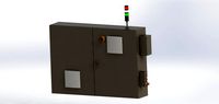
Electrical Enclosure
...ed. also has tower lights attaced on the top.<br>file format that are available:<br>.step<br>.obj<br>.stl
archive3d
free
Enclosure 3D Model
...closure 3d model
archive3d
shower enclosure-acquarius- 3d model for interior 3d visualization.
archive3d
free
Enclosure 3D Model
...enclosure 3d model
archive3d
shower enclosure-omega- 3d model for interior 3d visualization.
archive3d
free
Enclosure 3D Model
...enclosure 3d model
archive3d
shower enclosure-vega - 3d model for interior 3d visualization.
archive3d
free
Enclosure 3D Model
...enclosure 3d model
archive3d
shower enclosure-zenith - 3d model for interior 3d visualization.
turbosquid
$20
shower enclosure
... available on turbo squid, the world's leading provider of digital 3d models for visualization, films, television, and games.
turbosquid
$14
Dumpster Enclosure
... available on turbo squid, the world's leading provider of digital 3d models for visualization, films, television, and games.
turbosquid
$25
3d printer enclosure
... model 3d printer enclosure for download as ipt, skp, and fbx on turbosquid: 3d models for games, architecture, videos. (1634310)
5
turbosquid
$6

Rock 5-5
...urbosquid
royalty free 3d model rock 5-5 for download as obj on turbosquid: 3d models for games, architecture, videos. (1639063)
3d_export
$5
hinge 5
...hinge 5
3dexport
hinge 5
turbosquid
$10
A-5
... available on turbo squid, the world's leading provider of digital 3d models for visualization, films, television, and games.
turbosquid
$2
A-5
... available on turbo squid, the world's leading provider of digital 3d models for visualization, films, television, and games.
turbosquid
$12

Calligraphic Digit 5 Number 5
...hic digit 5 number 5 for download as max, obj, fbx, and blend on turbosquid: 3d models for games, architecture, videos. (1389333)
3ddd
$1

5 роз
...5 роз
3ddd
5 роз в стеклянной вазе
design_connected
$11

iPhone 5
...iphone 5
designconnected
apple iphone 5 computer generated 3d model.
3ddd
$1
Lola 5
...lola 5
3ddd
miniforms
lola 5 miniforms 300*65*134
3ddd
$1

Nexus 5
...dd
nexus , phone , телефон
google nexus 5 phone
3d_ocean
$15

iPhone 5
...iphone 5
3docean
3d 4d apple cinema iphone model modeling phone screen texture
iphone 5 3d model and texture realistic iphone 5.
1
turbosquid
$69
armchairs(1)(1)
... available on turbo squid, the world's leading provider of digital 3d models for visualization, films, television, and games.
turbosquid
$15
ring 1+1
... available on turbo squid, the world's leading provider of digital 3d models for visualization, films, television, and games.
turbosquid
$10

chair(1)(1)
... available on turbo squid, the world's leading provider of digital 3d models for visualization, films, television, and games.
turbosquid
$8

Chair(1)(1)
... available on turbo squid, the world's leading provider of digital 3d models for visualization, films, television, and games.
turbosquid
$2

RING 1(1)
... available on turbo squid, the world's leading provider of digital 3d models for visualization, films, television, and games.
turbosquid
$1
house 1(1)
... available on turbo squid, the world's leading provider of digital 3d models for visualization, films, television, and games.
turbosquid
$1

Table 1(1)
... available on turbo squid, the world's leading provider of digital 3d models for visualization, films, television, and games.
turbosquid
$59

Formula 1(1)
...lty free 3d model formula 1 for download as max, fbx, and obj on turbosquid: 3d models for games, architecture, videos. (1567088)
design_connected
$11
No 1
...no 1
designconnected
sibast no 1 computer generated 3d model. designed by sibast, helge.
turbosquid
$2
desert house(1)(1)
...3d model desert house(1)(1) for download as 3ds, max, and obj on turbosquid: 3d models for games, architecture, videos. (1055095)