Thingiverse

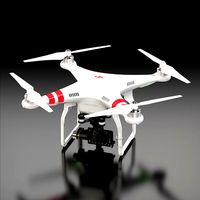
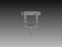
FPV Single Axis Gimbal for ImpulesRC Alien and Similar by Mchaos
by Thingiverse
Last crawled date: 3 years, 1 month ago
03-16-2020 - So I haven't updated this in a while however i have made some changes. I want to post them, but I need to make a video on how to set this up. The new updated frame utilizes bearings. While the original method worked, and did the job, it wasn't ideal. The initial design was an attempt to make this super easy to setup and use. Making the switch to bearings, makes this much better. The gimbal moves so easy and smooth. This new frame still uses the screws that come with the arrow cam, but need to be modified in order to work. Stay tuned..
7-18-2019 - Update. Fixed the STL so that it doesn't print with holes where the stand offs run through. Also added an added another vtx antenna mount for the newer frsky r9mm antenna so you can zip it down.
When I started my first 7" Long Range Build I decided that I wanted some control on the angle of my FPV cam. I felt that because this quad was going to be more about exploration than freestyle that I should be able to have good control at low speeds as well as the ability to fly fast.
Since camera angel dictates speed, the best way to be able to fly slow with control would be to have a low camera angel. To be able to between fast and slow, I had to be able to change the angle in the air.
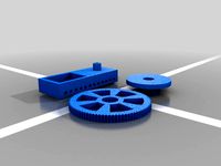
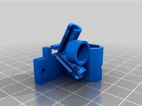
This is what I came up with....
A gimal system that allows you to change your angle mid flight. I have mine set up so that one of the pots on my X7 radio controls the full range of motion. Then I have one of the 3 position switches set up so that all the way back allows control with the pot. one click forward and it goes to my basic flight angle. Easy flight. Not too fast, not too slow. All the way forward send the cam to max angel for turbo fly mode.
I designed this to be held in place by the o-rings, and for there to be no direct connection from the cam to the frame. This is to help reduce vibrations, oscillations and jello.
Video of how it works and set up. https://www.youtube.com/watch?v=GGs2A_NZKms&t=99s
*Currently the Cam adapters are designed to fit Foxeer Arrow "V2" FPV cam.. Because that is what I have. If someone wants to donate the carcass of a Runcam or whatever, I will gladly make mounts for that. I need it to take measurements and make sure of the fit. (Any cam of similar width using the same mounting screws should fit.Screws are important)
*List of adapters for other cams. I will add them as I come up with them. I have no way to test some of these, so they may or may not work.
Foxeer Arrow V2**
Runcam Split / Mini
Generic set
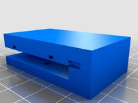
Included are complementary parts for antenna mounting, and VTX Stack mounting also for but not limited to ImpulseRC Alien. I have 2 different VTX antenna mounts. 1 stand alone, and 1 for R9MM receiver.
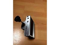
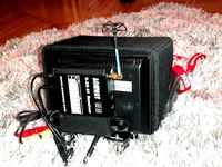
R9MM antenna: I was going to design an antenna holder. I still may, but in the mean time I found one that was really good and I am currently using. It works with the way it was intended to be installed. On the VTX/R9MM mount there is a hole in the base that lines up so that you can run a zip tie through it and hold the antenna holder. 1 single zip tie works great. I have uploaded a pic of how it get installs.
What it fits:
ImpulseRC Alien& Clone frames. It also fits a lot of other frames of this style due to many frames having the same spacing and height on the frame risers.
Spacing on the front risers needs to be Approx 28mm from center to center. ALSO the distance from the next set of risers behind the front risers needs to be at least 48mm center to center from the front risers. This is to accommodate the servo. Length of the Risers are 35mm.
Riser spacing Center to Center.
Width: 28mm
From second set: 48mm
Height: 35mm
YOU WILL NEED:
Micro Servo.
Rubber O-Rings X2; OD: 9mm, ID: 3.5mm Width: 2.5mm.
Foxeer Arrow FPV cam.
Ball Joint x2 (I use Associated because that what I have.
Ball Joint Cups x2 (again.. associate. Must cut the neck shorter on the cups. Completed length of ball joint assembly, 20mm from outside to outside.)
Ball joint rod (Yes associate... you know why.)
Link to suitable oring... https://www.ebay.com/p/Toogoor-50-Pcs-Flexible-Nitrile-Rubber-O-Rings-Washers-Grommets-4mm-X-9mm-X/710187450?iid=261969164068&chn=ps
Gimbal Assembly:
After printing, clean away any stringy's especially from out of the o-ring sockets. Remove the support material from the Frame where the servo goes.
Press insert the o-rings into the o-ring sockets located on the inside left and right walls of the gimbal frame.
use a small amount of white lithium grease and lightly grease the exposed surface of the oring.
Install ball joint into end of the arm of the Horn adapter. it should face out the opposite side of the recess that goes on the cam.
install horn adapter(the one you just put the ball joint on) on the left side of the camera. It will be a snug fit. Push it on, and screw it in with the screws that came with the camera. Make sure the arm is as far up as possible. the ball joint should be facing away from the cam its self. Snug it down so it does not move.
Install the other adapter that printed with the horn on the right side of the cam. Again it will be a snug fit. Snug it down with the screws that came with the cam.
It is important to use the supplied screws that came with the cam. It is the truss shape of the head that keeps the came in place against the o-rings. This is another reason this may not fit another cam.
lightly spread the Left and Right frame walls apart and slide the camera in seating the heads of the screws into the o-rings. It should fit snug enough to keep the camera in but still allow it to pivot.
Install the servo in the back of the gimbal frame with the servo spur towards the bottom. Use the supplied screws that came with the servo to mount it in place.
Take one of the supplied servo horns that came with the servo and widen the hole in the second to last hole from the end of the horn to accept a ball joint to be threaded in.
Thread ball joint into servo horn. Be careful not to break the servo horn.
Assemble linkage. Take the 2 ball joint cups and cut about 1/4 of an inch from the portion that the rod threads into. Take the threaded rod and cut it about 1/2" maybe less. The 2 ball cups should thread together all the way leaving no rod exposed. The length should be about 20mm from end to end. It just need to be close.
Carefully snap the ball joint cup of the linage onto the ball joint on the cam horn. and again with the other end of the linkage to the ball joint on the servo horn.
(Assuming you have set up the servo in your FC firmware and on your transmitter) Rotate the servo all the way clockwise. Move the cam all the way down. Then press the horn onto the servo spur. This should get you very close to where it should be.
adjust settings to accommodate full range of motion.
Install onto frame. Just slide it onto the front risers. Be aware of servo cable. Make sure it is routed the correct way.
***when installing the top plate, make sure to tighten the screws in the front to the risers that the gimbal frame slide over very snug. The frame is designed to be a hair higher than the risers to create a snug fit.
***VIDEO COMING OF ASSEMBLY AND INSTALL
7-18-2019 - Update. Fixed the STL so that it doesn't print with holes where the stand offs run through. Also added an added another vtx antenna mount for the newer frsky r9mm antenna so you can zip it down.
When I started my first 7" Long Range Build I decided that I wanted some control on the angle of my FPV cam. I felt that because this quad was going to be more about exploration than freestyle that I should be able to have good control at low speeds as well as the ability to fly fast.
Since camera angel dictates speed, the best way to be able to fly slow with control would be to have a low camera angel. To be able to between fast and slow, I had to be able to change the angle in the air.
This is what I came up with....
A gimal system that allows you to change your angle mid flight. I have mine set up so that one of the pots on my X7 radio controls the full range of motion. Then I have one of the 3 position switches set up so that all the way back allows control with the pot. one click forward and it goes to my basic flight angle. Easy flight. Not too fast, not too slow. All the way forward send the cam to max angel for turbo fly mode.
I designed this to be held in place by the o-rings, and for there to be no direct connection from the cam to the frame. This is to help reduce vibrations, oscillations and jello.
Video of how it works and set up. https://www.youtube.com/watch?v=GGs2A_NZKms&t=99s
*Currently the Cam adapters are designed to fit Foxeer Arrow "V2" FPV cam.. Because that is what I have. If someone wants to donate the carcass of a Runcam or whatever, I will gladly make mounts for that. I need it to take measurements and make sure of the fit. (Any cam of similar width using the same mounting screws should fit.Screws are important)
*List of adapters for other cams. I will add them as I come up with them. I have no way to test some of these, so they may or may not work.
Foxeer Arrow V2**
Runcam Split / Mini
Generic set
Included are complementary parts for antenna mounting, and VTX Stack mounting also for but not limited to ImpulseRC Alien. I have 2 different VTX antenna mounts. 1 stand alone, and 1 for R9MM receiver.
R9MM antenna: I was going to design an antenna holder. I still may, but in the mean time I found one that was really good and I am currently using. It works with the way it was intended to be installed. On the VTX/R9MM mount there is a hole in the base that lines up so that you can run a zip tie through it and hold the antenna holder. 1 single zip tie works great. I have uploaded a pic of how it get installs.
What it fits:
ImpulseRC Alien& Clone frames. It also fits a lot of other frames of this style due to many frames having the same spacing and height on the frame risers.
Spacing on the front risers needs to be Approx 28mm from center to center. ALSO the distance from the next set of risers behind the front risers needs to be at least 48mm center to center from the front risers. This is to accommodate the servo. Length of the Risers are 35mm.
Riser spacing Center to Center.
Width: 28mm
From second set: 48mm
Height: 35mm
YOU WILL NEED:
Micro Servo.
Rubber O-Rings X2; OD: 9mm, ID: 3.5mm Width: 2.5mm.
Foxeer Arrow FPV cam.
Ball Joint x2 (I use Associated because that what I have.
Ball Joint Cups x2 (again.. associate. Must cut the neck shorter on the cups. Completed length of ball joint assembly, 20mm from outside to outside.)
Ball joint rod (Yes associate... you know why.)
Link to suitable oring... https://www.ebay.com/p/Toogoor-50-Pcs-Flexible-Nitrile-Rubber-O-Rings-Washers-Grommets-4mm-X-9mm-X/710187450?iid=261969164068&chn=ps
Gimbal Assembly:
After printing, clean away any stringy's especially from out of the o-ring sockets. Remove the support material from the Frame where the servo goes.
Press insert the o-rings into the o-ring sockets located on the inside left and right walls of the gimbal frame.
use a small amount of white lithium grease and lightly grease the exposed surface of the oring.
Install ball joint into end of the arm of the Horn adapter. it should face out the opposite side of the recess that goes on the cam.
install horn adapter(the one you just put the ball joint on) on the left side of the camera. It will be a snug fit. Push it on, and screw it in with the screws that came with the camera. Make sure the arm is as far up as possible. the ball joint should be facing away from the cam its self. Snug it down so it does not move.
Install the other adapter that printed with the horn on the right side of the cam. Again it will be a snug fit. Snug it down with the screws that came with the cam.
It is important to use the supplied screws that came with the cam. It is the truss shape of the head that keeps the came in place against the o-rings. This is another reason this may not fit another cam.
lightly spread the Left and Right frame walls apart and slide the camera in seating the heads of the screws into the o-rings. It should fit snug enough to keep the camera in but still allow it to pivot.
Install the servo in the back of the gimbal frame with the servo spur towards the bottom. Use the supplied screws that came with the servo to mount it in place.
Take one of the supplied servo horns that came with the servo and widen the hole in the second to last hole from the end of the horn to accept a ball joint to be threaded in.
Thread ball joint into servo horn. Be careful not to break the servo horn.
Assemble linkage. Take the 2 ball joint cups and cut about 1/4 of an inch from the portion that the rod threads into. Take the threaded rod and cut it about 1/2" maybe less. The 2 ball cups should thread together all the way leaving no rod exposed. The length should be about 20mm from end to end. It just need to be close.
Carefully snap the ball joint cup of the linage onto the ball joint on the cam horn. and again with the other end of the linkage to the ball joint on the servo horn.
(Assuming you have set up the servo in your FC firmware and on your transmitter) Rotate the servo all the way clockwise. Move the cam all the way down. Then press the horn onto the servo spur. This should get you very close to where it should be.
adjust settings to accommodate full range of motion.
Install onto frame. Just slide it onto the front risers. Be aware of servo cable. Make sure it is routed the correct way.
***when installing the top plate, make sure to tighten the screws in the front to the risers that the gimbal frame slide over very snug. The frame is designed to be a hair higher than the risers to create a snug fit.
***VIDEO COMING OF ASSEMBLY AND INSTALL
Similar models
thingiverse
free

simple pos fatshark pan by sircrashalot
...hingiverse
fits on 9g servo , no splines, should just fit snug with horn mounting screw. it could be better, but it works for me
thingiverse
free

QAV250 32mm board camera piitch gimbal mount by adamky
...lumenier sells: http://www.getfpv.com/ultra-light-plastic-lumenier-camera-case.html.
https://www.youtube.com/watch?v=-rmjgkurony
thingiverse
free
Servo Horn Extension by MateusOP
... i did not designed the servo attachment, you gave to glue it into an original servo horn. this is the way i needed to create it.
thingiverse
free

pan tilt remix uses ES08MA 9g servos by Thesquirlmaster
...res.
this thing printed in pla with my settings weighs in at 60 grams.
this is a remix of http://www.thingiverse.com/thing:107957
thingiverse
free

Minimalist FPV Pan/tilt
...you have. i had to fit my camera upside down, but this is not a problem for me because i use an fpv monitor that i can turn over.
thingiverse
free

Wrist Gear for standard servo mount for Inmoov rotating wrist by magicaltrevor
...the servo cap. it might be a little tall so you can shave some of the bottom off. i'll probably make a cleaner version later.
thingiverse
free

DJI F450 2-Axis Gimbal for Sony Action Cam by SuperBearFur
...ction cam. the base mounts to the f450 using zip ties. the gimbal could be smoother if i used brushless motors instead of servos.
thingiverse
free

Vtx and Rx Antenna mounts by Zamjustice
...tice
thingiverse
needed to isolate the vtx pigtail from the frame, so came up with this. also required a fixed rx antenna mount.
thingiverse
free

Arducam OV5647 Case for Ender 3 Cam Boom by ardichoke
...se of remixing. i'm not sure how consistent the tolerances on these cams are, and i only have one so it was designed to that.
thingiverse
free

Linear antenna standoff mount by tundraking
...cale your print down a percent or two in the slicer and print again.
then just slide the antenna over any standoff on your drone.
Mchaos
thingiverse
free

Precision spinner thingy test toy??? by Mchaos
...precision spinner thingy test toy??? by mchaos
thingiverse
this is something i designed to test my printer...
thingiverse
free

Dino Toys 2 by Mchaos
...ht this would be a neat quick print for the kids.. so i flipped the legs so they were correct. it came out good. my son loved it.
thingiverse
free

30mm Honeycomb Fan Grill by Mchaos
...
i like the honeycomb fan grills, but i couldn't find one that ws 30mm to fit my v6 j-head hot end , so i remixed this one .
thingiverse
free

30 & 40 mm Concave honeycomb fan grill. by Mchaos
...; 40 mm concave honeycomb fan grill. by mchaos
thingiverse
i just thought this looked cool. its concave and honeycomb.. enjoy...
thingiverse
free

Igus Drylin bearing holder by Mchaos
... size not currently correct.. i am trying to find the right tightness...
i have uploaded a version 2 which is more streamlined...
thingiverse
free

Spool Roller by Mchaos
...nd are 15.5mm outside diameter.
bearings are also press fit so you don't have to print the caps if you don't want too...
thingiverse
free

Custom Bowden Carriage w/ dual LED's by Mchaos
...towards what i want because i cannot find any out there like this.
this is a work in progress.
added an adjustable sensor mount.
thingiverse
free

FPV GPS mount UBLOX MINI 8 by Mchaos
...#39;s designed so that you can lock a cover on it to keep the gps in place. similarly it has notches for a zip tie if you prefer.
thingiverse
free

Single and No fan case cover for Daltoncnc's Ramps case by Mchaos
...is, but didn't want the fet fans.
so i remixed it to have only a single fan, or no fan at all.
i also took of the ramps logo.
thingiverse
free

Geared Boweden Extruder (Flexable Filament Capable) by Mchaos
... it in.
i also put a cutout in so when the set screw is aligned with it, you can easily get a tool in to tighten it.
i like it...
Gimbal
turbosquid
$1
Yuneec Save Stick for Gimbal
... available on turbo squid, the world's leading provider of digital 3d models for visualization, films, television, and games.
3d_export
$20
splashdrone gimbal camera
...nsions. all textures used have been included. thank you for purchasing this model!! click on my username to see more of my models
3d_export
$40
splashdrone 3 plus with gimbal camera
...nsions. all textures used have been included. thank you for purchasing this model!! click on my username to see more of my models
turbosquid
$88
DJI Phantom 2 Quadcopter with gimbal for GoPro HERO4 or 3
... available on turbo squid, the world's leading provider of digital 3d models for visualization, films, television, and games.
3d_export
$5

concentrate box
...concentrate box 3dexport concealer box with handle and gimbal ...
cg_studio
$55
Drone Quadrocopter With Camera Rigged3d model
...fly wing propeller rc video camera sky dron spy gimbal gopro riged aircraft toy .obj .fbx .max .3ds -...
3d_ocean
$29
Drone Quadrocopter With Camera Rigged
...quadrocopter with camera rigged 3docean aircraft camera dron fly gimbal gopro propeller quadrocopter rc riged sky sport spy toy...
3ddd
free
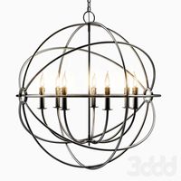
Foucault's Iron Orb
...physicist léon foucault's gyroscope inspired our openwork globe. its double-gimbal frame is built of iron around a nucleus of...
thingiverse
free
Gimbal by tannermichael
...amera and gravity to self level. the gimbal uses .125" axles to pivot on. this gimbal was made using autodesk inventor 2015.
thingiverse
free

2020 Gimbal
...2020 gimbal
thingiverse
2020 gimbal
Fpv
turbosquid
$1

FPV VTX Antenna
...e 3d model fpv vtx antenna for download as obj, fbx, and stl on turbosquid: 3d models for games, architecture, videos. (1230317)
3d_export
$9

Fpv logo 3D Model
...onogram vehicle part of auto transport 3d model logo emblem detailed high quality badge
fpv logo 3d model rmodeler 59628 3dexport
3d_export
$8
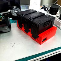
dji fpv battery slot holder
...er for 3 dji fpv batteries. holds perfectly without shaking. need 1 m3 countersunk head bolt. need to print 6 pin, 1 case, 1 cap.
3d_export
$10
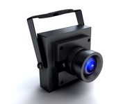
fpv camera hd 700tvl
...aterials are logically named<br>the main format is in 3ds max 2009.<br>satisfcation garranteed..<br>thank you !
thingiverse
free
FpV Mount (SOPORTE FPV) by elborjas1987
...fpv mount (soporte fpv) by elborjas1987
thingiverse
this is a fpv mount with the same holes of naza base.
thingiverse
free
fpv by tbutera
...fpv by tbutera
thingiverse
fpv
thingiverse
free
fpv by tbutera
...fpv by tbutera
thingiverse
fpv
thingiverse
free
FPV DRONE ROOSTER DJI FPV PART
...fpv drone rooster dji fpv part
thingiverse
fpv drone rooster dji fpv install part
thingiverse
free
FPV monitor
...tml?rmmds=myorder&cur_warehouse=cn
link for download : https://cults3d.com/fr/mod%c3%a8le-3d/divers/fpv-monitor-ecran-fpv-faf
thingiverse
free
FPV receiver mount for FPV display by petrex
...eceiver mount for fpv display by petrex
thingiverse
aomway receiver mount for field view 777 fpv monitor. with small cable tray.
Alien
3d_export
$15

alien
...alien
3dexport
alien
3d_export
free

alien
...alien
3dexport
alien
3d_export
$19

Alien Mountains glacier peaks alien mountains alien landscapes
...untains alien landscapes
3dexport
1.alien mountains glacier peaks alien mountains alien landscapes 2.files include 3dmax fbx obj
3d_ocean
$8

Alien
...ocean
alien character game green lowpoly space ufo weird wild
3d model of alien, optimized for high poly model 1350 total polygon
3d_export
$5

alien
...alien
3dexport
the model of the alien is executed in the program max version 2020. the model has a skeleton.
3d_ocean
$8
3d alien
...3d alien
3docean
3d alien 3d model alien
3d model alien, make by lightwave software
turbosquid
$12

Alien Mountains glacier peaks alien mountains alien landscapes
... peaks alien mountains alien landscapes for download as max on turbosquid: 3d models for games, architecture, videos. (1621520)
turbosquid
$5

Alien
...lien
turbosquid
royalty free 3d model alien for download as on turbosquid: 3d models for games, architecture, videos. (1234719)
turbosquid
$2
Alien
...lien
turbosquid
royalty free 3d model alien for download as on turbosquid: 3d models for games, architecture, videos. (1544698)
3d_export
$14

ben 10 alien force alien-x
...ben 10 alien force alien-x
3dexport
a 3d model of ben 10 alien force alien, alien-x. with turn table animation.
Similar
3d_export
$20

sports car similar to a chevrolet
...sports car similar to a chevrolet
3dexport
a sports car similar to a chevrolet. high-poly and low-poly models
turbosquid
$10

2 Similar Cutlery Sets
...odel 2 similar cutlery sets for download as c4d, c4d, and fbx on turbosquid: 3d models for games, architecture, videos. (1609168)
turbosquid
$49

Gun similar to Colt Peacemaker
... available on turbo squid, the world's leading provider of digital 3d models for visualization, films, television, and games.
turbosquid
$49

Gun similar to Jericho 941
... available on turbo squid, the world's leading provider of digital 3d models for visualization, films, television, and games.
turbosquid
free

Gun similar to Colt 1911
... available on turbo squid, the world's leading provider of digital 3d models for visualization, films, television, and games.
3d_export
$20

The girl similar to Mandy 3D Model
...autiful sexy
the girl similar to mandy 3d model download .c4d .max .obj .fbx .ma .lwo .3ds .3dm .stl iasha3d39286 103194 3dexport
3d_export
$10
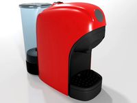
coffee machine similar lavazza tiny
...commended for photorealistic rendering of domestic environments, the model is in real scale and has dimensions of 29.6x11xh 25 cm
turbosquid
$49

Gun similar to Desert Eagle .44 Magnum
... available on turbo squid, the world's leading provider of digital 3d models for visualization, films, television, and games.
3ddd
$1

The girl similar to Mandy
...real-world scale and is centered at 0,0,0.
objects, materials, textures use meaningful names.
mapping is only overlapping in hair
turbosquid
$35
Ground Surveillance Drone (Similar to Tom Clancy's Rainbow Six: Siege drone)
...om clancy's rainbow six: siege drone) for download as c4d on turbosquid: 3d models for games, architecture, videos. (1341540)
Axis
3ddd
$1

Мария Axis
...
3ddd
кухня , классическая , axis
модель кухни.
3d_export
$22
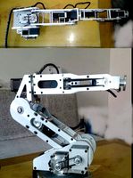
Axis robot 6-axis robotic arm
...ing parts drawings, standard parts purchased parts list, can be produced directly according to the drawings, welcome to download!
3ddd
free

Versatile Axis
...ddd
nexus , плитка
http://bvtileandstone.com/ceramic-porcelain/versatile-axis/
3d_export
$19
robot 2 axis
...robot 2 axis
3dexport
robot 2 axis
turbosquid
$40
Axis R5F
... available on turbo squid, the world's leading provider of digital 3d models for visualization, films, television, and games.
turbosquid
$40
Axis S5F
... available on turbo squid, the world's leading provider of digital 3d models for visualization, films, television, and games.
turbosquid
$30

Axis Athlon
... available on turbo squid, the world's leading provider of digital 3d models for visualization, films, television, and games.
turbosquid
$10

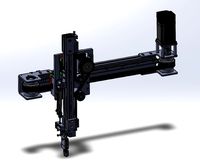
Linear Axis
... available on turbo squid, the world's leading provider of digital 3d models for visualization, films, television, and games.
3d_export
$15

drawing axis
...drawing axis
3dexport
simple rendering of the scene file
3ddd
$1
versatile axis ARC
...versatile axis arc
3ddd
versatile , плитка
versatile axis arc red dot design award
Single
3d_export
$5

single sofa single chair
...single sofa single chair
3dexport
single sofa single chair 3d model
3d_export
$5

single sofa single chair
...single sofa single chair
3dexport
single sofa single chair 3d model
3d_export
$5

single fastener
...single fastener
3dexport
single fastener
3ddd
$1
Single FLOU
... sofa , трансформер
диван-трансформер single от итальянского производителя flou
3ddd
$1
bed single
...bed single
3ddd
постельное белье
bed single 190cm*90cm
3ddd
$1

Single Flou
...single flou
3ddd
качественная моделька дивана-трансформера single flou.
3d_ocean
$9
Single sofa
...le sofa
3docean
modern sofa single sofa sofa white sofa.comfortable sofa
single sofa,sofa,modern sofa,white sofa.comfortable sofa
3d_export
free

Single Knife
...single knife
3dexport
a single knife, presumably it was used as one of the throwing knives.
3d_export
free

couch - single
...couch - single
3dexport
low poly single couch with .psd file for personal customization
3d_ocean
$5
Single Sofa
...single sofa
3docean
single sofa made by fabric , wood frame & ss leg