Thingiverse
Ford Flex Lane-Keeping Assist / Auto-Highbeam Adapter by XirallicBolts
by Thingiverse
Last crawled date: 2 years, 9 months ago
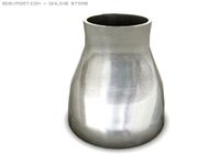
Adapter to fit Ford's twist-attach rearview mirrors to 2013-2019 Ford Flex to add Lane Departure Warning (LDW), Lane Keeping Assistance (LKA), and Automatic High-Beams (AHB). Capitalized italics indicate the name of a printed part ("Visual Guide", "Vinyl Template"). "Mirror Body" refers to the aluminum structure between the mirror and the camera.
Parts needed:
Rearview mirror from a 2013-2019 Ford Explorer, Ford Taurus, Lincoln MKS, or Lincoln MKT. Searching on eBay for MKS / MKT mirrors, selecting Used condition, usually brings up results for less than $100. Some sellers list AHB-only mirrors as LKA -- verify the mirror has a 1cm circular camera lens on the front or AHBC/LA in the plastic! Mirrors from the Fusion/Escape/etc look very similar but the body is longer and will not work with this design.
M4 heat-set insert nuts - print was designed around M4 x 12mm x 6mm
M4 screws, around 25mm-30mm long, qty 5
Aluminum sheet, 1/8" (3mm) thick.
6-32 x 3/4" screws, qty 3
JB Weld (or similar epoxy)
Oracal 651 Permanent Vinyl, Matte Black
Wire suitable for automotive use, 18awg or so.
Tactile pushbutton, momentary contact, 6mm or so length
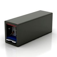
Molex Connectors are a good idea to make connections. At least 4 pins are required. This isn't necessary if the mirror you purchase included a cut section of the wires from the headliner.
Tools Needed
Metalworking tools to cut/grind/drill aluminum sheet
Soldering supplies
Scalpel with extra blades
Laser level helps but is not required
Alternative method being researched: With access to a CNC, it may be possible to form the entire adapter out of aluminum rather than cutting/grinding the aluminum sheet.
It may also be possible to have an online service (such as OSH Cut) cut the aluminum design as well.
T10 / T15 / T20 driver, whatever size the camera is held on with.
FORscan USB adapter cable. OBDLink EX is best but the $15 generics will work as well.
Printed Parts
Metal Template -- Used as a guide for cutting the aluminum sheet.
Vinyl Template -- Used as a guide for aligning the main adapter, as well as trimming the vinyl. Hole in the middle is for the factory mirror mount.
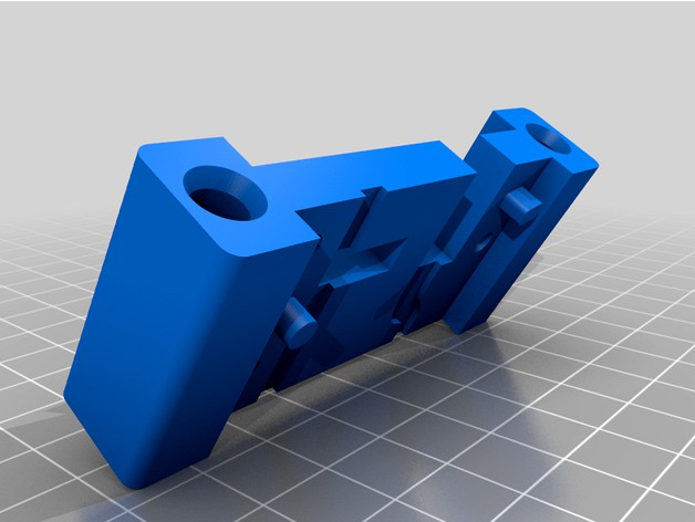
Windshield Adapter -- The main body for adapting the mirror's position/angle. 6+ walls, 50%+ infill, supports as needed. This needs to be very strong and resistant to deformation in direct sunlight.
Camera Spacer -- Used to support Visual Guide and move the camera closer to the windshield. 5+ walls, 50%+ infill, with supports.
Visual Guide -- This will be visible through the windshield. 3+ walls, 20% infill, with supports. Orient with the 'camera' looking upwards (standing on legs), with raft. For better results, print with Cura 'Fuzzy Skin' (TODO: Get settings off main computer)
Lower Cover -- Covers the whole assembly. 2 walls, 20% infill, with supports. For best results, print with same Fuzzy Skin settings as above and orient part so the part closest to the mirror is facing down (90% from how it will install, pointing up).
Upper Cover -- Same as Lower Cover. Print with a raft.
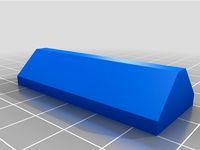
Locking Tab -- Used to keep the mirror from rotating back out. 2+ walls, 20% infill.
Post-Processing
Both Windshield Adapter and Camera Spacer require the heat-set threads pushed in using a soldering iron. Heat-set in the Camera Spacer, plus fuzzy skin on Visual GuideApply some form of tape (such as black Electrical tape or microfiber wire tape) to the edges of Visual Guide that will be touching the glass, to avoid scratching the vinyl.
Metalworking
Using Metal Template, cut a piece of 6061 aluminum, 1/8" (3mm) thick, to match the template. Drill and grind as needed.
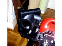
Attach the finished piece to Windshield Adapter using screws of an appropriate length through the heat-set threads.
Test the difficulty of attaching the mirror to this part. You don't want it loose, but also not so tight that you break it off the windshield.Photo of completed part, and as attached to mirror
Prep the mirror - Wiring
The mirror will require a connection to +12v power, ground, and HS-CAN.
On most mirrors, Pin 1 (Violet/Brown) is +12v, Pin 8 (Black) is Ground, Pin 14 (White/Blue) is HS-CAN+, Pin 15 (White) is HS-CAN-, and Pin 10 (Green/Orange) is the Enable/Disable switch.
On my mirror, I carefully removed the plastic trim ring around the glass, removed the internals, and drilled a small hole in the top of the mirror. I soldered one side of the tactile switch to Green/Orange and the other to Black. Then, glued the switch to that hole.
Solder up the molex connector if necessary, giving yourself plenty of wire to wherever you plan on getting power and HS-CAN connection.
Prep the mirror - printed parts
Be careful not to damage the fragile ribbon cable!
Unscrew the camera on the front of the mirror.
Carefully insert the Camera Spacer between the camera and housing.
Screw the camera back in, using longer 6-32 screws. Ensure the camera is flush against the print so alignment wasn't affected. Break off alignment tabs on the print if needed.
Temporarily attach the Visual Guide to the Camera Spacer using the heat-set threads on the bottom. Check that the camera looks centered in the print, modify Visual Guide as needed.
Remove Visual Guide. We'll reinstall it later.
Prep the windshield
Remove your existing rearview mirror. The metal mounting tab can stay on the glass. See my other designs for a tool that may help.
Remove the rain sensor cover, if equipped. There's no clips; pulls straight off.
Thoroughly clean the windshield inside using isopropyl and a nonwoven wipe -- the goal is to have zero dust on the glass when applying vinyl.
Cut two pieces of vinyl using Vinyl Template as a rough guide -- the seam will be at the top of the existing metal tab. Make these pieces 2-3" larger than needed so your fingerprints will be on the part getting trimmed off. Do not cut the trapezoid out.
In as clean of an environment as possible, apply the upper vinyl to the inside of the windshield, followed by the lower vinyl. Start from the top and slowly work your way down, running your finger back and forth to apply as evenly as possible. Do everything within your power to avoid getting dust or bubbles in the portions that won't be trimmed. Use transfer paper if necessary. The vinyl will look uneven from the outside for the first couple hours. As long as there's no dust or bubbles, it should even out.
Once you're satisfied with the vinyl application, tape Vinyl Template to the windshield. As best as possible, use the ceramic dots embedded on the glass to help align Vinyl Template vertically. A high powered flashlight helps. Use as much tape as necessary to keep this piece in place.
Mirror Installation
Cover the dashboard with an old towel in case of drips.
Mix and apply JB Weld epoxy to the assembled Windshield Adapter. Glue this to the windshield, using the Vinyl Template to align it vertically. Hold it in place for at least 5 minutes, then use more tape to hold it overnight.
Use a scalpel to carefully trim the vinyl. Try to stay consistent to avoid misaligned edges. Trim both the trapezoid and outer edge of the template. I trimmed the trapezoid, then applied tape inside the trapezoid so I could remove the tape on the outside without moving the template.If something goes wrong, remove the lower of the two vinyl pieces you applied to the windshield. Replace with a new piece and trim again.Remove Vinyl Template once all cuts are completed. Remove unneeded vinyl from the windshield.
After the Windshield Adapter has fully cured, carefully twist your new rearview mirror onto it, holding the base for stability.Check that your camera is centered in the trapezoid window you cut into the vinyl.
If you're satisfied with alignment, insert the Locking Tab on the passenger side, slid down into the body of the mirror.
Ideally, the mirror should not be able to rotate in either direction and the 'tower' on Windshield Adapter should line up with a visible casting seam in the mirror body. If you glued the Windshield Adapter on crooked, you may need to adjust the aluminum piece or apply tape to the Locking Tab.
With the camera lens centered in the trapezoid, attach Visual Guide again.
Attach the Lower Cover. It should try to clip onto the mirror and squeezes against Camera Spacer.
Check the Lower Cover alignment relative to the vinyl. The vinyl should be relatively even all the way around, extending ~3mm past the Lower Cover in each direction.The gap between the Lower Cover and glass is intentional, to help prevent fogging.
Attach the Upper Cover to the Lower Cover.
Reinstall the rain sensor cover, if equipped.
If you need to remove the Lower Cover, remove the rain sensor cover and Upper Cover. Hold the mirror body as you spread the Lower Cover off the clips on one side, then the other.
Installed Mirror Wiring
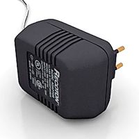
Provide the mirror with 12v Ignition (Switched) power and HS-CAN connection. I used an APIM extension cable behind the radio but these are harder to find in 2021. HS-CAN can be connected to the OBDII port, an Add-a-Fuse can be used for 12v ignition power.
FORscan AsBuilt Changes
You should be familiar with Forscan; I'm not responsible if something goes wrong. Always make a backup of any modules you change. Settings listed belower were relavent to my 2016 Flex 303A (equipped with Adaptive Cruise Control), your needed values may be different.
When connecting for the first time, Forscan will ask if it's a Flex or MKT. You must select MKT -- it will not search for IPMA if you select Flex. If you have a previous saved profile, do not load it, as the saved profile won't have IPMA.IPC
720-01-02 xxxx 6Fxx xx (was 6E) - Enables Auto-Highbeam (?)
720-01-03 xxxx 54xx (was 50) - Enables Lane-Keeping (?)PSCM
730-02-01 xxxx x1xx xxxx (was 0) - Enables Lane-KeepingIPMA
706-01-01 8x00 xxxx xxxx - Driver Assist Enable, Physical lanekeeping switch, No Windshield Heater
706-04-01 C2xx xx8x xx - Enable systems, high sensitivity. The 8 switches to 0 when the lanekeeping button is pressed.
Once everything is ready, find a nice straight road with clear lane markings.
Begin the IPMA Lane Camera calibration procedure in Forscan. Follow the prompts and at 30%, a large dialog will appear on-screen with instructions.
Do not dismiss this dialog. Continue driving in a steady manner, keeping your vehicle centered in the lane, for 10 minutes.
After a few miles you should get lane markings on your left instrument cluster.
Parts needed:
Rearview mirror from a 2013-2019 Ford Explorer, Ford Taurus, Lincoln MKS, or Lincoln MKT. Searching on eBay for MKS / MKT mirrors, selecting Used condition, usually brings up results for less than $100. Some sellers list AHB-only mirrors as LKA -- verify the mirror has a 1cm circular camera lens on the front or AHBC/LA in the plastic! Mirrors from the Fusion/Escape/etc look very similar but the body is longer and will not work with this design.
M4 heat-set insert nuts - print was designed around M4 x 12mm x 6mm
M4 screws, around 25mm-30mm long, qty 5
Aluminum sheet, 1/8" (3mm) thick.
6-32 x 3/4" screws, qty 3
JB Weld (or similar epoxy)
Oracal 651 Permanent Vinyl, Matte Black
Wire suitable for automotive use, 18awg or so.
Tactile pushbutton, momentary contact, 6mm or so length
Molex Connectors are a good idea to make connections. At least 4 pins are required. This isn't necessary if the mirror you purchase included a cut section of the wires from the headliner.
Tools Needed
Metalworking tools to cut/grind/drill aluminum sheet
Soldering supplies
Scalpel with extra blades
Laser level helps but is not required
Alternative method being researched: With access to a CNC, it may be possible to form the entire adapter out of aluminum rather than cutting/grinding the aluminum sheet.
It may also be possible to have an online service (such as OSH Cut) cut the aluminum design as well.
T10 / T15 / T20 driver, whatever size the camera is held on with.
FORscan USB adapter cable. OBDLink EX is best but the $15 generics will work as well.
Printed Parts
Metal Template -- Used as a guide for cutting the aluminum sheet.
Vinyl Template -- Used as a guide for aligning the main adapter, as well as trimming the vinyl. Hole in the middle is for the factory mirror mount.
Windshield Adapter -- The main body for adapting the mirror's position/angle. 6+ walls, 50%+ infill, supports as needed. This needs to be very strong and resistant to deformation in direct sunlight.
Camera Spacer -- Used to support Visual Guide and move the camera closer to the windshield. 5+ walls, 50%+ infill, with supports.
Visual Guide -- This will be visible through the windshield. 3+ walls, 20% infill, with supports. Orient with the 'camera' looking upwards (standing on legs), with raft. For better results, print with Cura 'Fuzzy Skin' (TODO: Get settings off main computer)
Lower Cover -- Covers the whole assembly. 2 walls, 20% infill, with supports. For best results, print with same Fuzzy Skin settings as above and orient part so the part closest to the mirror is facing down (90% from how it will install, pointing up).
Upper Cover -- Same as Lower Cover. Print with a raft.
Locking Tab -- Used to keep the mirror from rotating back out. 2+ walls, 20% infill.
Post-Processing
Both Windshield Adapter and Camera Spacer require the heat-set threads pushed in using a soldering iron. Heat-set in the Camera Spacer, plus fuzzy skin on Visual GuideApply some form of tape (such as black Electrical tape or microfiber wire tape) to the edges of Visual Guide that will be touching the glass, to avoid scratching the vinyl.
Metalworking
Using Metal Template, cut a piece of 6061 aluminum, 1/8" (3mm) thick, to match the template. Drill and grind as needed.
Attach the finished piece to Windshield Adapter using screws of an appropriate length through the heat-set threads.
Test the difficulty of attaching the mirror to this part. You don't want it loose, but also not so tight that you break it off the windshield.Photo of completed part, and as attached to mirror
Prep the mirror - Wiring
The mirror will require a connection to +12v power, ground, and HS-CAN.
On most mirrors, Pin 1 (Violet/Brown) is +12v, Pin 8 (Black) is Ground, Pin 14 (White/Blue) is HS-CAN+, Pin 15 (White) is HS-CAN-, and Pin 10 (Green/Orange) is the Enable/Disable switch.
On my mirror, I carefully removed the plastic trim ring around the glass, removed the internals, and drilled a small hole in the top of the mirror. I soldered one side of the tactile switch to Green/Orange and the other to Black. Then, glued the switch to that hole.
Solder up the molex connector if necessary, giving yourself plenty of wire to wherever you plan on getting power and HS-CAN connection.
Prep the mirror - printed parts
Be careful not to damage the fragile ribbon cable!
Unscrew the camera on the front of the mirror.
Carefully insert the Camera Spacer between the camera and housing.
Screw the camera back in, using longer 6-32 screws. Ensure the camera is flush against the print so alignment wasn't affected. Break off alignment tabs on the print if needed.
Temporarily attach the Visual Guide to the Camera Spacer using the heat-set threads on the bottom. Check that the camera looks centered in the print, modify Visual Guide as needed.
Remove Visual Guide. We'll reinstall it later.
Prep the windshield
Remove your existing rearview mirror. The metal mounting tab can stay on the glass. See my other designs for a tool that may help.
Remove the rain sensor cover, if equipped. There's no clips; pulls straight off.
Thoroughly clean the windshield inside using isopropyl and a nonwoven wipe -- the goal is to have zero dust on the glass when applying vinyl.
Cut two pieces of vinyl using Vinyl Template as a rough guide -- the seam will be at the top of the existing metal tab. Make these pieces 2-3" larger than needed so your fingerprints will be on the part getting trimmed off. Do not cut the trapezoid out.
In as clean of an environment as possible, apply the upper vinyl to the inside of the windshield, followed by the lower vinyl. Start from the top and slowly work your way down, running your finger back and forth to apply as evenly as possible. Do everything within your power to avoid getting dust or bubbles in the portions that won't be trimmed. Use transfer paper if necessary. The vinyl will look uneven from the outside for the first couple hours. As long as there's no dust or bubbles, it should even out.
Once you're satisfied with the vinyl application, tape Vinyl Template to the windshield. As best as possible, use the ceramic dots embedded on the glass to help align Vinyl Template vertically. A high powered flashlight helps. Use as much tape as necessary to keep this piece in place.
Mirror Installation
Cover the dashboard with an old towel in case of drips.
Mix and apply JB Weld epoxy to the assembled Windshield Adapter. Glue this to the windshield, using the Vinyl Template to align it vertically. Hold it in place for at least 5 minutes, then use more tape to hold it overnight.
Use a scalpel to carefully trim the vinyl. Try to stay consistent to avoid misaligned edges. Trim both the trapezoid and outer edge of the template. I trimmed the trapezoid, then applied tape inside the trapezoid so I could remove the tape on the outside without moving the template.If something goes wrong, remove the lower of the two vinyl pieces you applied to the windshield. Replace with a new piece and trim again.Remove Vinyl Template once all cuts are completed. Remove unneeded vinyl from the windshield.
After the Windshield Adapter has fully cured, carefully twist your new rearview mirror onto it, holding the base for stability.Check that your camera is centered in the trapezoid window you cut into the vinyl.
If you're satisfied with alignment, insert the Locking Tab on the passenger side, slid down into the body of the mirror.
Ideally, the mirror should not be able to rotate in either direction and the 'tower' on Windshield Adapter should line up with a visible casting seam in the mirror body. If you glued the Windshield Adapter on crooked, you may need to adjust the aluminum piece or apply tape to the Locking Tab.
With the camera lens centered in the trapezoid, attach Visual Guide again.
Attach the Lower Cover. It should try to clip onto the mirror and squeezes against Camera Spacer.
Check the Lower Cover alignment relative to the vinyl. The vinyl should be relatively even all the way around, extending ~3mm past the Lower Cover in each direction.The gap between the Lower Cover and glass is intentional, to help prevent fogging.
Attach the Upper Cover to the Lower Cover.
Reinstall the rain sensor cover, if equipped.
If you need to remove the Lower Cover, remove the rain sensor cover and Upper Cover. Hold the mirror body as you spread the Lower Cover off the clips on one side, then the other.
Installed Mirror Wiring
Provide the mirror with 12v Ignition (Switched) power and HS-CAN connection. I used an APIM extension cable behind the radio but these are harder to find in 2021. HS-CAN can be connected to the OBDII port, an Add-a-Fuse can be used for 12v ignition power.
FORscan AsBuilt Changes
You should be familiar with Forscan; I'm not responsible if something goes wrong. Always make a backup of any modules you change. Settings listed belower were relavent to my 2016 Flex 303A (equipped with Adaptive Cruise Control), your needed values may be different.
When connecting for the first time, Forscan will ask if it's a Flex or MKT. You must select MKT -- it will not search for IPMA if you select Flex. If you have a previous saved profile, do not load it, as the saved profile won't have IPMA.IPC
720-01-02 xxxx 6Fxx xx (was 6E) - Enables Auto-Highbeam (?)
720-01-03 xxxx 54xx (was 50) - Enables Lane-Keeping (?)PSCM
730-02-01 xxxx x1xx xxxx (was 0) - Enables Lane-KeepingIPMA
706-01-01 8x00 xxxx xxxx - Driver Assist Enable, Physical lanekeeping switch, No Windshield Heater
706-04-01 C2xx xx8x xx - Enable systems, high sensitivity. The 8 switches to 0 when the lanekeeping button is pressed.
Once everything is ready, find a nice straight road with clear lane markings.
Begin the IPMA Lane Camera calibration procedure in Forscan. Follow the prompts and at 30%, a large dialog will appear on-screen with instructions.
Do not dismiss this dialog. Continue driving in a steady manner, keeping your vehicle centered in the lane, for 10 minutes.
After a few miles you should get lane markings on your left instrument cluster.
Similar models
thingiverse
free

Ford Flex Lane-Keeping Assist / Auto-Highbeam Adapter by XirallicBolts
...two holes near the spring clip to 6-32 or similar 9) remove the metal spring clip from the new...
thingiverse
free

BlackVue car dash camera (DR400G) GoPro and rearview mirror mount by xkremator
...ra under rearview mirror - take the "gopro partner" connector from this design:https://www.thingiverse.com/thing:921173
thingiverse
free
Alignment Guides for 3DSourcerer's Universal 3D Printer Enclosure by ane109
...closure must be removed and put back in place frequently.
the guides are sized for use with standard 3/4" double stick tape.
thingiverse
free

Edge Masking Tool by jheising
...ull the masking tool up, finish the curve by hand, then place the masking tool back down using the 2" guide to finish it up.
3dwarehouse
free

8x10 puzzle template
...e as you cut out all the parts. have fun! #diy #hobby #make #plywood #puzzle #saw #scroll #scrollsaw #template #wood #woodworking
3dwarehouse
free
Rearview Car Mirror
...uto dimming and a backup camera. #auto_dimming #automobile #backup #camera #car #display #gray #mirror #part #rearview #tempature
thingiverse
free

Dremel Guide by arc333jd
... easier to install and remove by removing the center of the dremel guide and using a pair of channel locks to compress the tongs.
thingiverse
free
Co2 Laser Mirror 20mm Protective cover by jbase
...cover protects mirrors from dust and dirt.
the cover works for 20mm mirrors and is mounted on m4 rods (bolt tails) using m4 nuts.
thingiverse
free

Removed Trim from Lower Leg of Jesus Mecha Christ by xSlothx
...he leg with the part with the trim facing down, standard supports. use your slicer's mirror function to get the opposite leg.
thingiverse
free

Action Camera Mount for Lotus Elise/Exige by translucent1
...ithout supports (but you will probably have to add some), and one with manual supports included that you trim off after printing.
Xirallicbolts
thingiverse
free

Silverado Popsocket Mount by XirallicBolts
... your phone.
print as-is with supports touching buildplate. after printing, separate or cut where the print slides onto the vent.
thingiverse
free
Milwaukee Packout Screwdriver Organizer by XirallicBolts
...(big -)
7.0mm (small -)
20.3mm (1/2)
17.7mm (7/16)
7.0mm (small +)
15.4mm (3/8)
14.2mm (5/16)
12.3mm (1/4)
thingiverse
free
Ford Flex Lane-Keeping Assist / Auto-Highbeam Adapter by XirallicBolts
...was 0)
when connecting, forscan will ask if you have a flex or mkt. you must select mkt for the rearview mirror (ipma) to appear.
Highbeam
thingiverse
free
Ford Flex Lane-Keeping Assist / Auto-Highbeam Adapter by XirallicBolts
...was 0)
when connecting, forscan will ask if you have a flex or mkt. you must select mkt for the rearview mirror (ipma) to appear.
thingiverse
free

LED Sockel Drehzahlmesser Yamaha XT 250 by 3DMarco
...5mm - grün (neutral) 1 led 5mm - blau (highbeam 1 led 5mm - orange (blinker) 3 passende widerstände...
grabcad
free

Powerfull e-bike headlight with daylight LED
...with daylight led grabcad 50w lensed main light with highbeam controlled by servomotor inside. led daylight looked like eyes...
cg_trader
$5

Marine Spotlight
...they can be 3d printed. light lighting spotlight ledlight highbeam lowbeam marine ship tugboat industry marineservice shipyards freightships containerships...
3dwarehouse
free

Scania R730 Modern Bullbar
..., #bullbar , #bullbars , #lights , #fog , #highbeam ...
Lane
3d_export
$10

Obstacle lane
...obstacle lane
3dexport
obstacle lane
3ddd
$1
Lane Furniture
...niture , журнальный
столик журнальный lane furniture
conrad coffee table текстуры внутри
3ddd
free

Книжный шкаф Lane
...книжный шкаф lane
3ddd
lane , сша
lane furniture возвращаясь до
3ddd
$1
Консоль Lane Furniture
...lane furniture , консоль
консоль lane furniture, сша, текстуры внутри
3ddd
$1

Lane tabouret T1
...lane tabouret t1
3ddd
lane tabouret t1
tabouret based on form of hyperboloid.
turbosquid
$5

Trade Lane
... available on turbo squid, the world's leading provider of digital 3d models for visualization, films, television, and games.
turbosquid
free

Trade Lane
... available on turbo squid, the world's leading provider of digital 3d models for visualization, films, television, and games.
3ddd
free

Roger Lane, серия пейзажей
...roger lane, серия пейзажей
3ddd
roger lane, серия пейзажей
3ddd
$1
lane chair 852.rar
...lane chair 852.rar
3ddd
hampton , lane
кресло hampton,текстуры есть
3d_export
$30
bowling lane
...e up render. - all parts and materials are logically named. other formats ================= - collada (.dae) - autodesk fbx - obj
Flex
3ddd
$1

Flex
...flex
3ddd
flex , конференц-зал
кресло для переговоров
3ddd
$1

Flex — I Laccati
... i laccati
3ddd
flex , дверь
двери межкомнатные, окрашенные. flex, коллекция «i laccati»
3ddd
free
Flex Seating 6032
... конференц-зал , flex
кресло модульное, модель flex seating 6032
3ddd
free
TechnoGym Flex Posterior
... flex , тренажер
3ds max 2012 (v-ray) + fbx
technogym flex posterior
3ddd
$1
Банкетка Flex Team
... , flex team
http://www.abitant.com/products/banketka-flex-team-2014-kilt-pouf
3ddd
free
FLEX , I Laccati
...cati
3ddd
flex , i laccati
flex , i laccati
модель p 14 q stucco fiorentino decoro gigli
3ddd
$1

Metal lux / FLEX
...metal lux / flex
3ddd
metal lux
люстра metal lux flex.
3ddd
$1
Flex by Skandiform
...flex by skandiform
3ddd
skandiform , стул
enjoy
turbosquid
$7

Flex Chair
... available on turbo squid, the world's leading provider of digital 3d models for visualization, films, television, and games.
3d_ocean
$89

Ford Flex 2013
...ar base. model is created accurately, in real units of measurement, qualitatively and maximally close to the original. model f...
Assist
turbosquid
$120

Robot Assistant
...id
royalty free 3d model robot assistant for download as max on turbosquid: 3d models for games, architecture, videos. (1381212)
3d_export
$5

painting assistant
...painting assistant
3dexport
draw samples
3d_export
$5

assistive cane
...assistive cane
3dexport
aristocratic cane for characters
3d_export
$10
Assist bike 3D Model
...assist bike 3d model
3dexport
assist bike
assist bike 3d model modelix 59218 3dexport
turbosquid
$69

computer assistant character
... available on turbo squid, the world's leading provider of digital 3d models for visualization, films, television, and games.
turbosquid
$1

Robot Assistant
...d
royalty free 3d model 3d robot human for download as blend on turbosquid: 3d models for games, architecture, videos. (1599434)
turbosquid
$30

Galaxy Assistant's Stool
... available on turbo squid, the world's leading provider of digital 3d models for visualization, films, television, and games.
3d_export
$15

Prototype version of the robot assistant
...ersion of the robot assistant, designed to help a person in a variety of tasks, both in helping in the garden and in armed escort
turbosquid
$69

Droid Assistant
... robot guard for download as blend, dae, fbx, obj, stl, and x on turbosquid: 3d models for games, architecture, videos. (1624852)
turbosquid
free

Free Realistic Grass Assistant
...3d model free realistic grass assistant for download as blend on turbosquid: 3d models for games, architecture, videos. (1454100)
Ford
3ddd
$1
Ford A
...ford a
3ddd
ford
ford a.
длина: 4191 мм
ширина: 1702 мм
3ddd
$1
Ford Fusion
...ford fusion
3ddd
ford
ford fusion
3ddd
$1
Ford 32
...ford 32
3ddd
ford
ford 32 tuning
3ddd
$1
Ford Focus
...ford focus
3ddd
ford
двухместный ford focus
3ddd
$1
Ford focus
...ford focus
3ddd
ford focus
3d_export
$10
Ford-transit
...ford-transit
3dexport
ford-transit van
3d_export
$69

ford-mondeo ford-fusion
...vertisements or games corona render and materials all textures include in *.rar files lighting setup is not included in the file!
3d_ocean
$69

Ford Mustang
...n
car ford mustang speed wheel
ford mustang high poly with details and materials used materials are included /.3ds/.obj/.fbx/.skp
3d_export
$30
Ford 3D Model
...ford 3d model
3dexport
ford
ford 3d model afshin 37528 3dexport
3ddd
$1
Автосалон FORD
...он ford
3ddd
автосалон , здание
автосалон ford. выдерживает крупные ракурсы. всем удачи!
Auto
3d_export
$5
auto
...auto
3dexport
auto
3ddd
$1

auto
...auto
3ddd
max7
turbosquid
$69
AUTO
...to
turbosquid
royalty free 3d model auto for download as obj on turbosquid: 3d models for games, architecture, videos. (1453538)
3d_export
$10

Auto
...auto
3dexport
3d_export
free

auto
...auto
3dexport
3ddd
$1

Auto posters
...auto posters
3ddd
машина
auto posters
turbosquid
$50
auto
... available on turbo squid, the world's leading provider of digital 3d models for visualization, films, television, and games.
turbosquid
$28

Auto
... available on turbo squid, the world's leading provider of digital 3d models for visualization, films, television, and games.
turbosquid
$20
auto
... available on turbo squid, the world's leading provider of digital 3d models for visualization, films, television, and games.
turbosquid
$5
auto
... available on turbo squid, the world's leading provider of digital 3d models for visualization, films, television, and games.
Adapter
3d_export
$10
Adapter 3D Model
...adapter 3d model
3dexport
adapter
adapter 3d model mur 20260 3dexport
archive3d
free
Adapter socket 3D Model
...dapter socket adapter
adapter socket n090211 - 3d model (*.3ds) for interior 3d visualization.
archive3d
free
Adapter 3D Model
...ups pc equipment
adapter extron n180813 - 3d model (*.gsm+*.3ds) for interior 3d visualization.
turbosquid
$5
usb adapter
...royalty free 3d model usb adapter for download as ige and stl on turbosquid: 3d models for games, architecture, videos. (1582234)
turbosquid
$15
Power adapter
...free 3d model power adapter for download as max, obj, and fbx on turbosquid: 3d models for games, architecture, videos. (1510024)
turbosquid
$8
USB adapter
...e 3d model usb adapter for download as max, fbx, obj, and dwg on turbosquid: 3d models for games, architecture, videos. (1713542)
turbosquid
$30
adapter.3ds
... available on turbo squid, the world's leading provider of digital 3d models for visualization, films, television, and games.
turbosquid
$15
Nokia Adapter
... available on turbo squid, the world's leading provider of digital 3d models for visualization, films, television, and games.
turbosquid
$1
Adapter Netgear
... available on turbo squid, the world's leading provider of digital 3d models for visualization, films, television, and games.
3d_ocean
$4
SanDisk Memory Card and Adapter
...sandisk memory card and adapter
3docean
this is a 3d model of a sandisk memory card and adapter.
Keeping
design_connected
$18

Keep
...keep
designconnected
decameron keep computer generated 3d model. designed by estúdio ninho.
turbosquid
free

Keep
... available on turbo squid, the world's leading provider of digital 3d models for visualization, films, television, and games.
turbosquid
$20

Medieval Keep
... available on turbo squid, the world's leading provider of digital 3d models for visualization, films, television, and games.
turbosquid
$5

Castle Keep
... available on turbo squid, the world's leading provider of digital 3d models for visualization, films, television, and games.
3d_export
$25
Medieval Keep 3D Model
...medieval keep 3d model
3dexport
keep medieval castle architecture
medieval keep 3d model evilgit 76991 3dexport
3d_export
$5
Castle keep 3D Model
...castle keep 3d model
3dexport
castle keep stone medieval
castle keep 3d model seikto223169 39246 3dexport
turbosquid
free

Keep Right Sign
...rbosquid
free 3d model keep right sign for download as blend on turbosquid: 3d models for games, architecture, videos. (1522189)
turbosquid
$15

Medieval Castle Keep
... available on turbo squid, the world's leading provider of digital 3d models for visualization, films, television, and games.
3d_export
$15
Castle keep 3D Model
... fort fortress king manor mansion tower stone palace stronghold low poly game redy rts
castle keep 3d model buncic 55258 3dexport
3d_export
$18

Raven Keep FBX OBJ
...hin the walls of this hellish place of pain.<br>it is a full keep that is excellent for both internal and external renders.