Thingiverse
FliteTest Swapable Spitfire Retractable Landing Gear by ComikzInk
by Thingiverse
Last crawled date: 3 years, 1 month ago
(Having to do this again as Thingiverse deleted my first description stating "Token Expired". Want a refund for 2 hours on my life :( )
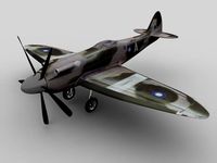
I recently got the Flitetest Spitfire https://store.flitetest.com/ft-spitfire-speed-build-kit/ and am loving it but I'm missing something from my build.... retractable landing gear.
Now it's near impossible to add real retracts to this because I'd be weakening the support beam that runs the length of the wing so I've designed a 3D printable kit that you can attach below the wing. As an added bonus I've included designs to add tail gear that you can attach to your rudder servo and steer the plane while on the runway. This all should be usable on other planes but be aware I designed this for the FT Spitfire so your mileage may vary. Below are 2 video's of the gear in action so you can see what to expect.
https://youtu.be/8UPuZH5VTbAhttps://youtu.be/CYrqGc_Ugq4
If you wish to edit this I have included the .SKP file (Google Sketchup) so you may edit this without converting the .STL
I have landed and take off with these however it should be noted the card layer on the foamboard may tear if the landing or surface is a bit rough. Print wise the more infil used the more versatile the gear will be. So far I've had to re-glue the gear to the wing once due to a bad landing. Maybe a wider base to spread load might be an idea.
---Required---
Other than a 3D printer and a plane to put this on you'll need:
Super Glue and/or Hot Glue
2x 9g Servo
2x Servo extension leads (200mm or more)
Servo Splitter (needed if you can't place each servo on it's own output on the receiver / FC)
Servo reverser (needed if you required the splitter)
Push Rod (for the tail wheel)
---Printing---
Included is a variety of files, you can choose to print them all in one go, as the assemblable sections or completely individually.
All parts should be done with 50% infill and a wall thickness of 1.2mm or more. Ideally the tail gear leg will want printing with more infill to give the pivot strength.
All parts are oriented in the most ideal position for best print quality. If you are having issues printing you may want to rotate them but some will be harder to remove support material.
To make support material easy to remove an angle of 70 degrees or more should be used at least in your slicer namely to avoid issues removing support from the servo housing.
---Assembly---
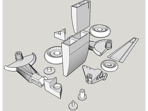
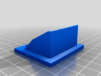
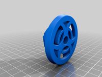
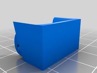
After all parts are printed and all support, brim and stringing has been removed test that the wheels fit in on their axles and that the retractable gear leg and pivot brace can twist. Please use the images in this thingiverse page for reference on assembly. There are exploded and assembled images for reference.
Having now familiarized yourself with the design with the included images we'll start with the retractable gear. You may want to do just one for now but if you're in a pinch for time go for both just ensure you're not mixing the parts. Take the retractable gear and a large wheel. try rotating it again on the axle, if it's able to spin freely take the wheel cap and place some glue on the thin rod. Slide that into the hole in the axle and press fit it. You may want to rotate the wheel as the glue sets to ensure any excess doesn't lock the wheels in place too.
While we wait for that to dry take your servo horn and glue it into the matching indentation on the retractable leg. Where the servo attaches must be facing out and not inside the gear. Try to get the centre of the pivot point on the horn aligned to the pivot point of the retractable leg else it may not function properly later on.
While the glue is setting place the servo in the servo enclosure, if printed correctly and to the correct size they should snugly fit inside. The servo must have the pivot point closest to the edge rather than the centre of the servo mount so that when retracted the gear doesn't cover the enclosure (see images if unsure) The cable must slide through the slot on the flat face so it can be routed through the wing later. You don't strictly need to glue this in if you press fit this on the wing later however you may glue this if you find this is looser than it should be.
Turn on your servo's to get them to centre themselves, skipping this step may lead to the servo not having enough throw to fully retract/extend the gear.
Assuming your glue is set from earlier (wait if not) you can place the 2 assemblies together so that the retractable leg is in the extended position (down) and perpendicular to the servo housing. This will be so it by default is down. Take your servo screw and lock the horn you glued earlier onto the servo.
Place the pivot brace onto the assembly and twist it about, the flat surfaces should be level with each other and can be tested by placing on a flat surface so it's facing upside-down. The stopper on the pivot brace should be against the flat face of the landing gear so that when extended it can't go any further, placing this on the wrong side will result in the gear not working correctly. Check the reference images in case you are unsure.
With the gear assembled you must position this on the plane wing so that the wheels are in front of the centre of mass and parallel. I have found 80mm from the front of the wing to the front of the servo housing and 20mm spacing between the fuselage and the servo housing worked for me. As long as you're happy with the placement and works for you then trace around the servo housing onto the wing.
Having traced out where you want to put the gear measure where your servo connector pokes through the slot and mark in the wing where that will be inside where you traced on the wing earlier. The hole only needs to be big enough to fit the connector through although you may want it slightly bigger to use wire later to pull this connector through the wing and into the fuselage. If your wings are stuck on this might be difficult although is possible.
If you have attached your wings to the fuselage don't panic, I did too and although this bit is a complete pain it's not impossible. You'll want some flexible wire to thread through the nose of the plane and into that hole between the wings where the other servo leads come through. When in try to get that wire to reach all the way down to the tip of the wing so that you can hold bot ends. If your wings are removable this is dead easy for you (Oh how I envy you)
When you have something coming out of both wing tips and the central hole in the wing to route wires in the fuselage start by cutting the holes for the servo connector to come through where you traced back in step 9. Don't cut out the entirety of where you traced the servo connector, just the small bit for the connector.
Now with the small hole try to wiggle the wire or whatever you used earlier until you can see it passing the hole you made. Pull the wire through the hole so that one end is now coming out this hole and the other is through the fuselage.
If you're using servo extenders attach one end of them to the wire at the hole end and gently pull it back through with the wire; Else use your servo connector amusing it's long enough. Ensure your knot is good enough too, last thing you want is it falling off and having to do step 10 again! When through and you have access to both ends tape down the connectors at the fuselage or plug them into your receiver / FC so you don't accidentally pull them back through. If you used extenders glue the servo connector to the connector so it doesn't detach in the wing and thread it through leaving you enough to apply glue.
Lets glue the landing gear on now. Messing this up may lead to trying again being messy so make sure you're in a position to apply glue and attach it with time to spare. Do these one at a time too so you have time to adjust the gear as it sets. Apply glue to the flat side of the servo housing and press that onto the wing where you drew an outline. you should be able to pull the cable through as you go to make the housing flush with the wing. Wiggle it into position then hold it in place while the glue sets.
Once set or enough that it won't slide easily apply glue to the flat surface of the pivot brace and and slide that onto the landing gear pivot while pressed onto the wing. At this point try rotating the gear to make sure it can move in the state you have glued it, if not adjust the pivot mount before it sets until it's all the way on the leg and able to move.
If successful the gear should happily raise and lower without too much effort and not flex too much thanks to the pivot brace. at this point you can adjust your trim and servo direction to fit your needs. If you are using a splitter and your servo's don't quite match up you can use a servo trimmer in line with one to adjust the difference.
Moving onto the tail we'll start by test fitting the wheel in the tail leg. It should spin freely in between the fork but if no try fling down any excess material. Test fit your pivot plate in the gap near the tail of your plane, it should fit snugly.
Before we fit the wheel into the fork lets put the leg into the plate. If you brake the leg doing this you'll have less to reprint later. Carefully try and pinch the pivot point and push it through the plate so that the flat side is against the flat part of the leg. The extruded bit shall fit inside the gap in your fuselage later.
Fit the axle into the fork with the wheel in and glue the cap in like you did with the retractable gear earlier. Spinning the wheel here while your glue sets will help prevent it locking up.
Take your push rod and bend one end so you can link it onto the rudder servo horn. Measuring or guessing correctly bend the other end so that it will mean that the wheel is in line with the rudder when fit in place. You may want to take your time with this bit.
Finally with the push rod linked through one of the small holes in the tail gear on the extended plate and the servo horn you can put glue along the topside of the flange on the pivot plate and press it into the spitfires tail portion.
Congrats, you're done and you have some inexpensive retractable landing gear for your foam-board FT Spitfire!
Happy flying and enjoy, feel free to comment and share your experience with the gear.
Lia <3
I recently got the Flitetest Spitfire https://store.flitetest.com/ft-spitfire-speed-build-kit/ and am loving it but I'm missing something from my build.... retractable landing gear.
Now it's near impossible to add real retracts to this because I'd be weakening the support beam that runs the length of the wing so I've designed a 3D printable kit that you can attach below the wing. As an added bonus I've included designs to add tail gear that you can attach to your rudder servo and steer the plane while on the runway. This all should be usable on other planes but be aware I designed this for the FT Spitfire so your mileage may vary. Below are 2 video's of the gear in action so you can see what to expect.
https://youtu.be/8UPuZH5VTbAhttps://youtu.be/CYrqGc_Ugq4
If you wish to edit this I have included the .SKP file (Google Sketchup) so you may edit this without converting the .STL
I have landed and take off with these however it should be noted the card layer on the foamboard may tear if the landing or surface is a bit rough. Print wise the more infil used the more versatile the gear will be. So far I've had to re-glue the gear to the wing once due to a bad landing. Maybe a wider base to spread load might be an idea.
---Required---
Other than a 3D printer and a plane to put this on you'll need:
Super Glue and/or Hot Glue
2x 9g Servo
2x Servo extension leads (200mm or more)
Servo Splitter (needed if you can't place each servo on it's own output on the receiver / FC)
Servo reverser (needed if you required the splitter)
Push Rod (for the tail wheel)
---Printing---
Included is a variety of files, you can choose to print them all in one go, as the assemblable sections or completely individually.
All parts should be done with 50% infill and a wall thickness of 1.2mm or more. Ideally the tail gear leg will want printing with more infill to give the pivot strength.
All parts are oriented in the most ideal position for best print quality. If you are having issues printing you may want to rotate them but some will be harder to remove support material.
To make support material easy to remove an angle of 70 degrees or more should be used at least in your slicer namely to avoid issues removing support from the servo housing.
---Assembly---
After all parts are printed and all support, brim and stringing has been removed test that the wheels fit in on their axles and that the retractable gear leg and pivot brace can twist. Please use the images in this thingiverse page for reference on assembly. There are exploded and assembled images for reference.
Having now familiarized yourself with the design with the included images we'll start with the retractable gear. You may want to do just one for now but if you're in a pinch for time go for both just ensure you're not mixing the parts. Take the retractable gear and a large wheel. try rotating it again on the axle, if it's able to spin freely take the wheel cap and place some glue on the thin rod. Slide that into the hole in the axle and press fit it. You may want to rotate the wheel as the glue sets to ensure any excess doesn't lock the wheels in place too.
While we wait for that to dry take your servo horn and glue it into the matching indentation on the retractable leg. Where the servo attaches must be facing out and not inside the gear. Try to get the centre of the pivot point on the horn aligned to the pivot point of the retractable leg else it may not function properly later on.
While the glue is setting place the servo in the servo enclosure, if printed correctly and to the correct size they should snugly fit inside. The servo must have the pivot point closest to the edge rather than the centre of the servo mount so that when retracted the gear doesn't cover the enclosure (see images if unsure) The cable must slide through the slot on the flat face so it can be routed through the wing later. You don't strictly need to glue this in if you press fit this on the wing later however you may glue this if you find this is looser than it should be.
Turn on your servo's to get them to centre themselves, skipping this step may lead to the servo not having enough throw to fully retract/extend the gear.
Assuming your glue is set from earlier (wait if not) you can place the 2 assemblies together so that the retractable leg is in the extended position (down) and perpendicular to the servo housing. This will be so it by default is down. Take your servo screw and lock the horn you glued earlier onto the servo.
Place the pivot brace onto the assembly and twist it about, the flat surfaces should be level with each other and can be tested by placing on a flat surface so it's facing upside-down. The stopper on the pivot brace should be against the flat face of the landing gear so that when extended it can't go any further, placing this on the wrong side will result in the gear not working correctly. Check the reference images in case you are unsure.
With the gear assembled you must position this on the plane wing so that the wheels are in front of the centre of mass and parallel. I have found 80mm from the front of the wing to the front of the servo housing and 20mm spacing between the fuselage and the servo housing worked for me. As long as you're happy with the placement and works for you then trace around the servo housing onto the wing.
Having traced out where you want to put the gear measure where your servo connector pokes through the slot and mark in the wing where that will be inside where you traced on the wing earlier. The hole only needs to be big enough to fit the connector through although you may want it slightly bigger to use wire later to pull this connector through the wing and into the fuselage. If your wings are stuck on this might be difficult although is possible.
If you have attached your wings to the fuselage don't panic, I did too and although this bit is a complete pain it's not impossible. You'll want some flexible wire to thread through the nose of the plane and into that hole between the wings where the other servo leads come through. When in try to get that wire to reach all the way down to the tip of the wing so that you can hold bot ends. If your wings are removable this is dead easy for you (Oh how I envy you)
When you have something coming out of both wing tips and the central hole in the wing to route wires in the fuselage start by cutting the holes for the servo connector to come through where you traced back in step 9. Don't cut out the entirety of where you traced the servo connector, just the small bit for the connector.
Now with the small hole try to wiggle the wire or whatever you used earlier until you can see it passing the hole you made. Pull the wire through the hole so that one end is now coming out this hole and the other is through the fuselage.
If you're using servo extenders attach one end of them to the wire at the hole end and gently pull it back through with the wire; Else use your servo connector amusing it's long enough. Ensure your knot is good enough too, last thing you want is it falling off and having to do step 10 again! When through and you have access to both ends tape down the connectors at the fuselage or plug them into your receiver / FC so you don't accidentally pull them back through. If you used extenders glue the servo connector to the connector so it doesn't detach in the wing and thread it through leaving you enough to apply glue.
Lets glue the landing gear on now. Messing this up may lead to trying again being messy so make sure you're in a position to apply glue and attach it with time to spare. Do these one at a time too so you have time to adjust the gear as it sets. Apply glue to the flat side of the servo housing and press that onto the wing where you drew an outline. you should be able to pull the cable through as you go to make the housing flush with the wing. Wiggle it into position then hold it in place while the glue sets.
Once set or enough that it won't slide easily apply glue to the flat surface of the pivot brace and and slide that onto the landing gear pivot while pressed onto the wing. At this point try rotating the gear to make sure it can move in the state you have glued it, if not adjust the pivot mount before it sets until it's all the way on the leg and able to move.
If successful the gear should happily raise and lower without too much effort and not flex too much thanks to the pivot brace. at this point you can adjust your trim and servo direction to fit your needs. If you are using a splitter and your servo's don't quite match up you can use a servo trimmer in line with one to adjust the difference.
Moving onto the tail we'll start by test fitting the wheel in the tail leg. It should spin freely in between the fork but if no try fling down any excess material. Test fit your pivot plate in the gap near the tail of your plane, it should fit snugly.
Before we fit the wheel into the fork lets put the leg into the plate. If you brake the leg doing this you'll have less to reprint later. Carefully try and pinch the pivot point and push it through the plate so that the flat side is against the flat part of the leg. The extruded bit shall fit inside the gap in your fuselage later.
Fit the axle into the fork with the wheel in and glue the cap in like you did with the retractable gear earlier. Spinning the wheel here while your glue sets will help prevent it locking up.
Take your push rod and bend one end so you can link it onto the rudder servo horn. Measuring or guessing correctly bend the other end so that it will mean that the wheel is in line with the rudder when fit in place. You may want to take your time with this bit.
Finally with the push rod linked through one of the small holes in the tail gear on the extended plate and the servo horn you can put glue along the topside of the flange on the pivot plate and press it into the spitfires tail portion.
Congrats, you're done and you have some inexpensive retractable landing gear for your foam-board FT Spitfire!
Happy flying and enjoy, feel free to comment and share your experience with the gear.
Lia <3
Similar models
thingiverse
free

Rc Plane Suspension Landing Gear by DanielWeppler07
... be glued right onto the wing or fuselage.
the same wheel is used for each design. the parts should fit together without sanding.
grabcad
free

SUPERMARINE SPITFIRE PART 11
... and suspension unit for the fixed wheel , there is also a retractable wheel, will have a go at this if i can find some drawings.
thingiverse
free
Simple Landing Gear with Retract Option by georgepapa
... in to the left and folding out to the right. i used micro servos for this, 1 servo per wheel.
model was designed using freecad.
grabcad
free

Retractable Landing Gear, For RC Planes
...aircraft and then sits on the outside.
note: servo model and servo arm, are not my models, however i believe them to be accurate
thingiverse
free

JSM Xcalibur Wing Servo Cable connector
...ng servo cable connector
thingiverse
made for 2/3 pc. servo extension connector
can be placed in the side holes of the fuselage.
thingiverse
free

Landing gear for 3dlabprints P51D mustang by donandtheresa
...landing gear from a decommissioned redcat foam p51 of similar design. the top plate, bottom plate, wire and wheels...
thingiverse
free

Aeronaut Triple - MPX Connector conversion kit
...e carefull not to glue the wing to the fuselage.
print in the orientation the stl loads and use supports for the mounting flange.
3dwarehouse
free

Fuselage with wing
...fuselage with wing
3dwarehouse
high wing tail dragger. landing gear is next. #airframe #airplane
thingiverse
free

GWS Spitfire Parts: Retractable Landing Gear Mount, Well and Cover by DU2RK
...g those lines all the way through the other side of the wing. some lightweight filler will be needed
https://youtu.be/vtz8l6psjh8
thingiverse
free

3Dlabprint spitfire landing gear by donandtheresa
...3 outline:2
10 - 20% infill.
once assembles i epoxied them on the bottom of the wing where the first joint was for added support.
Comikzink
thingiverse
free

Samsung Gear360 Dock (2016/2017) by ComikzInk
...em.
the 2016 side is setup so that it can sit on it's own or with a few mounts still attached below it like i have (see pics)
thingiverse
free

PlayStation / Xbox controller hybrid stand by ComikzInk
...ed.
only minor editing to the files by myself, most of the work in this was that of the two creators referenced and linked above.
thingiverse
free

Onewheel (Pint) Bearing Press Spacers by ComikzInk
...hub casing can crack the metal. you should only do this if you feel capable of pressing the bearing in straight with this method.
thingiverse
free

3 Bladed Prop Spinners by ComikzInk
...essary spacing in for the props however if you're unsure your prop will fit base 2 then try the base 1 will probably be best.
thingiverse
free

Flite Test Gremlin Battery Protector (skid plate) by ComikzInk
... as non-commercial as it includes the flitetest logo in which only they should have the right to sell work with their trademarks.
thingiverse
free

Onewheel Tyre Stand (With Alternative Versions) by ComikzInk
...
pinout for arduino
usb in provides 5v power.
arduino 5v -> led 5vin
arduino gnd -> led gnd
arduino pin 2 -> led data in
thingiverse
free
Onewheel Battery Capacity Display by ComikzInk
... lithium ion config) however for a v1 or plus you may need a different setting that matches your boards battery type and voltage.
thingiverse
free

DJI Mavic Pro 1 Angled Wall Mount by ComikzInk
....
i recommend using screws 70mm or longer with appropriate wall plugs. front to back of the screw hole is 50mm deep and 4mm wide.
thingiverse
free

FT Gremlin Carry Case (TJ Frame) by ComikzInk
...els unfortunately as i do not own them, feel free to remix the design if you do have it so others can enjoy the case :)
<3 lia
thingiverse
free

ImmersionRC Vortex 285 Angled Wall Mount by ComikzInk
...ble sided tape. simply place it where you want then drill into the wall through the pre-made hole in the mount and screw it down.
Swapable
thingiverse
free
Flitetest swapable series fire wall by coolpratheesh
...flitetest swapable series fire wall by coolpratheesh
thingiverse
flitetest swapable series fire wall
thingiverse
free

Flite Test Swapable Firewall by dlkj
...lkj
thingiverse
motor firewall for the flite test swapable power pod.
http://flitetest.com/articles/ft-swappable-power-pod-kit
thingiverse
free

Hot Swapable Lithopane Lamp by mijaz
...an slide in a lithopane 100x70.8 mm in size with 2mm frame thickness.
youtube tutorial for the complete project is in the works.
thingiverse
free

prinrbot plus v1 swapable tool mount by lmartinson
... prints are much cleaner now that the print head isn't so heavy. this design is also much more rigged then than the original.
thingiverse
free

Swapable Ultrabase brackets for Tevo Tornado by Microphobe
...ions or if something needs to be changed.
12/04/18 - by request added a v2 that contains pressure points to push in on the x axis
thingiverse
free
Pokemon red&blue plate by Jtachan
...by piece. the position of charizard and blastoise are swapable ...
thingiverse
free
FT Flite Test Swappable Power pod Firewall With Structural support by Phantomworks78
...i made to make a stronger firewall for the swapable power power pods made with rigidity and durability in...
thingiverse
free

Shopbot Desktop Chip Vacuum: Focused Attachment by bengineering
...focused attachment by bengineering thingiverse focused nozzle attachment with swapable nozzles for maximum vacuum pressure right around the cutting...
thingiverse
free
Stormbreaker ultra heavy assault tank by gwensdad2003
...2 levels of killing power and a row of swapable guns on each side this war machine has been...
Flitetest
thingiverse
free

FliteTest Firewall by justindp2006
...flitetest firewall by justindp2006
thingiverse
flitetest firewall for power pods. i use it on my spitfire and works great.
thingiverse
free
FliteTest control horn by FooRider
...flitetest control horn by foorider
thingiverse
control horn for rc airplanes designed by flitetest.
thingiverse
free
FliteTest Swappable firewall reinforced by Lubis
...flitetest swappable firewall reinforced by lubis
thingiverse
flitetest swappable firewall reinforced
updated: 2014-08-23
thingiverse
free

FliteTest Simple Cub Mods by bigfoot13
...flitetest simple cub mods by bigfoot13
thingiverse
mods that i've made to my flitetest simple cub.
thingiverse
free
Flitetest swapable series fire wall by coolpratheesh
...flitetest swapable series fire wall by coolpratheesh
thingiverse
flitetest swapable series fire wall
thingiverse
free

FliteTest Mig 3 Canopy by jhallett
...tetest mig 3 canopy by jhallett
thingiverse
canopy for flitetest mig-3. print in vase mode and trim edges with scissors for fit
thingiverse
free

Flitetest Mini Arrow Vertical Stabilizer by robhsaunders
...flitetest mini arrow vertical stabilizer by robhsaunders
thingiverse
vertical stabilizer for flitetest's mini arrow.
thingiverse
free
Biohazard Gimbal Protectors by flitetest
...biohazard gimbal protectors by flitetest
thingiverse
biohazard gimbal protectors
thingiverse
free
Micro RunCam Insert by flitetest
...micro runcam insert by flitetest
thingiverse
micro runcam insert
thingiverse
free

Flitetest - FT Mini Control Horn by SidneyKi
... sidneyki
thingiverse
this is the control horn for the flitetest mini airplanes.http://store.flitetest.com/aircraft-accessories/
Spitfire
3ddd
$1

Eichholtz Spitfire
...eichholtz , spitfire
http://www.eichholtz.com/lamp-spitfire-0084000233114.aspx
turbosquid
free

Spitfire
... available on turbo squid, the world's leading provider of digital 3d models for visualization, films, television, and games.
turbosquid
$15

Spitfire
...l spitfire mk1a for download as blend, max, fbx, dae, and obj on turbosquid: 3d models for games, architecture, videos. (1685284)
3d_export
$5
Spitfire 3D Model
...spitfire 3d model
3dexport
spitfire airplane
spitfire 3d model victormaciel 36251 3dexport
3d_export
$10

Spitfire 3D Model
...spitfire 3d model
3dexport
spitfire plane ww2 iphone android low poly cheap
spitfire 3d model *shine 32289 3dexport
3ddd
$1
Lamp SPITFIRE
...lamp spitfire
3ddd
eichholtz
lamp spitfire от производителя eichholtz
диаметр 40 мм
высота 66 мм
артикул 105586
3d_ocean
$15
Supermarine Spitfire
...port war world worldwar ww ww2 wwii
low polygon and very well detailed supermarine spitfire. check out my profile for more items!
turbosquid
$149
SPITFIRE MKIXC
... available on turbo squid, the world's leading provider of digital 3d models for visualization, films, television, and games.
turbosquid
$60

supermarine spitfire
... available on turbo squid, the world's leading provider of digital 3d models for visualization, films, television, and games.
turbosquid
$35
SPITFIRE.3DS
... available on turbo squid, the world's leading provider of digital 3d models for visualization, films, television, and games.
Retractable
turbosquid
$10

Retractable Clothesline
...ractable clothesline for download as blend, dae, fbx, and obj on turbosquid: 3d models for games, architecture, videos. (1579308)
turbosquid
$49

Retractable Hiking Pole
...lty free 3d model retractable hiking pole for download as max on turbosquid: 3d models for games, architecture, videos. (1639636)
turbosquid
$16

Retractable cable lock
...able cable lock for download as blend, fbx, stl, obj, and dae on turbosquid: 3d models for games, architecture, videos. (1629661)
3d_ocean
$12

Retractable pull low poly
...ble pull low poly
3docean
3d 3ds max furniture modern rounded forms sofa vintage nubuk leather
retractable pull low poly animated
3d_ocean
$3

Retractable Ballpoint-Pen
...ek black-and-clear design make it perfect for any situation. it is not rigged, as it is two separate pieces, the casing and th...
turbosquid
$20

RETRACTABLE BLEACHERS 3D model
...el retractable bleachers 3d model for download as max and fbx on turbosquid: 3d models for games, architecture, videos. (1259004)
3d_export
$10

retractable clothesline
...gically named.<br>other formats<br>=================<br>- collada (.dae)<br>- autodesk fbx<br>- obj
turbosquid
$29

UFO 11 Retracting Landing gear
... available on turbo squid, the world's leading provider of digital 3d models for visualization, films, television, and games.
3d_export
free

retractable barrier
...: 1510<br>texture: jpg<br>materials: yes<br>for any questions, please contact us and we'll respond quickly.
3ddd
$1
шасси для рамы DJI S800
...dji cкладывающиеся шасси для рамы dji s800 dji s800 retractable landing...
Landing
3d_export
free

land
...land
3dexport
3d_export
$20

land rover
...land rover
3dexport
land rover
3d_export
$65
landing
...landing
3dexport
simple rendering of the scene file
3ddd
free
Land Bond
... тумба
land bond-авторская коллекция мебели жана франсуа роле.сделана из натуральной древесины.
3ddd
$1
Land Bond
...land bond
3ddd
land bond-авторская коллекция мебели жана франсуа роле.
3ddd
$1

Land Bond
...land bond
3ddd
land bond-авторская коллекция мебели жана франсуа роле
3ddd
free

dream land / sicilia
...dream land / sicilia
3ddd
dream land
dream land sicilia
3ddd
$1

Dream Land / Монтсеррат
...dream land / монтсеррат
3ddd
dream land , капитоне
производитель: dream land
design_connected
$29

Land Sofa
...land sofa
designconnected
alivar land sofa computer generated 3d model. designed by bavuso, giuseppe.
design_connected
$27

Land Meridiana
...land meridiana
designconnected
bonaldo land meridiana computer generated 3d model. designed by crs bonaldo.
Gear
3d_ocean
$4
Gears
...gears
3docean
gear gears iron
4 different size of gears
3d_export
$5
gear
...gear
3dexport
gear
3d_export
free
Gears
...gears
3dexport
gears
3d_export
$5
gear
...gear
3dexport
a simple model of gear
3d_export
$5
gear
...gear
3dexport
gear for transmission , case machine
3d_ocean
$3
Gears
...nical parts process steampunk vehicle wheel work
10 different gear models volume 01-10 files: .3ds .c4d .obj note: you need vray
3d_ocean
$1

Spur Gear
...spur gear
3docean
decoration gear
a typical spur gear
3d_ocean
$4
Gear wheels
...gear wheels
3docean
engine engineering gear gears industry machinery mechanical toothwheel wheel
pair of gear wheels : animated.
turbosquid
$9
Gear
...gear
turbosquid
royalty free 3d model gear for download as on turbosquid: 3d models for games, architecture, videos. (1712328)
turbosquid
$2
Gears
...rs
turbosquid
royalty free 3d model gears for download as ma on turbosquid: 3d models for games, architecture, videos. (1166710)