GrabCAD

Flexure Handrail Clamp
by GrabCAD
Last crawled date: 2 years ago
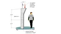
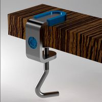
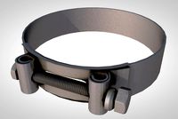
Figure 1: Clamp installed with mounting adapter attached and secured.
- Securing mounting adapter creates tension in flexure and increases clamping force.
- Flexure can see 120 lbf of tension due to securing mounting adapter and external loading before start of yield.
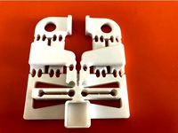
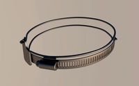
Figure 2: Clamp in free state, as printed.
- Z-axis parallel to handrail length direction.
- Flexure curved with parabolic profile in free state.
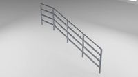
Figure 3: Clamp installed on handrail.
- Flexure becomes straight when installed on handrail.
- Light clamping force of approximately 1.3 lbf before mounting adapter is attached and secured.
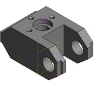
Figure 4: Installation steps.
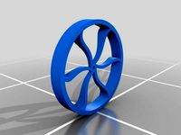
Figure 5: Cross-sectional view showing internal construction.
- Internal honeycomb construction - lightweight and rigid.
- Chamfers between honeycomb walls and clamp side walls to keep maximum overhang at 45 degrees.
Figure 6: FEA results for maximum flex during installation.
- 2D plane strain nonlinear (large displacement) FEA analysis.
- Flexure sees 95% of yield stress during installation.
Figure 7: FEA results for clamp installed on handrail.
- Flexure sees 48% of yield stress when installed on handrail.
- Flexure can see an additional 120 lbf of tension before yield.
- Securing mounting adapter creates tension in flexure and increases clamping force.
- Flexure can see 120 lbf of tension due to securing mounting adapter and external loading before start of yield.
Figure 2: Clamp in free state, as printed.
- Z-axis parallel to handrail length direction.
- Flexure curved with parabolic profile in free state.
Figure 3: Clamp installed on handrail.
- Flexure becomes straight when installed on handrail.
- Light clamping force of approximately 1.3 lbf before mounting adapter is attached and secured.
Figure 4: Installation steps.
Figure 5: Cross-sectional view showing internal construction.
- Internal honeycomb construction - lightweight and rigid.
- Chamfers between honeycomb walls and clamp side walls to keep maximum overhang at 45 degrees.
Figure 6: FEA results for maximum flex during installation.
- 2D plane strain nonlinear (large displacement) FEA analysis.
- Flexure sees 95% of yield stress during installation.
Figure 7: FEA results for clamp installed on handrail.
- Flexure sees 48% of yield stress when installed on handrail.
- Flexure can see an additional 120 lbf of tension before yield.
Similar models
grabcad
free

FEA of Solar Panel Mounting Structure
...id this analysis on the request of one of my friend. it took me quite a while to figure out the final dimensions of the elements.
3dwarehouse
free
MechMat - An Eccentric Compressive Force (Combined Axial and Flexural Stress) (LE33)
...ial and flexural stress) (le33)
3dwarehouse
mechmat - an eccentric compressive force (combined axial and flexural stress) (le33)
grabcad
free

External Spur Gear Root Fillet Stress Analysis
...ults in the attached pdf files.
if you have any questions or opinion please share with me in the comments section!
thank you! :)
grabcad
free

SGCHL Donkey Calf Raise Attachment
...
displacement
maximum 0.025 mm
stress
minimum 0.000394 megapa
maximum 35 megapa
factor of safety
minimum 0.788
maximum 3.5e+007
grabcad
free

Flexural or Bending Stress Analysis
...flexural or bending stress analysis
grabcad
flexural stress
thingiverse
free

Lamp LED Tripod Adapter by oliviers68
...y a clamping lever. thread the strap into the adapter and secure the lamp. very handy outdoors for camping, construction, diy ...
thingiverse
free

Vernier Force Sensor adapter for Pasco Cart by bfuller181
...tach a vernier dual-range force sensor atop a pasco cart. for secure mounting, use a pasco screw to attach through provided hole.
grabcad
free

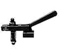
NASA Handrail Clamp-dz
...f attachment and easy of removal; stability of attachment.
dimension of clamp:
x = 2.3 inches
y = 1.3 inches
z = 2 inches
thinks
grabcad
free

Donkey Calf Raise
...esults :- fea stress results 1500 pounds of compressive force.pdf & report fea stress results.rar
-fea stress results vidéo
grabcad
free

CHAMP challenge clamp submissions
...assembly on. once the handrail is in the slot, the latch is closed over the handrail and the assembly is secured to the handrail.
Flexure
cg_studio
$70

Digestive System in a Human Body3d model
...anus spleen acending colon duodenum splenic flexura transverse hepatic flexure sigmoid jejunum rectum head mouth teeth throat gum tooth...
thingiverse
free
Flexure by CBUEngineering
...flexure by cbuengineering
thingiverse
flexure part limits translational motion in the x direction
thingiverse
free

Flexure ball by CBUEngineering
...flexure ball by cbuengineering
thingiverse
this flexure ball limits motion of the middle section to just the x direction.
thingiverse
free

Spherical flexure joint by Mr_SeLeNiO
...joint by mr_selenio
thingiverse
attempt to first spherical flexure joint design from https://www.youtube.com/watch?v=dangcygu7tc
thingiverse
free

Flexure Stages by DarynFinney
...sign and print my own flexure stages. i was using m2 hardware for the adjustment; would have worked better if i added knobs.
2014
thingiverse
free

Cross-Axis Flexure Pivot by BYU_CMR
... other. cross-axis flexure pivots can replace pin joints in applications where wear and/or friction need to be low or eliminated.
thingiverse
free
Flexure parallel gripper by nraynaud
... education on flexures.
i had best results with my pla when the thinest part of the hinge was 0.4mm, and the hinge width is 10mm.
thingiverse
free

Flexure - Spiral Disk by CBUEngineering
...flexure - spiral disk by cbuengineering
thingiverse
limits motion in the y direction
thingiverse
free

Jubilee Tool Compression Flexures by reicheltcm
... are flexures needed for the jubilee toolchanger tools. normally these are laser cut and purchased but now you can 3d print them.
thingiverse
free

Hand Held Flexure Pliers by crreed
... scale to whatever size works best for you.
see full write up below:http://www.inventionfactory.xyz/2016/02/flexure-pliers.html
Handrail
3d_export
$5
handrail
...handrail
3dexport
handrail
3d_export
free
handrail
...handrail
3dexport
handrail
archibase_planet
free

Handrail
...handrail
archibase planet
handrail railing guard-rail
handrail n270913 - 3d model (*.gsm+*.3ds) for interior 3d visualization.
archibase_planet
free
Handrail
...l
archibase planet
handrail railing guard-rail
handrail for stair n020813 - 3d model (*.gsm+*.3ds) for interior 3d visualization.
archibase_planet
free
Handrail
...drail
archibase planet
handrail railing guard-rail
handrail stair n030114 - 3d model (*.gsm+*.3ds) for interior 3d visualization.
archibase_planet
free
Handrail
...handrail
archibase planet
railing handhold parapet
handrail n050710 - 3d model (*.3ds) for interior 3d visualization.
archibase_planet
free
Handrail
...handrail
archibase planet
banisters railing guard-rail
handrail n070710 - 3d model (*.3ds) for interior 3d visualization.
archibase_planet
free
Handrail
...handrail
archibase planet
banisters hand-rail railing
handrail n020710 - 3d model (*.gsm+*.3ds) for interior 3d visualization.
archibase_planet
free

Handrail vase
...se planet
handrail vase flower handrail vase
handrails vase n180813 - 3d model (*.gsm+*.3ds+*.max) for exterior 3d visualization.
3ddd
$1
Handrail 1
...handrail 1
3ddd
перила
wooden handrail old style
Clamp
3d_export
$11

clamp
...clamp
3dexport
clamp
3ddd
free

Clamp
... enricо zanolla , капитоне
дизайнерenrico zanollмодель clamp
3ddd
$1
Clamp
...ricо zanolla , капитоне
дизайнеры
enrico zanolla
andrea di filippo
модель clamp
dzstudio
3d_export
free
clamp
...clamp
3dexport
simple clamp model, more free 3d models here:
3d_export
$5
clamping handle
...clamping handle
3dexport
clamping handle
3ddd
$1
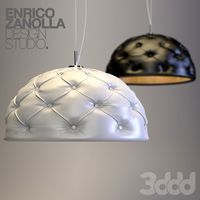
Clamp / DZstudio
... dzstudio , капитоне
люстра clamp от dzstudio/enrico zanolla(италия).
3ddd
$1
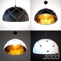
Светильник Clamp
...светильник clamp
3ddd
clamp
стеганый светильник clamp в двух цветах в черном и белом.
turbosquid
$29
clamp
...ty free 3d model clamp for download as 3ds, obj, c4d, and fbx on turbosquid: 3d models for games, architecture, videos. (1442049)
turbosquid
$29
clamp
...ty free 3d model clamp for download as 3ds, obj, c4d, and fbx on turbosquid: 3d models for games, architecture, videos. (1442041)
3d_export
$5
Clamp-14
...clamp-14
3dexport
3d model of clamp name 14