Thingiverse
Filament Runout Sensor for EZR Struder Ender 3 by dbp3D
by Thingiverse
Last crawled date: 3 years, 4 months ago
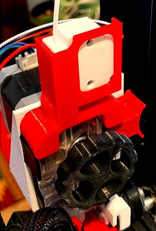
Filament Runout Sensor for EZR Struder Ender 3
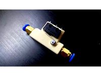
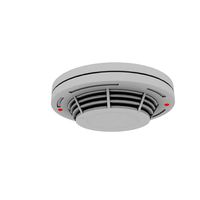
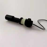
OVERVIEW:
This filament runout sensor + bracket is designed for an Ender 3 (Pro) with direct drive EZR Struder, used with TPU or any other filament. The sensor costs less than $5 from AliExpress, including a cable. (Note: I bought two sensors (with cables) so I could cut and solder the two cables together to make a long cable.) https://www.aliexpress.com/item/33028816768.html?spm=a2g0o.productlist.0.0.6fcc744bNX9yD3&algo_pvid=9438d87f-1666-454f-b92e-f0eefa71a679&algo_expid=9438d87f-1666-454f-b92e-f0eefa71a679-1&btsid=0b0a555f16109894313648923e845d&ws_ab_test=searchweb0_0,searchweb201602_,searchweb201603_
REQUIREMENTS:
Some soldering may be required to lengthen or shorten the cable to fit your printer. Also, some soldering is required to modify the switch inside the runout sensor.
The firmware must be modified. It is recommended that you save a copy of each firmware version in case you need to revert to a previous version of the firmware.
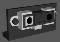
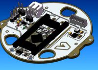
SWITCH MODIFICATION:
Pry open the sensor housing as follows. Insert needle nose pliers into the long slot on the end of the sensor, and pull the pliers handles apart to separate the halves of the housing. On the circuit board, the three pins at the bottom of the switch are COM (Common), NO (Normally Open), and NC (Normally Closed). Cut the middle (NO) pin close to the switch body. Bend the NO pin away from the switch body. Solder a jumper wire from the NO pin to the NC pin. https://photos.app.goo.gl/5FJjWY1ThLaMc5T46
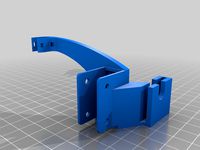
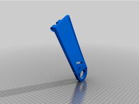
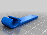
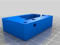
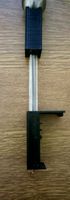
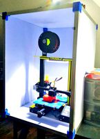
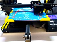
PRINT BRACKET:
Print the bracket. I used PETG, 20% infill and support. PLA should work fine.
CONNECT WIRES TO THE PRINTER CIRCUIT BOARD
The cable has three wires for: CTRL, GND, +5V. The +5V wire powers the LED in the sensor. The CTRL and GND wires sense when the filament sensor switch is CLOSED (no filament present) and OPEN (filament present). This video will help you decide which pin to use for the CTRL wire. https://www.youtube.com/watch?v=UL_DzCfwSjg&ab_channel=DorkyTim
FIRMWARE UPDATE
This video goes over the basics of modifying firmware. https://www.youtube.com/watch?v=GQlAN88ebNM&ab_channel=FusionSource-3DPrinting
This also helps with modifying firmware for a filament runout sensor. https://www.youtube.com/watch?v=5Jt-Qc67FDo&ab_channel=Crosslink
This is a good one. https://www.youtube.com/watch?v=6023oBYmXW4&ab_channel=Crosslink
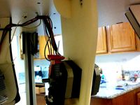
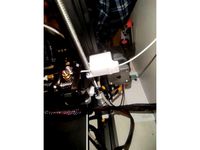
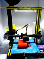
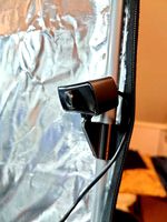
BRACKET DURING PRINT
Here is a short video. https://photos.app.goo.gl/mH81YrJ4YQAgx8tk8
OVERVIEW:
This filament runout sensor + bracket is designed for an Ender 3 (Pro) with direct drive EZR Struder, used with TPU or any other filament. The sensor costs less than $5 from AliExpress, including a cable. (Note: I bought two sensors (with cables) so I could cut and solder the two cables together to make a long cable.) https://www.aliexpress.com/item/33028816768.html?spm=a2g0o.productlist.0.0.6fcc744bNX9yD3&algo_pvid=9438d87f-1666-454f-b92e-f0eefa71a679&algo_expid=9438d87f-1666-454f-b92e-f0eefa71a679-1&btsid=0b0a555f16109894313648923e845d&ws_ab_test=searchweb0_0,searchweb201602_,searchweb201603_
REQUIREMENTS:
Some soldering may be required to lengthen or shorten the cable to fit your printer. Also, some soldering is required to modify the switch inside the runout sensor.
The firmware must be modified. It is recommended that you save a copy of each firmware version in case you need to revert to a previous version of the firmware.
SWITCH MODIFICATION:
Pry open the sensor housing as follows. Insert needle nose pliers into the long slot on the end of the sensor, and pull the pliers handles apart to separate the halves of the housing. On the circuit board, the three pins at the bottom of the switch are COM (Common), NO (Normally Open), and NC (Normally Closed). Cut the middle (NO) pin close to the switch body. Bend the NO pin away from the switch body. Solder a jumper wire from the NO pin to the NC pin. https://photos.app.goo.gl/5FJjWY1ThLaMc5T46
PRINT BRACKET:
Print the bracket. I used PETG, 20% infill and support. PLA should work fine.
CONNECT WIRES TO THE PRINTER CIRCUIT BOARD
The cable has three wires for: CTRL, GND, +5V. The +5V wire powers the LED in the sensor. The CTRL and GND wires sense when the filament sensor switch is CLOSED (no filament present) and OPEN (filament present). This video will help you decide which pin to use for the CTRL wire. https://www.youtube.com/watch?v=UL_DzCfwSjg&ab_channel=DorkyTim
FIRMWARE UPDATE
This video goes over the basics of modifying firmware. https://www.youtube.com/watch?v=GQlAN88ebNM&ab_channel=FusionSource-3DPrinting
This also helps with modifying firmware for a filament runout sensor. https://www.youtube.com/watch?v=5Jt-Qc67FDo&ab_channel=Crosslink
This is a good one. https://www.youtube.com/watch?v=6023oBYmXW4&ab_channel=Crosslink
BRACKET DURING PRINT
Here is a short video. https://photos.app.goo.gl/mH81YrJ4YQAgx8tk8
Similar models
thingiverse
free

Filament Runout Sensor using Z limit switch by Thefahmialias
... to extend the wire..connect to the filament runout port on the mainboard. flash jyer firmware and enable filament runout sensor.
grabcad
free

20 cents Ender 3 V2 Filament Sensor
...as shown in the last picture.
you may need a longer m3 screw to secure it in place where the threaded nut of the z-axis is fixed.
thingiverse
free

Filament Runout Sensor by laubed
...s/configuration/configuration.html#filament-runout-sensor
smoothieware: http://smoothieware.org/switch#pause-when-out-of-filament
thingiverse
free

Filament Runout Sensor Slim Variant by sheldonopolis
...s/configuration/configuration.html#filament-runout-sensor
smoothieware: http://smoothieware.org/switch#pause-when-out-of-filament
thingiverse
free

Filament Runout Sensor for Scalar 3D Printers by 3DModularSystems
...ww.3dmodularsystems.com
twitter: https://twitter.com/3dmodularsystem
youtube: http://www.youtube.com/c/3dmodularsystems3dprinters
thingiverse
free

Cable hanger - EZR STRUDER
...nder 3 withan ezr struder.
it just fits into the recesses of the top cover and allows the cables to run under the extruder lever.
thingiverse
free

Ender-3 or CR10 Filament Runout Sensor with Filament Guide
...ions available on the internet.
there are too many possibilities depending on the controller board and creality
printer you have.
thingiverse
free

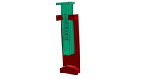
Filament Runout Sensor Bracket for Ender 3 with red dual gear extruder by JakeTri
...ews used to attach the filament runout sensor bracket.
bolts needed to secure sensor on the bracket: two m3 x 20 with two m3 nuts
thingiverse
free
Ender 3 Filament runout sensor with cable management without screws
...to my youtube channel https://www.youtube.com/c/3dmakeres , you can also make a donation to my paypal account 3dmakeres@gmail.com
thingiverse
free

Filament runout sensor ender by davidcnns
...will also work.
remember to update the marlin firmware and to set the correct pin for the switch:
define fil_runout_pin z_min_pin
Dbp3D
thingiverse
free

Cheshire Collimating Eyepiece by dbp3D
...5" focuser.
i have created collimation instructions at this link:https://dbpeckham.com/telescope/collimation/collimation.htm
thingiverse
free

Low Profile Knob For 1/4 Inch Capscrew by dbp3D
... capscrew is inserted into the knob, threads first. i used needle-nose pliers to press the hex-head firmly under the three tabs.
thingiverse
free
Stable Folding Banjo Stand by dbp3D
...ed positions.
the front and rear legs are in two parts and are glued with epoxy. the top parts each have a tab that is glued in.
thingiverse
free
Stable Folding Banjo Stand by dbp3D
...ed positions.
the front and rear legs are in two parts and are glued with epoxy. the top parts each have a tab that is glued in.
thingiverse
free
Stable Folding Banjo Stand by dbp3D
...ed positions.
the front and rear legs are in two parts and are glued with epoxy. the top parts each have a tab that is glued in.
Ezr
thingiverse
free

EZR Struder for the Hydro by Steve32060
...ezr struder for the hydro by steve32060
thingiverse
wanted to use my ezr...so i adapted a re-mix
thingiverse
free
Cable hanger - EZR STRUDER
...nder 3 withan ezr struder.
it just fits into the recesses of the top cover and allows the cables to run under the extruder lever.
thingiverse
free

Ezr strooder Filament run our sensor
...our sensor
thingiverse
simple filament run our sensor for the ezr strooder. needs a "clicky thing" switch from amazon.
thingiverse
free

CR6 SE Filament Guide for EZR Struder by zer0ss
...cr6 se filament guide for ezr struder by zer0ss
thingiverse
remixed the cprints cr 6 se filament guide to fit the ezr struder.
thingiverse
free

EZR Extruder Cable Chain Mount by siskulous
...niewhiskey's ender 3 cable chains that attaches to the ezr extruder. i'm using this to go from the extruder to my hotend.
thingiverse
free
Ender 3 V2 EZR Struder adapter plate by Jomahu
...ender 3 v2 ezr struder adapter plate by jomahu
thingiverse
adapter plate to use seemecnc ezr struder in the ender 3 v2 printer.
thingiverse
free

EZR Fitting for PTFE tube by juanyunis
...truder doesn't have a way to connect the tube, so i created this one.
it is necessary to get longer screws, i used 2 m3x20mm.
thingiverse
free
Ender 3 EZR Extruder Cable Clip
... end was supported by a clip built into the stock extruder. the cut out part is a little tight but it holds the loom very secure.
thingiverse
free

SeeMeCNC EZR Struder Mount for 2020 i3 Clone by JT_Shop
...nt for the seemecnc ezr struder to mount to a 2020 vertical frame like the chinese i3 clone. the "nut" need 2 3mm nuts.
thingiverse
free

Ender 3 Filament Guide for SeeMeCNC EZR Struder
...e was designed to work with your mosaic palette2. it can also be used just fine without a palette.
you can print without support.
Struder
thingiverse
free

Air-B-Struder by Barrocas
... 4.8mm zip-ties.
if you want to add a suspended counter-weight, just tie it to the zip-tie on top of the motor.
simple and easy.
thingiverse
free
EZ Struder Mount by Curt123
...lso need the same hardware you use for the stock mount and of course an ez struder from seemecnc. hope someone finds this useful.
thingiverse
free
Cable hanger - EZR STRUDER
...nder 3 withan ezr struder.
it just fits into the recesses of the top cover and allows the cables to run under the extruder lever.
thingiverse
free

Libro-Struder 2 by PCCLDideafactory
...f pinching action between a small set of rollers lets this mechanism grip and push filament with high power and without slipping.
thingiverse
free
CR6 SE Filament Guide for EZR Struder by zer0ss
...cr6 se filament guide for ezr struder by zer0ss
thingiverse
remixed the cprints cr 6 se filament guide to fit the ezr struder.
thingiverse
free
EZR Struder for the Hydro by Steve32060
...ezr struder for the hydro by steve32060
thingiverse
wanted to use my ezr...so i adapted a re-mix
thingiverse
free
Ender 3 V2 EZR Struder adapter plate by Jomahu
...ender 3 v2 ezr struder adapter plate by jomahu
thingiverse
adapter plate to use seemecnc ezr struder in the ender 3 v2 printer.
thingiverse
free

Tinkey Struder by scottmayson
...ad body for j-head mk v-b and a minebea geared stepper motor. 215grams total weight.
designed for my delta printer - coming soon.
thingiverse
free

A-Struder remix - counterweight loop by mrtinkerer
...rer
thingiverse
remix of this by nebbianhttp://www.thingiverse.com/thing:1259941
added a place to attach a counterweight string.
thingiverse
free
SeeMeCNC EZR Struder Mount for 2020 i3 Clone by JT_Shop
...nt for the seemecnc ezr struder to mount to a 2020 vertical frame like the chinese i3 clone. the "nut" need 2 3mm nuts.
Runout
3d_export
$6
clamping mechanism of heavy workpiece
...load<br>the inertia force at the maximum acceleration of horizontal runout is less than the retraction side thrust of cylinder.<br>selection...
thingiverse
free
Filament runout sensor by TA1AUB
...filament runout sensor by ta1aub
thingiverse
filament runout sensor
thingiverse
free
Runout filament sensor by davidix68
...runout filament sensor by davidix68
thingiverse
ender 3 runout sensor microswitch case
thingiverse
free
runout sensor -bowden by chroja
...runout sensor -bowden by chroja
thingiverse
runout sensor -bowden
v5 optimalize design
thingiverse
free

Filament runout sensor by jos
.../webshop/cartesio-shop/electronics/filament-runout-sensor
for assembly :http://mauk.cc/mediawiki/index.php/filament_runout_sensor
thingiverse
free

Filament runout by pochetto
...y pochetto
thingiverse
easy filament runout.
1 endstop
1 led
nel firmware attivare la funzione di fine filo e assegnare un pin.
thingiverse
free

Filament runout sensor support by 100s99s
...filament runout sensor support by 100s99s
thingiverse
support for filament runout sensor of direct drive.
thingiverse
free

Swivel mount runout sensor by notnyt
...swivel mount runout sensor by notnyt
thingiverse
608 bearing mounted filament runout sensor
thingiverse
free

Filament runout sensor fastener by Cherepok
...filament runout sensor fastener by cherepok
thingiverse
movable adjustable mount for bigtreetech filament runout sensor.
thingiverse
free

Runout gauge for pulley by tom4cad
...runout gauge for pulley by tom4cad
thingiverse
20t pulley with 5 mm bore. measured runout 0,07 mm
edit
tool with 8mm hole added
Ender
3ddd
$1
Enders / Elegance
...enders / elegance
3ddd
обогреватель
уличный газовый обогреватель enders elegance
высота: 2200 мм
3d_export
free
ender 3 frame cavity covers
... of the creality ender 3 - makes it look a bit more attractive it just slides into the open channels of the aluminium framework
turbosquid
$1
pen support for ender 3
...y free 3d model pen support for ender 3 for download as blend on turbosquid: 3d models for games, architecture, videos. (1611282)
3d_ocean
$9
Ender Dragon Minecraft
...ojang obj poly videogames
ender dragon minecraft created with cinema 4d r15 formats included: max 2013 – fbx 2012 – c4d r15 – obj
3d_export
free
Creality ender enclosure webcam mount
...e creality enclosure. sure is better than a tripod. change it up if it helps. i printed pla with 50% infill on my dd ender 3 pro.
3d_export
free
ender 3 enclosure corners
...er corners and 4 upper corners, using 25mmx25mm angled aluminium pieces that gets covered on inside of the frame with plexiglass
3d_export
free
ender 3 3d print bed clips
...ed + normal aluminium bed frame of the creality ender 3 = 6mm (b) these clips are designed for glass plate + aluminium bed = 4mm
3d_export
$5
GRUMPY CAT
...grumpy cat 3dexport grumpy cat to print in ender ...
3d_export
$5

Logs fire
...with one multi material for corona and vray r ender. albedo, normal, uvmap, roughness format jpg 4096x4096 models:...
3d_export
$42

excavator
...is the original size. 0.12 mm printing surface creality ender5 ...
Sensor
3d_export
free

parking sensor
...parking sensor
3dexport
car parking sensor
turbosquid
$1
Sensor
... available on turbo squid, the world's leading provider of digital 3d models for visualization, films, television, and games.
3d_export
$5
Smoke sensor
...port
smoke sensor, can be an impressive element for your projects. easy to use, realistic image, low polygon, quality materials.
3d_export
$5
Air Quality Sensor v1
...air quality sensor v1
3dexport
air quality sensor v1
3d_export
$15
float sensor
...e up render. - all parts and materials are logically named. other formats ================= - collada (.dae) - autodesk fbx - obj
turbosquid
$26
Wind sensor C
...free 3d model wind sensor c for download as 3ds, obj, and fbx on turbosquid: 3d models for games, architecture, videos. (1328943)
turbosquid
$26
Wind sensor B
...free 3d model wind sensor b for download as 3ds, obj, and fbx on turbosquid: 3d models for games, architecture, videos. (1328168)
3d_export
$5
ultrasound sensor
...ivers convert ultrasound into electrical signals, and transceivers can both transmit and receive ultrasound. export in: -obj -fbx
3ddd
free
Вытяжка Shindo pallada sensor
... вытяжка
вытяжка shindo pallada sensor. в двух размерах - 600 и 900. текстуры в комплекте.
turbosquid
$52
Wind sensor A B C
...
royalty free 3d model wind sensor a b c for download as fbx on turbosquid: 3d models for games, architecture, videos. (1408406)
Filament
3ddd
$1
Filament Cage
...filament cage
3ddd
лофт , filament cage
модель бра, делалась по фото!
turbosquid
$3
FILAMENT COUNTER
...d
royalty free 3d model filament counter for download as stl on turbosquid: 3d models for games, architecture, videos. (1563049)
3d_export
$5

Filament lamp 3D Model
...filament lamp 3d model
3dexport
filament lamp 3d model kevin 54161 3dexport
3d_export
$5

Filament bulb candle 3D Model
...filament bulb candle 3d model
3dexport
filament bulb-candle
filament bulb candle 3d model kevin 54163 3dexport
3d_export
$5

Filament led light bulb
...filament led light bulb
3dexport
realistic 3d model of filament light bulb with v-ray materials.
3d_export
$5

Filament led light bulb
...filament led light bulb
3dexport
realistic 3d model of filament light bulb with v-ray materials.
3d_export
$5

Filament led light bulb
...filament led light bulb
3dexport
realistic 3d model of filament light bulb with v-ray materials.
3d_export
$5
Filament led light bulb
...filament led light bulb
3dexport
realistic 3d model of filament light bulb with v-ray materials.
3d_export
$5

Filament led light bulb
...filament led light bulb
3dexport
realistic 3d model of filament light bulb with v-ray materials.
3ddd
$1
Factory filament metal shade
...factory filament metal shade
3ddd
restoration hardware
restoration hardware. 20th c. factory filament metal shade.
3
turbosquid
$10
Mountain Bike 3 -3 of 3
...model mountain bike 3 (#3 of 3) for download as fbx and blend on turbosquid: 3d models for games, architecture, videos. (1438752)
turbosquid
$6

Rock 3-3
...urbosquid
royalty free 3d model rock 3-3 for download as obj on turbosquid: 3d models for games, architecture, videos. (1628065)
turbosquid
$29
Books 150 pieces 3-3-3
...books 150 pieces 3-3-3 for download as max, obj, fbx, and stl on turbosquid: 3d models for games, architecture, videos. (1384033)
turbosquid
$3

Genesis 3 Clothing 3
... available on turbo squid, the world's leading provider of digital 3d models for visualization, films, television, and games.
3d_export
$5
hinge 3
...hinge 3
3dexport
hinge 3
3ddd
$1

Розетка 3
...розетка 3
3ddd
розетка
розетка 3
turbosquid
$50
is-3
... available on turbo squid, the world's leading provider of digital 3d models for visualization, films, television, and games.
turbosquid
$10

Mountain Bike 3 -2 of 3
...model mountain bike 3 (#2 of 3) for download as fbx and blend on turbosquid: 3d models for games, architecture, videos. (1438750)
turbosquid
$10
Mountain Bike 1 -3 of 3
...model mountain bike 1 (#3 of 3) for download as fbx and blend on turbosquid: 3d models for games, architecture, videos. (1438743)
3d_export
$5

3 CATS
...3 cats
3dexport
3 cats pen holder