GrabCAD
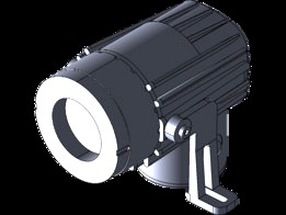
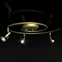
Explosion Proof Sight Glass Light - 100 Watt - 120 Volt or 220/240 Volt
by GrabCAD
Last crawled date: 1 year, 11 months ago
http://www.larsonelectronics.com/p-45298-explosion-proof-sight-glass-light-100-watt-120-volt-or-220240-volt.aspx
Explosion-Proof Small Format Light - UL 844 Listed Class I, Division 1&2, Groups C&D for fitting to sight/light ports and specific area lighting. Approved for wet conditions (UL 1571)
This compact, powerful light can be used in small spaces where operators need Class 1 Division 1 or Class 1 Division 2 lighting.
Made in the USA
The EXPSG-120-100W is excellent for specific area lighting such as instruments, control panels, valve manifolds, walkways, etc. These sturdy lights are constructed of corrosion-resistant aluminum alloy and are moisture-proof as well as explosion-proof (hazardous locations) so they are equally well suited for use in demanding installations indoors and out. Both spot and flood lamp configurations are available for particular applications.
Sight Glass Styles
This light is designed to give glare-free illumination in combination with the following sight glass styles:
• bolt-on circular flanges
• circular weld pad
• visual flow indicators (standard or full-view)
• sanitary clamp connection larger than 3”
• circular threaded assemblies (type MV) larger than 4”
• specific area lighting
UL Hazardous Location Ratings
UL 844 listed for Class I, Division 1 & 2, Groups C and D.
Approved for wet conditions, UL 1571
Temperature Operating Conditions
Temperature range (operating temperature) is referenced to 40°C ambient.
Lamp - 100W Spot halogen lamp with bayonet base and separate reflector.
Lamp Socket - BA 15d Bayonet
Mounting Brackets
Straight mounting brackets are for use on single sight ports from 3” to 6”. Angle (offset) brackets are available for 6” and larger for single light/sight port combinations. Brackets are adaptable to various types of mounting configurations for area lighting.
Installation Instructions
General (See detailed instruction manual)
The light is usually bolted by twin brackets to the sight glass assembly, i.e. to the cover flange of a bolt-on circular sight glass, circular weld-on assembly (type DN28120), visual flow indicator, or mounted for area illumination.
Can be used for the following sight glass sizes and larger:
Bolt-on circular sight window, 2”
Circular weld-on sight window, 3”
Visual flow indicator, 2”
Weld-neck type MV, DN80
Also available are sanitary clamp connections for sizes 1” and larger
Electrical Connection Installation
1. Disconnect main power supply
2. Remove side entrance cover
3. Attach power leads to terminal block
4. Replace cover insuring gasket (o-ring) is in place. Tighten.
5. Connect power
Connections to be in accordance with National Electric Code® Requirements
Lamp Replacement
1. Switch off the light and disconnect power
2. Remove top cover
3. Loosen socket bracket. Removal of the screw is not necessary
4. Remove lamp socket bracket assembly
5. Replace bulb. Use only approved bulb (table 1)
6. Replace lamp socket bracket assembly
7. Tighten bracket screw
8. Reinstall top cover insuring cover gasket (o-ring) is in place.
Tighten.
9. Connect power supply
Parts, Construction and Materials:
• Luminaire body: Corrosion resistant die cast aluminum, G-Al Si 10 Mg
• Lens Holder: Unit of aluminum ring, glass
• Brackets: Die cast Aluminum, G-Al Si 10 Mg
• Weight: 7 lb. (3.2 Kg)
• Gaskets: Silicone rubber o-rings
Similar models
grabcad
free

Explosion Proof LED Compact Light - 10 Watt - 860 Lumen - 120-240V AC - Sight Glass Light
...es used for single light port combinations. brackets are adaptable to various types of mounting configurations for area lighting.
grabcad
free

Explosion Proof LED Compact Light - 10 Watt - 860 Lumen - 12-24 Volt DC - Spot or Flood Light
...es used for single light port combinations. brackets are adaptable to various types of mounting configurations for area lighting.
grabcad
free

Explosion Proof Stack Light With 5 Color - Class 1 Division 1 Class 2 Division 1 - Steady or Strobe
...dy burn or strobing led lamps, as well as high or low voltage configurations. please contact us for special color configurations.
grabcad
free

Explosion Proof Paint Spray Booth Light - Wheeled Dolly Cart - 20,000 Lumens - 4' 4 lamp - 100' Cord
...neries, solvent and cleaning areas, gas processing plants, chemical manufacturing, waste treatment plants, gas processing plants.
grabcad
free

Replacement Mounting Bracket for the Two Lamp EPL-48 and EPL-24 series Explosion Proof Lights
...ght fixtures.
each light fixture requires two (2) surface mount brackets, or (1) pendant mount bracket. choose mount type below.
grabcad
free

Class 1 Division 1 Explosion Proof Stack Light - Signal Traffic Light - Red, Amber, Green, Blue
...dy burn or strobing led lamps, as well as high or low voltage configurations. please contact us for special color configurations.
grabcad
free

Explosion Proof Stack Light With 5 Color - Class 1 Division 1 Class 2 Division 1 - Audible Alarms
...n or strobing led lamps, as well as high or low voltage configurations. please contact us for special color configurations."
grabcad
free

Surface Mount Explosion Proof, Waterproof Fluorescent Lights - T12 Hotbox Configuration
...s to 165 degrees f.
for other lamp optoins please see our epl-48-2l fixture that is approved for paint spray booth applications.
grabcad
free

Explosion Proof Fluorescent Lights for Paint Booths, Oil Rigs, Boats -2 foot - 2 lamp -Multi-voltage
... shows the access caps for changing the bulbs. the second picture shows the bracket at the opposite end of the fluorescent light.
grabcad
free

Explosion Proof Switch for EPL-48-2L Series
...applications: manufacturing, industrial, warehouse, lighting, lighting, wet areas or locations where combustible dust is present.
Volt
turbosquid
$49

LG Volt
... available on turbo squid, the world's leading provider of digital 3d models for visualization, films, television, and games.
turbosquid
$5

LG Volt
... available on turbo squid, the world's leading provider of digital 3d models for visualization, films, television, and games.
3d_ocean
$89
Chevrolet Volt 2011
...com/watch?v=bkrxjnzzuf8 the 3d model was created on real car base. model is created accurately, in real units of measurement, ...
3d_export
$5

9 volts battery
...9 volts battery
3dexport
name:
turbosquid
$25

Volt Steampunk Pistol
...yalty free 3d model volt steampunk pistol for download as 3dm on turbosquid: 3d models for games, architecture, videos. (1485860)
turbosquid
$9

Volt black coin
...id
royalty free 3d model volt black coin for download as max on turbosquid: 3d models for games, architecture, videos. (1634433)
turbosquid
$9

Volt gold coin
...uid
royalty free 3d model volt gold coin for download as max on turbosquid: 3d models for games, architecture, videos. (1634429)
turbosquid
$2

plug 220 volt
...id
royalty free 3d model plug 220 volt for download as blend on turbosquid: 3d models for games, architecture, videos. (1499018)
turbosquid
$20
Volte Gun 2
...royalty free 3d model volte gun 2 for download as max and fbx on turbosquid: 3d models for games, architecture, videos. (1383285)
3d_ocean
$18

Chevrolet Volt rim
...hysically accurate materials. it is separated on parts and they are correctly named. so it is easy to use and modify the model...
Watt
3ddd
$1

Watt & Veke
...watt & veke
3ddd
watt & veke
настольная лампа messina фабрики watt & veke.
3ddd
$1
Watt & veke / Soomkai
...
watt & veke , ротанг
стильная люстра из ротанга soomkai фабрики watt&veke.;
3ddd
free
ROLLE Watt&Veke
...rolle , watt&veke
подвесной светильник rolle watt&veke; из осенней коллекции
turbosquid
$35

We Watt Kiosk
...yalty free 3d model we watt kiosk for download as max and fbx on turbosquid: 3d models for games, architecture, videos. (1461926)
3ddd
$1

Luceplan / OTTO Watt
...условия для любых задач, отдыха или работы. пожалуй, идеальный спутник вашего стола.
дополнительные форматы: max(2010), fbx, 3ds.
3d_export
free
1300 watt subwoofer for cars
...1300 watt subwoofer for cars
3dexport
the model is made to take up space in the house or in the car. power 1300 watts.
3ddd
free
Watt&Veke Spring
...авесной светильник от watt & veke spring, подойдет как для детских, так и для строгих интерьеров, особенно в стилистике лофт.
3d_export
$5

30 watts of power 3D Model
...port
30 watts power 3d model factory electric electrical energy high poly
30 watts of power 3d model karenmodeling 84649 3dexport
3ddd
$1
Watt&Veke Table Lamp
...ble lamp
3ddd
watt&veke
производитель watt&veke;
абажур - vivianne19 h16 ∅19 ∅14
опора для абажура - henning h30 ∅12
3d_export
$5

Substation 110 watts power 3D Model
...odel factory electric electrical energy high poly substation 110
substation 110 watts power 3d model karenmodeling 84650 3dexport
Proof
turbosquid
$6

bullet proof jacket
...el bullet proof jacket for download as 3ds, obj, fbx, and dae on turbosquid: 3d models for games, architecture, videos. (1193147)
turbosquid
$1

Sound Proofing Foam
... sound proofing foam for download as ige, obj, stl, and sldpr on turbosquid: 3d models for games, architecture, videos. (1289027)
turbosquid
$25

Flame proof fibricks_lit
... available on turbo squid, the world's leading provider of digital 3d models for visualization, films, television, and games.
turbosquid
$149

Bullet Proof Vest with molle attachments
... available on turbo squid, the world's leading provider of digital 3d models for visualization, films, television, and games.
3d_export
$40

chevrolet nova ss 70 death proof
...chevrolet nova ss 70 death proof
3dexport
3d_export
$9
of automobile component error proofing system
...cific product defects; the other is to check the products one by one through cheap means to determine whether they are qualified.
turbosquid
$29
Nikon Coolpix AW110 rugged and proof digital camera
... available on turbo squid, the world's leading provider of digital 3d models for visualization, films, television, and games.
turbosquid
$12

Armoured fighting vehicles armoured vehicles with explosion-proof wheels
...ured vehicles with explosion-proof wheels for download as max on turbosquid: 3d models for games, architecture, videos. (1629664)
turbosquid
$27
Fujifilm FinePix XP60 Blue rugged and proof digital camera
... available on turbo squid, the world's leading provider of digital 3d models for visualization, films, television, and games.
turbosquid
$23
Panasonic Lumix DMC-TS5 rugged and proof digital gamera
... available on turbo squid, the world's leading provider of digital 3d models for visualization, films, television, and games.
Explosion
3d_export
$6

explosion
...explosion
3dexport
3 d of explosion
3d_export
$10

explosion
...explosion
3dexport
3d model of explosion for 3d printing
turbosquid
$5

Explosion
...rbosquid
royalty free 3d model explosion for download as max on turbosquid: 3d models for games, architecture, videos. (1202603)
3d_export
$10

Explosion
...explosion
3dexport
turbosquid
$14

Explosion
... available on turbo squid, the world's leading provider of digital 3d models for visualization, films, television, and games.
turbosquid
free

Explosive
... available on turbo squid, the world's leading provider of digital 3d models for visualization, films, television, and games.
3d_ocean
$3
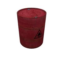
Explosive Barrel
...explosive barrel 3docean barrel decoration explosion explosive industrial low low poly metal object old poly...
3ddd
free
KOLARZ Serie Explosion
... serie explosion , австрия
kolarz serie explosion 0109.118.5.kot. врай. текстуры.
3d_export
$5

atomic bomb explosion
...atomic bomb explosion
3dexport
atomic bomb explosion
turbosquid
$1

explosives pack
...squid
royalty free 3d model explosives pack for download as on turbosquid: 3d models for games, architecture, videos. (1316376)
240
design_connected
$13
Greeny 240
...greeny 240
designconnected
bonaldo greeny 240 computer generated 3d model. designed by carollo, gino.
design_connected
$27

Chat 240
...chat 240
designconnected
de padova chat 240 computer generated 3d model. designed by colombo, carlo.
3d_export
free

Volvo 240
...volvo 240
3dexport
3ddd
$1
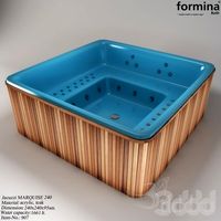
Formina MARQUISE 240
...
formina , ванна , джакузи
formina marquise 240
3ddd
$1
Gaggenau BO-240
...gaggenau bo-240
3ddd
gaggenau , духовой шкаф
gaggenau bo-240 - oven
3ddd
$1

PP 240 chair
...pp , 240 , pp mobler
стул pp240 фирмы pp mobler
design_connected
$29
Rod Sofa 240
...rod sofa 240
designconnected
living divani rod sofa 240 computer generated 3d model. designed by lissoni, piero.
design_connected
$29

Cave Sofa 240
...ignconnected
photo-realistic 3d models of the cave sofa 240 from bonaldo for 3d architectural and interior design presentations.
design_connected
$20
Hoop sofa 240
...hoop sofa 240
designconnected
living divani hoop sofa 240 seating objects computer generated 3d model. designed by arik levy.
design_connected
$29

Lars 240 Low
...onnected
photo-realistic 3d models of the lars 240 low sofa from bonaldo for 3d architectural and interior design presentations.
Sight
3d_export
$10

Sight
...sight
3dexport
sight
3d_ocean
$5
Optic Sight
...t sighting device vision
3d model optic sight by alexrazum vray max materials. higtpoly – max,obj,fbx. lowpoly – max,3ds,obj,fbx.
turbosquid
$3

Sight
... available on turbo squid, the world's leading provider of digital 3d models for visualization, films, television, and games.
turbosquid
$1

sight
... available on turbo squid, the world's leading provider of digital 3d models for visualization, films, television, and games.
3d_export
$5
Sight 3D Model
...sight 3d model
3dexport
sight
sight 3d model strelok00000 59460 3dexport
turbosquid
$10

Sighting scopes
...id
royalty free 3d model sighting scopes for download as dae on turbosquid: 3d models for games, architecture, videos. (1504230)
turbosquid
$1

Sight Glass
...quid
royalty free 3d model sight glass for download as sldpr on turbosquid: 3d models for games, architecture, videos. (1274472)
turbosquid
$9

weapon sight
...ree 3d model weapon sight for download as blend, obj, and fbx on turbosquid: 3d models for games, architecture, videos. (1709288)
turbosquid
$13

Sighting Telescope
...del sighting telescope for download as 3ds, obj, c4d, and fbx on turbosquid: 3d models for games, architecture, videos. (1189172)
turbosquid
$1

Reflex sight
... 3d model reflex sight for download as 3ds, max, obj, and fbx on turbosquid: 3d models for games, architecture, videos. (1315574)
220
design_connected
$29

Lotus 220
...lotus 220
designconnected
arketipo lotus 220 computer generated 3d model. designed by studiomemo.
design_connected
$11

Hulahoop 220
...hulahoop 220
designconnected
bonaldo hulahoop 220 computer generated 3d model. designed by busana, alessandro .
design_connected
$27

Sayonara 220
...sayonara 220
designconnected
bbb emmebonacina sayonara 220 computer generated 3d model. designed by decursu, giorgio.
design_connected
$20

DS-220
...ds-220
designconnected
de sede ds 220 armchairs computer generated 3d model. designed by de sede design-team.
3ddd
$1
Olympus FE - 220
...olympus fe - 220
3ddd
olympus , фотоаппарат
olympus fe - 220
3ddd
$1

Carpenter 220
...carpenter 220
3ddd
диаметр стола 1,6м
turbosquid
$13

Nokia 220
... available on turbo squid, the world's leading provider of digital 3d models for visualization, films, television, and games.
design_connected
$27

Land Sofa 220
...ignconnected
photo-realistic 3d models of the land sofa 220 from bonaldo for 3d architectural and interior design presentations.
design_connected
$9

Zeus table 220
...us table 220
designconnected
poliform zeus table 220 dining tables computer generated 3d model. designed by vincent van duysen.
turbosquid
$50

Excavator JCB 220
...uid
royalty free 3d model excavator jcb 220 for download as on turbosquid: 3d models for games, architecture, videos. (1304620)
120
3ddd
$1

Life 120-120-50
... журнальный , круглый
автор модели: aeroslon
design_connected
$13
XZ3 120
...xz3 120
designconnected
magis xz3 120 computer generated 3d model. designed by van onck, andries & hiroko.
3ddd
$1
diamond so 120
...diamond so 120
3ddd
diamond , morosini
люстра diamond so 120
turbosquid
$10

Table 120
...lty free 3d model table 120 for download as max, obj, and fbx on turbosquid: 3d models for games, architecture, videos. (1503795)
turbosquid
$6

Lamp 120
...alty free 3d model lamp 120 for download as max, obj, and fbx on turbosquid: 3d models for games, architecture, videos. (1500749)
turbosquid
$15

Curtain 120
...e 3d model curtain 120 for download as max, max, fbx, and obj on turbosquid: 3d models for games, architecture, videos. (1618083)
3ddd
$1
Bench 120
...bench 120
3ddd
скамья
bench for two.
turbosquid
$20

Landscape 120
... available on turbo squid, the world's leading provider of digital 3d models for visualization, films, television, and games.
turbosquid
$9
Office 120
... available on turbo squid, the world's leading provider of digital 3d models for visualization, films, television, and games.
3ddd
free

kerasan Bentley 120
... цветок , полотенце
комплект kerasan bentley 120
100
3ddd
$1
Life 100-100-48
...life 100-100-48
3ddd
life , журнальный
автор модели: aeroslon
turbosquid
$9

Landscape 100 X 100 m
... available on turbo squid, the world's leading provider of digital 3d models for visualization, films, television, and games.
3ddd
$1

100 Dollars
...100 dollars
3ddd
100 dollars текстуры в комплекте :-)
3ddd
free

Alexandria 100
...alexandria 100
3ddd
alexandria
мебель для ванной alexandria 100
3d_export
$100

phenom 100
...phenom 100
3dexport
дуже якісна модель приватного літака феном 100
3d_export
$12

100 books
...100 books
3dexport
design_connected
$4

100% Design
...100% design
designconnected
ligne roset 100% design writing desks computer generated 3d model. designed by jeffrey bernett.
3d_export
$5

hyundai h 100
...hyundai h 100
3dexport
hyundai h 100
turbosquid
$2

100 dollars
...bosquid
royalty free 3d model 100 dolars for download as 3ds on turbosquid: 3d models for games, architecture, videos. (1270987)
3d_export
$15

100 ik
...100 ik
3dexport
wat it is biytiful
Glass
archibase_planet
free
Glasses
...glasses
archibase planet
glass wine-glass liqueur-glass
glasses- 3d model for interior 3d visualization.
archibase_planet
free

Glass
...archibase planet
glass cocktail glass tall wine glass martini glass
glass - 3d model (*.gsm+*.3ds) for interior 3d visualization.
archibase_planet
free

Glass
...glass
archibase planet
glass wine-glass glass-ware
glass n030209 - 3d model (*.gsm+*.3ds) for interior 3d visualization.
archibase_planet
free
Glass
...glass
archibase planet
glass-ware glass glass ware
glass n141109 - 3d model (*.gsm+*.3ds) for interior 3d visualization.
3d_ocean
$2
Glass
...liquid container low-poly glass nice glass obj r15 water glass
3d model of a beautiful glass. created the model in cinema 4d r15.
archibase_planet
free
Glass
...glass
archibase planet
glass tall wine glass wine-glass
glass n300514 - 3d model (*.gsm+*.3ds) for interior 3d visualization.
archibase_planet
free

Glass
...glass
archibase planet
glass wine-glass tall wine glass
glass n091210 - 3d model (*.gsm+*.3ds) for interior 3d visualization.
archibase_planet
free
Glass
...glass
archibase planet
glass tall wine glass glass-ware
glass n081011 - 3d model (*.gsm+*.3ds) for interior 3d visualization.
3d_ocean
$9
glasses
...glasses
3docean
glasses
max glasses v-ray
archibase_planet
free
Glass
...glass
archibase planet
glass-ware glass
glass - 3d model (*.gsm+*.3ds) for interior 3d visualization.
Light
archibase_planet
free
Light
...light
archibase planet
lamp lighting light
light - s2 - 3d model for interior 3d visualization.
archibase_planet
free

Light
...light
archibase planet
light luminaire lighting
light l0465 - 3d model (*.gsm+*.3ds) for interior 3d visualization.
3d_export
$5
lighting
...lighting
3dexport
lighting
3d_export
$5

lighting
...lighting
3dexport
lighting in livingroom
turbosquid
$3
Lighting Tree with Lights
...d model lighting tree with lights for download as max and 3ds on turbosquid: 3d models for games, architecture, videos. (1585507)
archibase_planet
free
Light
...light
archibase planet
luster lighting solution
light - s - 3d model for interior 3d visualization.
archibase_planet
free
Light
...light
archibase planet
luster lamp lighting
light 1 - 3d model for interior 3d visualization.
archibase_planet
free
Lights
...lights
archibase planet
surgical lights surgical lamp
surgical lights (floor) - 3d model for interior 3d visualization.
archibase_planet
free
Light
...light
archibase planet
lighting luminaire candlelight
light l0463 - 3d model (*.gsm+*.3ds) for interior 3d visualization.
3d_export
$18
street light-lighting-light-xia bing
...
3dexport
street light-lighting-light-xia bing<br>max 2015 v-ray 3 max 2015<br>textures<br>all files in zip...