Thingiverse
EvoBot robot by afaina
by Thingiverse
Last crawled date: 3 years, 1 month ago
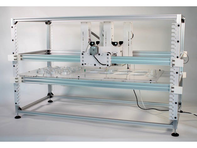
EvoBot: an open source liquid handling robot
This is a low-cost general purpose liquid handling robot that is based on a modular design. Syringe modules (or other modules) can be attached to the head of the robot and each module can move two stepper motor independently (vertical movement and plunger of the syringe). There are electrical connections between the robot and the syringe module, therefore, you do not need to plug any wires to the syringe. Up to 11 modules can be attached at the same time. We built seven robots that are working in different universities around the world (Copenhagen, Bristol, Glasgow, Trento, Prague, Toronto and Karlsruhe).
This robot was designed as part of the Evobliss project, which was funded by the European Union. There are two repositories and one wiki with more information about how to use and build the robot:
Software repository
Hardware repository
Users Wiki
Check the robot in action!
Please, note that this robot needs some skills in order to build it: First, it needs customs printed circuit boards, You need to order them from a manufacturer and solder SMD components on them. Mechanical components are laser cut or 3D printed. Brass inserts are used to avoid tapping. You need also to crimp cables for the connectors of the motors. See below for tips about how to avoid the difficult parts.
Cite: Faina, A., Nejatimoharrami, F., Stoy, K., Theodosiou, P., Taylor, B., & Ieropoulos, I. (2016). EvoBot: An open-source, modular liquid handling robot for nurturing microbial fuel cells. In Artificial Life Conference 2016 (p. 626).
Design
The mechanical design was created in SolidWorks. The 3D printed parts are also exported as STL and the laser cut parts are exported as DXF and PDF. All the files are in the mechanical repository. If you need to modify the design and you do not have access to a SolidWorks license, you can upload the design to Onshape, which is a cloud based CAD program that can import native Solidworks files.
The electronic design was made in DesignSparkPCB, which is free to use. The PCB was exported to Gerber files and can be submitted to manufactures directly. All the designs are in the hardware repository.
A detailed analysis of the costs of its components can be found in the hardware repository. However, a rough estimate of a typical configuration (EvoBot with one actuation layer and one experimental layer) is less than 500$ and each syringe module costs 100$.
Building instructions
The latest building instructions can be found in the EVOBLISS-HARDWARE repository (documentation\building instructions). A complete bill of materials (BOM) is also found there.
Below is only an overview of the assembly process.
Mechanics
The plates of the head and side carriages should be laser cut in POM (recommended) or PLA in 4mm. The height control plates and the module parts should be laser cut in POM on 3mm. If you do not have access to a milling machine or a lase cutter, you can also order these parts online. For example, these shops offer laser cutting services: Pololu, Sculpteo, Ponoko or OSHCUT.
The linear guides of the robot are made of V-slot aluminium profiles and rolling wheels. They can be found in several DIY shops like OpenBuilds or RatRig.
The 3D printed parts can be printed using a FDM printer or they can printed using SLS technology (nylon) in a 3D printing shop such us 3DprintUK or Sculpteo
We also used a lot brass inserts to avoid tapping. Some holes of the plates need to be countersunk, a 90 degrees countersinking tool and a drilling machine is needed.
Electronics
There are two different custom boards that need to be produced: head boards and module board. You need to order the PCBs and the components to assemble them or you could also order them assembled.
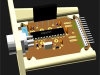
The head board is used to share the electrical connections from the Arduino to the sockets of the modules. This board uses SMD components but it is easy to solder by hand. You only need two per robot.
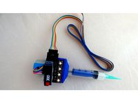
The module board is fixed on the back of the syringe modules and contains the stepper drivers that control the syringes. The stepper drivers have a fine pitch between their legs (0.65mm) and it could be difficult to solder by hand. We recommend you that you order an stencil and use a hot air soldering station. You need one board per module.
If you do not have the skills needed to solder the PCBs, you can contact different manufactures. They can handle all the process (produce the PCBs and stencils, ordering the parts and solder them), but it is more expensive. Try to use some of these shops: Macrofab , Smart-Prototyping or PCB-NG.
Finally an Arduino Mega 2560, a Ramps board and a few Pololu stepper drivers are also needed. Fortunately, they can be bought from almost any shop that sells hardware for 3D printers.
Software
You need to download the software from the software repository. Then, install the Arduino IDE and program the firmware of the Arduino. This process is described in our Wiki.
The control programs are written in Python and we have lots of examples. You can also used the API to write your programms. Everything is well documented in our Wiki.
Acknowledgements
The authors would like to thank E.U. Future and Emergent Technologies who supported this work through EVOBLISS grant no. 611640 and the members of the EVOBLISS consortium who provided input for the requirements and tested the robot.
Questions
Just send me an email
Enjoy it!
Andres
This is a low-cost general purpose liquid handling robot that is based on a modular design. Syringe modules (or other modules) can be attached to the head of the robot and each module can move two stepper motor independently (vertical movement and plunger of the syringe). There are electrical connections between the robot and the syringe module, therefore, you do not need to plug any wires to the syringe. Up to 11 modules can be attached at the same time. We built seven robots that are working in different universities around the world (Copenhagen, Bristol, Glasgow, Trento, Prague, Toronto and Karlsruhe).
This robot was designed as part of the Evobliss project, which was funded by the European Union. There are two repositories and one wiki with more information about how to use and build the robot:
Software repository
Hardware repository
Users Wiki
Check the robot in action!
Please, note that this robot needs some skills in order to build it: First, it needs customs printed circuit boards, You need to order them from a manufacturer and solder SMD components on them. Mechanical components are laser cut or 3D printed. Brass inserts are used to avoid tapping. You need also to crimp cables for the connectors of the motors. See below for tips about how to avoid the difficult parts.
Cite: Faina, A., Nejatimoharrami, F., Stoy, K., Theodosiou, P., Taylor, B., & Ieropoulos, I. (2016). EvoBot: An open-source, modular liquid handling robot for nurturing microbial fuel cells. In Artificial Life Conference 2016 (p. 626).
Design
The mechanical design was created in SolidWorks. The 3D printed parts are also exported as STL and the laser cut parts are exported as DXF and PDF. All the files are in the mechanical repository. If you need to modify the design and you do not have access to a SolidWorks license, you can upload the design to Onshape, which is a cloud based CAD program that can import native Solidworks files.
The electronic design was made in DesignSparkPCB, which is free to use. The PCB was exported to Gerber files and can be submitted to manufactures directly. All the designs are in the hardware repository.
A detailed analysis of the costs of its components can be found in the hardware repository. However, a rough estimate of a typical configuration (EvoBot with one actuation layer and one experimental layer) is less than 500$ and each syringe module costs 100$.
Building instructions
The latest building instructions can be found in the EVOBLISS-HARDWARE repository (documentation\building instructions). A complete bill of materials (BOM) is also found there.
Below is only an overview of the assembly process.
Mechanics
The plates of the head and side carriages should be laser cut in POM (recommended) or PLA in 4mm. The height control plates and the module parts should be laser cut in POM on 3mm. If you do not have access to a milling machine or a lase cutter, you can also order these parts online. For example, these shops offer laser cutting services: Pololu, Sculpteo, Ponoko or OSHCUT.
The linear guides of the robot are made of V-slot aluminium profiles and rolling wheels. They can be found in several DIY shops like OpenBuilds or RatRig.
The 3D printed parts can be printed using a FDM printer or they can printed using SLS technology (nylon) in a 3D printing shop such us 3DprintUK or Sculpteo
We also used a lot brass inserts to avoid tapping. Some holes of the plates need to be countersunk, a 90 degrees countersinking tool and a drilling machine is needed.
Electronics
There are two different custom boards that need to be produced: head boards and module board. You need to order the PCBs and the components to assemble them or you could also order them assembled.
The head board is used to share the electrical connections from the Arduino to the sockets of the modules. This board uses SMD components but it is easy to solder by hand. You only need two per robot.
The module board is fixed on the back of the syringe modules and contains the stepper drivers that control the syringes. The stepper drivers have a fine pitch between their legs (0.65mm) and it could be difficult to solder by hand. We recommend you that you order an stencil and use a hot air soldering station. You need one board per module.
If you do not have the skills needed to solder the PCBs, you can contact different manufactures. They can handle all the process (produce the PCBs and stencils, ordering the parts and solder them), but it is more expensive. Try to use some of these shops: Macrofab , Smart-Prototyping or PCB-NG.
Finally an Arduino Mega 2560, a Ramps board and a few Pololu stepper drivers are also needed. Fortunately, they can be bought from almost any shop that sells hardware for 3D printers.
Software
You need to download the software from the software repository. Then, install the Arduino IDE and program the firmware of the Arduino. This process is described in our Wiki.
The control programs are written in Python and we have lots of examples. You can also used the API to write your programms. Everything is well documented in our Wiki.
Acknowledgements
The authors would like to thank E.U. Future and Emergent Technologies who supported this work through EVOBLISS grant no. 611640 and the members of the EVOBLISS consortium who provided input for the requirements and tested the robot.
Questions
Just send me an email
Enjoy it!
Andres
Similar models
grabcad
free

PCB (Bread Board)
... the small side of most pcbs, you can print multiple of them depending on the size of platform you are using for your 3d printer.
thingiverse
free

A4988 Stepper Motor Driver Spacer.
...ils out of the bottom of the board where they can be soldered.
this part was designed using the freeware version of emachineshop.
thingiverse
free

Laser and ABL Connection Board for CR-10 and other 3D Printer by digitaljunk
...rds the pcb.
to mount the laser module to the cr-10 or ender2 use this https://www.thingiverse.com/thing:2757972
order @ oshpark:
thingiverse
free
Solder Paste Dispenser
...oshpark, and these are the components as a shared project at mouser. and here are zipped gerbers for pcb manufacturing at jlcpcb.
grabcad
free

Simple robotic gripper with ultrasonic sensor for teaching Arduino
...n exercises with arduino.
the gripper components can be 3d printed or laser cut on 3-5mm plywood.
attached pdf with arduino code.
grabcad
free

Simple robotic gripper with ultrasonic sensor for teaching exercises with Arduino
...n exercises with arduino.
the gripper components can be 3d printed or laser cut on 3-5mm plywood.
attached pdf with arduino code.
thingiverse
free

Robot arm carving project
... part so that the screw driver bit could be used as an end effector. we also needed the laser cut part for the motor to drive it.
thingiverse
free
L6208 Stepper Driver PCB and Housing by PolyVinalDistillate
...able moldneg1 or moldneg2 functions)
stepperpcb.dxf - contains the pcb. this is imported into openscad to generate the pcb model.
grabcad
free

Base Arduino Nano
...se arduino nano
grabcad
multipurpose box for arduino nano projects. posts for prototype pcb board that nano can be soldered to.
thingiverse
free

Laser XY Scanner by thingengineer
...s.com/id/low-cost-diy-stepper-motor-laser-xy-scanner-cutter/
video of the laser xy scanner in action:https://youtu.be/hbfobc3svlu
Robot
3d_ocean
$20

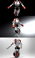
Robot
...robot
3docean
character metal robot robot robotic white
robot model for 3dsmax 2009 and greater
3d_ocean
$45
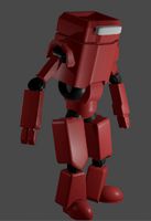
Robot
...robot
3docean
fighing machine robot
a fighting robot from the scrapyard.
3d_ocean
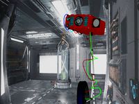
$18
Robot
...robot
3docean
machin robot science fiction
high poly robot.
3d_export
$7
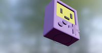
Robot
...robot
3dexport
robot
3d_export
$5
robot
...robot
3dexport
robot
3d_export
free
Robot
...robot
3dexport
robot
turbosquid
$10

Robot/ Alien Robot
...
royalty free 3d model robot/ alien robot for download as max on turbosquid: 3d models for games, architecture, videos. (1442828)
3d_export
$5

robot
...robot
3dexport
robot in blender
3ddd
$1
robot
...robot
3ddd
робот
robot
3ddd
$1

Robot
...robot
3ddd
робот
robot