Thingiverse
ESP12 Pogo Breadboard by bobtidey
by Thingiverse
Last crawled date: 3 years ago
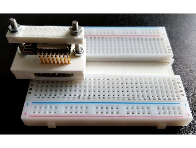
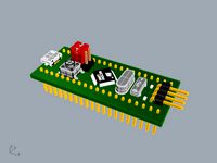
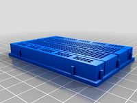
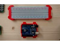
This is an adapter to allow ESP-12 modules to be programmed or developed on a breadboard. It is an alternative version of the one I described at https://www.thingiverse.com/thing:2147460
The previous one fits standard solderless breadboards which have a central gap between the rows of 7.6mm. The width was kept to a minimum and meant that 2 spare holes were still available for connection to each esp-12 pin. This is OK for most applications.
This version uses a solderless breadboard divided into two pieces to allow a bigger gap. The adapter is changed to accommodate this by moving the headers outside the ESP pogo pins. This then allows up to 4 connection points per ESP pin which can be convenient for some uses.
The 3d prints allow spring pins to be used to match the 2mm spacing used on these modules. The pins mate through the holes on the module and allow the module to be just pushed in place. A retaining bar may be used to provide a more secure fit, although for quick programming this may not be needed.
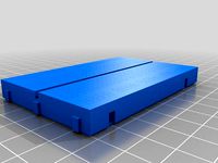
A joiner piece is also included which allows the two parts of the solderless breadboard to be remounted into one piece. The breadboards normally have an adhesive pad at the bottom to make this easy to do.
Parts required are 3d printed parts, 400 point solderless breadboard, 16 spring pogo pins (1mm diameter 16mm long, eBay packets of 100), 2 8way single in line jumper posts (cut off longer strips), 2 M3 30mm countersunk screws and nuts, optional 220uF smd decoupling capacitor.
1) Print off 3d-pieces. Check pogo pins fit into base holes and will go through top plate holes. If necessary clean holes with a 1mm drill.
2) Prepare 14 of the pogo pin by soldering a fine wire about 3.5mm up from base. I used 0.2mm wire got from a multistrand cable. It is important that minimal solder is used to keep the final diameter small to avoid shorts when the pins are assembled.
3) Use slightly thicker wire for the 2 remaining pins which will be the power pins. If using the decoupling capacitor then leave a tail either side.
4) Insert the 8 way headers into the base slot with short side up into the pin cavity side. Do not force as the side wall is deliberately kept thin. Clean up with needle file if needed.
5) Insert pins one at a time into the blind holes in the base and solder the tail onto the header pin. Solder in decoupling capacitor if used.
6) Double check continuity then carefully add epoxy resin around header plugs to secure in place and solidify with narrow sidewall. It is a good idea to tape over the legs underneath to prevent any resin getting onto them.
7) Position pin alignment 3d part over the pins and push down, You can use tweezers to align each pin into the holes as required.
8) insert countersunk screws through both parts and secure with nuts.
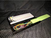
9) Saw breadboard in half down the middle plastic. THis does not expose any connections. Use a reasonably fine saw like a junior hacksaw. It is a good idea to tape over the holes first. Clean up centre with a file.
10) Insert made up pogo module between the two halves to get spacing right. Peel off adhesive layers and stick to joiner.
The previous one fits standard solderless breadboards which have a central gap between the rows of 7.6mm. The width was kept to a minimum and meant that 2 spare holes were still available for connection to each esp-12 pin. This is OK for most applications.
This version uses a solderless breadboard divided into two pieces to allow a bigger gap. The adapter is changed to accommodate this by moving the headers outside the ESP pogo pins. This then allows up to 4 connection points per ESP pin which can be convenient for some uses.
The 3d prints allow spring pins to be used to match the 2mm spacing used on these modules. The pins mate through the holes on the module and allow the module to be just pushed in place. A retaining bar may be used to provide a more secure fit, although for quick programming this may not be needed.
A joiner piece is also included which allows the two parts of the solderless breadboard to be remounted into one piece. The breadboards normally have an adhesive pad at the bottom to make this easy to do.
Parts required are 3d printed parts, 400 point solderless breadboard, 16 spring pogo pins (1mm diameter 16mm long, eBay packets of 100), 2 8way single in line jumper posts (cut off longer strips), 2 M3 30mm countersunk screws and nuts, optional 220uF smd decoupling capacitor.
1) Print off 3d-pieces. Check pogo pins fit into base holes and will go through top plate holes. If necessary clean holes with a 1mm drill.
2) Prepare 14 of the pogo pin by soldering a fine wire about 3.5mm up from base. I used 0.2mm wire got from a multistrand cable. It is important that minimal solder is used to keep the final diameter small to avoid shorts when the pins are assembled.
3) Use slightly thicker wire for the 2 remaining pins which will be the power pins. If using the decoupling capacitor then leave a tail either side.
4) Insert the 8 way headers into the base slot with short side up into the pin cavity side. Do not force as the side wall is deliberately kept thin. Clean up with needle file if needed.
5) Insert pins one at a time into the blind holes in the base and solder the tail onto the header pin. Solder in decoupling capacitor if used.
6) Double check continuity then carefully add epoxy resin around header plugs to secure in place and solidify with narrow sidewall. It is a good idea to tape over the legs underneath to prevent any resin getting onto them.
7) Position pin alignment 3d part over the pins and push down, You can use tweezers to align each pin into the holes as required.
8) insert countersunk screws through both parts and secure with nuts.
9) Saw breadboard in half down the middle plastic. THis does not expose any connections. Use a reasonably fine saw like a junior hacksaw. It is a good idea to tape over the holes first. Clean up centre with a file.
10) Insert made up pogo module between the two halves to get spacing right. Peel off adhesive layers and stick to joiner.
Similar models
thingiverse
free

ESP-12 breadboard adapter by bobtidey
... use tweezers to align each pin into the holes as required.
5) insert countersunk screws through both parts and secure with nuts.
thingiverse
free
Programmer for ESP-12 & ESP-03 modules
...ports both programming and run modes and makes the gpio pins available via a simple header so you can connect it to a breadboard.
thingiverse
free
Wroom32 ESP32 Breadboard adapter by bobtidey
...cessary to slightly bend out the 1.27mm pins to fit the wroom32 module but this does allow a good pressure contact on the module.
thingiverse
free
ESP8266 Pogo Pin carriage and base by benvonhandorf
...ards i had lying around. these are quite small and the dovetail isn't the same size as any other breadboards i own, so ymmv.
thingiverse
free

ESP-12 breadboard adapter by askvictor
... 3short is a 2mm high version, and 3narrow is narrower at the breadboard end so it only takes up the inner row of the breadboard.
thingiverse
free

ESP-07, ESP-12, BW16 breadboard convertor by moononournation
...odule bw16 to breadboard.
this convertor requires two 8 pins 21 mm long pin header, assembly details:https://youtu.be/pgepaknq_om
thingiverse
free

ESP-12E pogo pin programmer
...pogo pins and mounting a serial module to allow programming of a bare esp-12e module. probably works for esp-12f too. and others?
thingiverse
free

ESP-07/ESP-12 adapter by Extroo
...as a programmer. also in the breadboard was a ds18b20 temperature sensor. the socket seems to work fine for me without soldering.
thingiverse
free

ESP-12E Breadboard-Friendly Pin Converter by jellofrog
... about 35 minutes but i developed a rhythm with fishing the wires thru so i imagine things will go quite a bit quicker next time.
grabcad
free

SparkFun PRT-12699 Solderable Breadboard Large
...rge solder-able breadboard also includes real estate for screw terminal connectors and a trace down the center gutter for ground.
Bobtidey
thingiverse
free

Capacitor Meter by bobtidey
...ure for an attiny capacitor meter.
construction details at instructables
https://www.instructables.com/attiny85-capacitor-meter/
thingiverse
free
Bridge test by bobtidey
...the openscad file to make it easier to change dimensions, like the length, width, size of the bridge steps and gap between steps.
thingiverse
free

AutoWater ESP8266 by bobtidey
...ails at https://www.instructables.com/id/battery-powered-plant-watering/
esp software at https://github.com/roberttidey/autowater
thingiverse
free
Array of Pins by bobtidey
... single layer flat base with little tabs so they can be clipped out easily but stabilize it for printing when the pins are small.
thingiverse
free
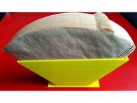
Coffee Filter Paper holder by bobtidey
... coffee filters.
stl is for up to 100 size 4 papers but could be changed in the scad to suit different size papers or quantities.
thingiverse
free
Tiny IR Remote by bobtidey
...at https://github.com/roberttidey/attinyir
instructable at https://www.instructables.com/at-tiny-techniques-in-a-macro-ir-remote/
thingiverse
free

Mathematical Clock by bobtidey
...ficial rim to allow a skirt to be used on the face. see instructions.
a second version of the face has tick marks on the hours.
thingiverse
free

esp8266 clock generator by bobtidey
...e it to conatin a flexible clock / pulse generator as described
https://www.instructables.com/esp8266-clock-and-pulse-generator/
thingiverse
free

Rainbow Dice Box by bobtidey
...ace for the esp-12f controller
full construction details will be on instructables.
https://www.instructables.com/id/rainbow-dice/
thingiverse
free

Digitally controlled power supply by bobtidey
...operation via web browser.
construction is at instructables https://www.instructables.com/digital-controlled-bench-power-supply/
Esp12
thingiverse
free

D1M BLOCK - ESP12 by IOT123
...ing, and 2 off 8 pin 10mm long needle female pin header strip are required for this build.
instructions
code examples
d1m blocks
thingiverse
free

ESP12 Pogo Adapter by pbwns20
...ft, then on the right to prevent heating the plastic too much. let it cool a bit. then turn around in the vise for the other side
thingiverse
free

Prototyping harness for ESP12E by ycomet
...pring pins will work even better.
once that is done you can simply sandwich your esp12e in and secure it with the retainer clips.
thingiverse
free

Socket ESP8266 (ESP12E) by fandres7_7
...ions
based on the work of wdwhite
step file by by_andrey_chirva
see commit details to find the authors of each part.
@fandres7_7
thingiverse
free

CurrentCost ESP12E circuitry box (CC128, EnviR) by saturno
...unication from the energy sensor is received by the esp12.
the code is highly based on the shared project form dontnetdann, here.
thingiverse
free

ESP12 (E/F) Programming Clamp by madtheos
...pport the move to metric, but 2 mm pin pitch certainly does make the esp12 hard to breadboard for programming. hence this design.
thingiverse
free

ESP12 Soldering free connection thing by kungfux
...e
header pins are made from paper clips. paperclips rod diameter is .8mm, so i made holes same diameter, so they fit very tight.
thingiverse
free

ESP12 holder - slim, medium and large by jhawkn8r
...out. the other two should allow for you to house the wires entirely in the box and route them out one of the two holes.
enjoy!
thingiverse
free

ESP12-E Wireless Clock - WS2812b housing by gunkl
...d to enable local echo.
to do
add daylight savings support
make a new lid design that's a little more aesthetically pleasing.
thingiverse
free

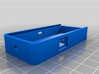
ESP12 project box by bobtidey
...e a good current (80ma) through the led.
the ds18b20 cable parts allow the sensor to be a bit remote and avoid any local warming.
Pogo
3ddd
$1

Joel Escalona / Pogo Table
...joel escalona / pogo table
3ddd
escalona
pogo table by joel escalona
turbosquid
free
pogo stick004.lwo
... available on turbo squid, the world's leading provider of digital 3d models for visualization, films, television, and games.
3d_export
$20
Pogo Stick 3D Model
...go toy jumping jump spring action child outdoor games pole stunt kids pogostick bounce
pogo stick 3d model firdz3d 77099 3dexport
3ddd
$1
Joel Escalona / Pogo Table
... стол
pogo table – это забавное изобретение дизайнера joel escalona, предназначенное для украшения интерьера детских комнат.
3d_export
$10
Pogo Stick v2 3D Model
...toy jumping jump spring action child outdoor games pole stunt kids pogostick bounce
pogo stick v2 3d model firdz3d 90759 3dexport
3d_export
$7

table andersen
...table andersen 3dexport writing desk andersen: dimensions: 1800x750x750 mm<br>laredoute pogo stool: dimensions: ø280 x 470 mm<br>table lamp evoluce satta:...
thingiverse
free

pogo jig essentials by HLCHLCHLC
...ust/scale the vias.
we'd love to know how you make your own pogo jigs. don't hesitate to leave us a comment when you did!
unity_asset_store
$9
Pogo Stick
...elevate your workflow with the pogo stick asset from studiolab. find this & other props options on the unity asset store.
thingiverse
free

Cobra Pogo by SnakeEyes397
... pogo gun
the model is scaled so that 100% matches the dimensions of the original toy. details are optimized for printing at 20%.
3d_sky
free

Joel Escalona / Pogo Table
...joel escalona / pogo table
3dsky
table
pogo table by joel escalona
Breadboard
turbosquid
$15
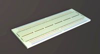
Breadboard
...odel breadboard for download as 3ds, obj, fbx, blend, and dae on turbosquid: 3d models for games, architecture, videos. (1296583)
3d_export
free

breadboard
...ich electronic components and cables can be inserted for the assembly and prototyping of electronic circuits and similar systems.
turbosquid
$49

knife "ZWILLING" and breadboard
... available on turbo squid, the world's leading provider of digital 3d models for visualization, films, television, and games.
3d_export
$29
Parmiggiano Reggiano 3D Model
...italy milk agriculture photorealistic dop hipoly knife cutting board breadboard parmiggiano reggiano 3d model fabelar 31980...
3d_export
$15
Blue Pill STM32
...pill stm32 3dexport stm32 blue pill is a high-performance, breadboard friendly development board with loads of features in a...
thingiverse
free
Breadboard by mitsuhito
...breadboard by mitsuhito
thingiverse
ordinary breadboard
thingiverse
free
Breadboard model by trendigital
...model by trendigital
thingiverse
medium size breadboard model to be used in the design of a breadboard holder. not for printing.
thingiverse
free
BreadBoard Holder by Gombooc
...breadboard holder by gombooc
thingiverse
breadboard holder
thingiverse
free

Breadboard stand by MT1
...breadboard stand by mt1
thingiverse
stand for the breadboard.
thingiverse
free
Modular breadboard by max1600
...modular breadboard by max1600
thingiverse
modular breadboard