Thingiverse
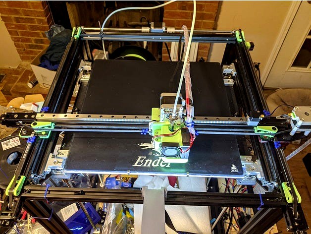
Ender 5 Plus Linear Rail Conversion by GiulianoM
by Thingiverse
Last crawled date: 3 years, 3 months ago
Summary
THIS DESIGN IS NOW COMPLETE
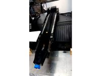
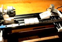
This is a conversion kit for the Ender 5 Plus to MGN12 Linear Rails, 450mm long x 3 and 3 x MGN12H linear blocks.
I highly recommend these MGN12 rails from RobotDigg:
https://www.robotdigg.com/product/766/Quality-440C-SUS-MGN12-linear-rail-with-carriage
3 x SS_MGN12-1H-450
You will also need M3 T-nuts, I recommend slide-in 20-series M3 nuts like these:
https://www.ebay.com/itm/100X-M3-M4-M5-M6-T-Block-Square-nuts-T-Sliding-Hammer-Nut-Aluminum-Profile/274057650436
Get a pack of 100, you will need a bunch of them.
You will also need a bunch of M3 12mm long screws, button head or normal socket head cap screw.
Each rail has 18 mounting holes, so you will need 54 screws and 54 T-nuts.
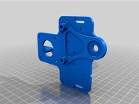
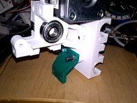
The adapter plate for the MicroSwiss Direct Drive extruder adapts the back of the plate to join to the MGN12H block.
This adapter plate requires modifications to the back of the MicroSwiss plate!
You will need to take a 3/8" or 9.5mm drill bit and drill out the two wheel mounting studs on the back of the plate, but only drill until the surface is flat, don't drill through the plate.
The stock Ender 5 Adapter plate shouldn't need any modifications.
There is a printable drilling rig part in the parts list to attach to the front of the MicroSwiss extruder to provide a flat surface to drill against.
This design uses "OpenBuilds" style M5 low-profile screws of various lengths:
https://openbuildspartstore.com/low-profile-screws-m5-10-pack/
They're somewhat expensive, but if you search eBay for "M5 Low Profile hex screw" you can find less expensive ones:
https://www.ebay.com/itm/Precision-M5-Low-Profile-Hex-Screws-Black-3D-6-8-10-12-15-20-25-30-35-40mm/133296439988
I also used M3 button head socket cap screws, which have a shorter head than the normal socket head cap screw.
I recommend Albany County Fasteners:
https://www.albanycountyfasteners.com/metric-socket-cap-screws/693.htm
Parts List
The following is the printed parts list and hardware bits required.
X-Carriage
Print:
1 x X-Carriage MGN12 Block.stl
1 x X-Carriage_Microswiss_DD_Adapter.stl
OR
1 x Stock_Ender5+_Hotend_Adapter.stl
Suggested infill of 50-75%.
Hardware:
3 x M5 30mm Low-Profile screws.
2 x M5 8mm Low-Profile screws.
1 x M5 12mm Low-Profile screw.
4 x M5 Hex Nuts
4 x M3 12mm button head cap screws, for the MGN12H mounting block.
Y-Axis Blocks
Print:
1 x Y-Axis Idler Horizontal Block.stl
1 x Y-Axis Motor Horizontal Block.stl
2 x Y-Axis Vertical Block.stl
Suggested infill of 50-75%.
Hardware:
4 x M5 30mm Low-Profile screws.
4 x M5 Hex Nuts
4 x M5 10mm Low-Profile screws.
Idler Bearing Blocks
The Idler Bearing blocks are designed to hold the Gates 2GT 20T toothed 6mm idlers, the ones 15mm in diameter, 6mm wide for 6mm belts.
https://www.filastruder.com/collections/hardware/products/gates-2gt-idler
The design requires 6 of them.
I also highly recommend getting Gates 2GT belt as well - I ordered 4 meters and had about 2 feet left over.
Print:
6 x Idler Bearing.stl
Hardware:
6 x M5 20mm Low-Profile screws.
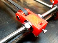
Alignment Blocks
These parts are used for aligning the MGN12 rails to the aluminum extrusion during assembly, and they are removed after.
Print:
6 x Y-Axis_Alignment_Block.stl
6 x X-Axis_Alignment_Block.stl
Hardware:
12 x M5 10mm Low-Profile screws.
12 x M5 T-Nut
X-Axis Motor Standoffs
The design of the Y-axis bearing blocks interferes with the normal position of the X-axis stepper motor, so you must flip it upside down on top of the gantry with these standoffs.
Note that flipping the stepper motor also requires that you flip the X-axis stepper direction in your firmware, or swap the motor wiring pins around to flip the direction.
The pulley on the stepper motor must also be flipped upside down, with the grub screw portion of the pulley facing down.
Print:
4 x Motor Standoff.stl
Infill: 100%
Hardware:
4 x M3 25mm screws.
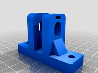
Limit Switch Holder
The Limit Switch for the X axis will need to be relocated on top of the extrusion.
It should be installed at the end of the linear rail, to prevent the MGN12 linear block from sliding off the end.
You may have to adjust the position of the linear rail to get the X-axis endstop location correct. I would suggest taking a sharpie and marking where the factory switch is located.
The Y-axis Endstop Switch should be able to remain in the factory location.
Print:
1 x Limit Switch Holder.stl
Hardware:
1 x M5 10mm Low-Profile screw.
1 x M5 T-Nut
Assembly Guide
X-Axis Motor
You will also need to flip the direction of your X-axis in firmware, or re-wire the stepper motor wires to flip the direction.
Remove the X-Axis Motor and the cover.
Remove the pulley from the X-Axis Motor and reinstall it upside down.
Place 4 x Motor Standoff parts on top of the plate, and place the motor on top of the standoffs, with the shaft and pulley facing down.
Insert 4 x M3 25mm screws through the motor mounting holes in the bottom of the plate, up through the standoffs, and into the motor.
Y-Axis Blocks
The Y-Axis blocks mount to the underside of the X-Axis ends, where the wheels would normally go.
Make note of the difference between the Motor End and Idler End Horizontal blocks, they are different and not interchangeable. The vertical blocks are the same.
Remove the wheels and hardware from the X-Axis ends.
Assemble each horizontal block with a vertical block, using 2 x M5 30mm low-profile screws and 2 x M5 Hex Nuts.
Insert the peg on the horizontal blocks into the bottom side of the X-Axis metal plates. The vertical blocks should be on the outside.
Screw 2 x M5 10mm screws in through the top side of each metal plate into the plastic of the horizontal block.
X-Axis Linear Rail
The X-Axis linear rail mounts to the top side of the rail, with the MGN12 bearing block facing up.
Be very careful with handling the rails, and make sure that the bearing block does not slide off!
Remove the belt idler bearing assembly from the end of the X-axis extrusion.
Slide in 18 x M3 T-Nuts, if you got the slide-in kind. If you got the twist-lock kind nuts, skip this.
Insert 18 x M3 12mm screws into the holes in the rails.
Drive the screws into the T-Nuts in the extrusion, but do not tighten them fully.
Attach the X-Axis Alignment Blocks to the front and back of the rail so that the lip on the part presses up against the linear rail to center it.
Tighten the screws in the linear rail.
Remove the Alignment Blocks.
Y-Axis Linear Rails
The Y-Axis Linear Rails are installed on the outside of the 2040 extrusion on the left and right sides, in the top slot, with the linear block facing outside to the left and right.
The Y-Axis Linear rails do not go on top of the 2040 extrusion.
Remove the Y-axis Idler pulley assemblies from the front of the printer.
Slide in 18 x M3 T-Nuts in the side of the 2040 extrusion, in the top slot - facing right/left.
Insert 18 x M3 12mm screws into the holes in the linear rail.
Drive the screws into the T-Nuts in the extrusion, but do not tighten them fully.
Attach 3 x Y-Axis Alignment Blocks in the slot underneath the T-Nuts, with the arrow on the alignment blocks facing up. Put one at each end of the rail, and one in the middle. The edge of the blocks should be supporting the rail above it.
Tighten the screws in the linear rail.
Remove the Alignment Blocks.
Attaching the X-Axis to the Y-Axis
At this point, you will take the entire assembled X-Axis with their adapter blocks, and drop them on top of the MGN12 blocks on the outside of the printer.
You will adjust the tension on the rails by tightening the screws on the Motor End fully, and tightening the screws on the Idler End.. less fully.
Take the assembled X-Axis, and slide the vertical mounting blocks over the MGN12 blocks on the Y-Axis rails. It should be a be a tight fit.
On the Motor End of the X-Axis, insert 4 x M3 12mm screws through the vertical mounting block into the threaded holes in the MGN12 block.
On the Motor End of the X-Axis, tighten the screws in an X-fashion until they are tight with roughly the same tension on all 4 screws.
On the Idler End of the X-Axis, insert 4 x M3 12mm screws.
On the Idler End of the X-Axis, tighten the screws in an X-fashion - but NOT too tight!
Move the Y-axis back and forth on the rails, pushing from the center of the rail.
The rail should move with very little friction or noise.
If there's too much friction or noise, loosen the screws on the Idler End a bit until the friction goes away.
X-Carriage Assembly
If you're using the MicroSwiss Extruder, print out the drilling jig part first and drill off the top two wheel studs on the back of the extruder plate until the surface is flat. Use a small needle file or sandpaper to flatten any edges.
Remove all the wheels and hardware from the hotend.
Cut out the holes in the adapter block.
Insert the 2 x M5 8mm Low-Profile screws into the top two holes in the back of the adapter plate, where the top two wheels would go.
Insert 1 x M5 Nut in the adapter plate where the bottom wheel would go.
Attach the X-Carriage MGN12 Block to the X-Carriage_Microswiss_DD_Adapter block using the 3 x M5 30mm Low-Profile screws and 3 x M5 Hex Nuts.
Attach the front of the adapter block to the back of the MicroSwiss extruder plate, using the 2 x M5 8mm screws threading into the upper wheel mounts.
Insert the M5 12mm screw in through the front of the MicroSwiss Extruder plate where the bottom wheel would go, and tighten into the nut in the back.
Mount the assembly to the linear rail block using the 4 x M3 12mm button head screws. The top of the screws must be flush with the top of the block, they shouldn't protrude or they'll interfere with the extruder stepper motor.
Alignment Calibration
Once the printer is fully re-assembled with the linear rails, you may find that the X-axis may not be perfectly perpendicular (square) to the Y-axis. This is also called "skew".
The first part you should print is a calibration square, I recommend this one:
YACS (Yet Another Calibration Square)https://www.thingiverse.com/thing:2563185
Print it out, and use a digital caliper to measure the distance across the diagonal flats.
They should measure the same, within a few tenths of a mm.
If they do not measure the same, then your X-axis is not square with the Y-axis.
You can correct this by either:
Physically adjust one of the pulleys on the Y-axis motor end to move one end of the X-Axis end farther or closer.
Enable "Skew Compensation" in your printer's firmware to correct for the physical alignment.
For Marlin firmware, you will need to update your configuration.h file to enable Skew Compensation.
Video to watch: https://www.youtube.com/watch?v=YfAb5IaHDSo
I would recommend these steps:
Print off an YACS X/Y calibration part.
Measure the diagonal distances.
If the differences are ~2mm or less, then set up the Skew Compensation in firmware.
If the differences are more than 3-5mm, then adjust the pulleys on the Y-axis to compensate, then print another YACS X/Y calibration part.
Repeat above until satisfied.
THIS DESIGN IS NOW COMPLETE
This is a conversion kit for the Ender 5 Plus to MGN12 Linear Rails, 450mm long x 3 and 3 x MGN12H linear blocks.
I highly recommend these MGN12 rails from RobotDigg:
https://www.robotdigg.com/product/766/Quality-440C-SUS-MGN12-linear-rail-with-carriage
3 x SS_MGN12-1H-450
You will also need M3 T-nuts, I recommend slide-in 20-series M3 nuts like these:
https://www.ebay.com/itm/100X-M3-M4-M5-M6-T-Block-Square-nuts-T-Sliding-Hammer-Nut-Aluminum-Profile/274057650436
Get a pack of 100, you will need a bunch of them.
You will also need a bunch of M3 12mm long screws, button head or normal socket head cap screw.
Each rail has 18 mounting holes, so you will need 54 screws and 54 T-nuts.
The adapter plate for the MicroSwiss Direct Drive extruder adapts the back of the plate to join to the MGN12H block.
This adapter plate requires modifications to the back of the MicroSwiss plate!
You will need to take a 3/8" or 9.5mm drill bit and drill out the two wheel mounting studs on the back of the plate, but only drill until the surface is flat, don't drill through the plate.
The stock Ender 5 Adapter plate shouldn't need any modifications.
There is a printable drilling rig part in the parts list to attach to the front of the MicroSwiss extruder to provide a flat surface to drill against.
This design uses "OpenBuilds" style M5 low-profile screws of various lengths:
https://openbuildspartstore.com/low-profile-screws-m5-10-pack/
They're somewhat expensive, but if you search eBay for "M5 Low Profile hex screw" you can find less expensive ones:
https://www.ebay.com/itm/Precision-M5-Low-Profile-Hex-Screws-Black-3D-6-8-10-12-15-20-25-30-35-40mm/133296439988
I also used M3 button head socket cap screws, which have a shorter head than the normal socket head cap screw.
I recommend Albany County Fasteners:
https://www.albanycountyfasteners.com/metric-socket-cap-screws/693.htm
Parts List
The following is the printed parts list and hardware bits required.
X-Carriage
Print:
1 x X-Carriage MGN12 Block.stl
1 x X-Carriage_Microswiss_DD_Adapter.stl
OR
1 x Stock_Ender5+_Hotend_Adapter.stl
Suggested infill of 50-75%.
Hardware:
3 x M5 30mm Low-Profile screws.
2 x M5 8mm Low-Profile screws.
1 x M5 12mm Low-Profile screw.
4 x M5 Hex Nuts
4 x M3 12mm button head cap screws, for the MGN12H mounting block.
Y-Axis Blocks
Print:
1 x Y-Axis Idler Horizontal Block.stl
1 x Y-Axis Motor Horizontal Block.stl
2 x Y-Axis Vertical Block.stl
Suggested infill of 50-75%.
Hardware:
4 x M5 30mm Low-Profile screws.
4 x M5 Hex Nuts
4 x M5 10mm Low-Profile screws.
Idler Bearing Blocks
The Idler Bearing blocks are designed to hold the Gates 2GT 20T toothed 6mm idlers, the ones 15mm in diameter, 6mm wide for 6mm belts.
https://www.filastruder.com/collections/hardware/products/gates-2gt-idler
The design requires 6 of them.
I also highly recommend getting Gates 2GT belt as well - I ordered 4 meters and had about 2 feet left over.
Print:
6 x Idler Bearing.stl
Hardware:
6 x M5 20mm Low-Profile screws.
Alignment Blocks
These parts are used for aligning the MGN12 rails to the aluminum extrusion during assembly, and they are removed after.
Print:
6 x Y-Axis_Alignment_Block.stl
6 x X-Axis_Alignment_Block.stl
Hardware:
12 x M5 10mm Low-Profile screws.
12 x M5 T-Nut
X-Axis Motor Standoffs
The design of the Y-axis bearing blocks interferes with the normal position of the X-axis stepper motor, so you must flip it upside down on top of the gantry with these standoffs.
Note that flipping the stepper motor also requires that you flip the X-axis stepper direction in your firmware, or swap the motor wiring pins around to flip the direction.
The pulley on the stepper motor must also be flipped upside down, with the grub screw portion of the pulley facing down.
Print:
4 x Motor Standoff.stl
Infill: 100%
Hardware:
4 x M3 25mm screws.
Limit Switch Holder
The Limit Switch for the X axis will need to be relocated on top of the extrusion.
It should be installed at the end of the linear rail, to prevent the MGN12 linear block from sliding off the end.
You may have to adjust the position of the linear rail to get the X-axis endstop location correct. I would suggest taking a sharpie and marking where the factory switch is located.
The Y-axis Endstop Switch should be able to remain in the factory location.
Print:
1 x Limit Switch Holder.stl
Hardware:
1 x M5 10mm Low-Profile screw.
1 x M5 T-Nut
Assembly Guide
X-Axis Motor
You will also need to flip the direction of your X-axis in firmware, or re-wire the stepper motor wires to flip the direction.
Remove the X-Axis Motor and the cover.
Remove the pulley from the X-Axis Motor and reinstall it upside down.
Place 4 x Motor Standoff parts on top of the plate, and place the motor on top of the standoffs, with the shaft and pulley facing down.
Insert 4 x M3 25mm screws through the motor mounting holes in the bottom of the plate, up through the standoffs, and into the motor.
Y-Axis Blocks
The Y-Axis blocks mount to the underside of the X-Axis ends, where the wheels would normally go.
Make note of the difference between the Motor End and Idler End Horizontal blocks, they are different and not interchangeable. The vertical blocks are the same.
Remove the wheels and hardware from the X-Axis ends.
Assemble each horizontal block with a vertical block, using 2 x M5 30mm low-profile screws and 2 x M5 Hex Nuts.
Insert the peg on the horizontal blocks into the bottom side of the X-Axis metal plates. The vertical blocks should be on the outside.
Screw 2 x M5 10mm screws in through the top side of each metal plate into the plastic of the horizontal block.
X-Axis Linear Rail
The X-Axis linear rail mounts to the top side of the rail, with the MGN12 bearing block facing up.
Be very careful with handling the rails, and make sure that the bearing block does not slide off!
Remove the belt idler bearing assembly from the end of the X-axis extrusion.
Slide in 18 x M3 T-Nuts, if you got the slide-in kind. If you got the twist-lock kind nuts, skip this.
Insert 18 x M3 12mm screws into the holes in the rails.
Drive the screws into the T-Nuts in the extrusion, but do not tighten them fully.
Attach the X-Axis Alignment Blocks to the front and back of the rail so that the lip on the part presses up against the linear rail to center it.
Tighten the screws in the linear rail.
Remove the Alignment Blocks.
Y-Axis Linear Rails
The Y-Axis Linear Rails are installed on the outside of the 2040 extrusion on the left and right sides, in the top slot, with the linear block facing outside to the left and right.
The Y-Axis Linear rails do not go on top of the 2040 extrusion.
Remove the Y-axis Idler pulley assemblies from the front of the printer.
Slide in 18 x M3 T-Nuts in the side of the 2040 extrusion, in the top slot - facing right/left.
Insert 18 x M3 12mm screws into the holes in the linear rail.
Drive the screws into the T-Nuts in the extrusion, but do not tighten them fully.
Attach 3 x Y-Axis Alignment Blocks in the slot underneath the T-Nuts, with the arrow on the alignment blocks facing up. Put one at each end of the rail, and one in the middle. The edge of the blocks should be supporting the rail above it.
Tighten the screws in the linear rail.
Remove the Alignment Blocks.
Attaching the X-Axis to the Y-Axis
At this point, you will take the entire assembled X-Axis with their adapter blocks, and drop them on top of the MGN12 blocks on the outside of the printer.
You will adjust the tension on the rails by tightening the screws on the Motor End fully, and tightening the screws on the Idler End.. less fully.
Take the assembled X-Axis, and slide the vertical mounting blocks over the MGN12 blocks on the Y-Axis rails. It should be a be a tight fit.
On the Motor End of the X-Axis, insert 4 x M3 12mm screws through the vertical mounting block into the threaded holes in the MGN12 block.
On the Motor End of the X-Axis, tighten the screws in an X-fashion until they are tight with roughly the same tension on all 4 screws.
On the Idler End of the X-Axis, insert 4 x M3 12mm screws.
On the Idler End of the X-Axis, tighten the screws in an X-fashion - but NOT too tight!
Move the Y-axis back and forth on the rails, pushing from the center of the rail.
The rail should move with very little friction or noise.
If there's too much friction or noise, loosen the screws on the Idler End a bit until the friction goes away.
X-Carriage Assembly
If you're using the MicroSwiss Extruder, print out the drilling jig part first and drill off the top two wheel studs on the back of the extruder plate until the surface is flat. Use a small needle file or sandpaper to flatten any edges.
Remove all the wheels and hardware from the hotend.
Cut out the holes in the adapter block.
Insert the 2 x M5 8mm Low-Profile screws into the top two holes in the back of the adapter plate, where the top two wheels would go.
Insert 1 x M5 Nut in the adapter plate where the bottom wheel would go.
Attach the X-Carriage MGN12 Block to the X-Carriage_Microswiss_DD_Adapter block using the 3 x M5 30mm Low-Profile screws and 3 x M5 Hex Nuts.
Attach the front of the adapter block to the back of the MicroSwiss extruder plate, using the 2 x M5 8mm screws threading into the upper wheel mounts.
Insert the M5 12mm screw in through the front of the MicroSwiss Extruder plate where the bottom wheel would go, and tighten into the nut in the back.
Mount the assembly to the linear rail block using the 4 x M3 12mm button head screws. The top of the screws must be flush with the top of the block, they shouldn't protrude or they'll interfere with the extruder stepper motor.
Alignment Calibration
Once the printer is fully re-assembled with the linear rails, you may find that the X-axis may not be perfectly perpendicular (square) to the Y-axis. This is also called "skew".
The first part you should print is a calibration square, I recommend this one:
YACS (Yet Another Calibration Square)https://www.thingiverse.com/thing:2563185
Print it out, and use a digital caliper to measure the distance across the diagonal flats.
They should measure the same, within a few tenths of a mm.
If they do not measure the same, then your X-axis is not square with the Y-axis.
You can correct this by either:
Physically adjust one of the pulleys on the Y-axis motor end to move one end of the X-Axis end farther or closer.
Enable "Skew Compensation" in your printer's firmware to correct for the physical alignment.
For Marlin firmware, you will need to update your configuration.h file to enable Skew Compensation.
Video to watch: https://www.youtube.com/watch?v=YfAb5IaHDSo
I would recommend these steps:
Print off an YACS X/Y calibration part.
Measure the diagonal distances.
If the differences are ~2mm or less, then set up the Skew Compensation in firmware.
If the differences are more than 3-5mm, then adjust the pulleys on the Y-axis to compensate, then print another YACS X/Y calibration part.
Repeat above until satisfied.
Similar models
thingiverse
free

CR10s Pro Linear Rail Mod by Bozo76
...m rails
profile 20x20x50 min 3pce
m3 t-nuts
m3x8 hex screws
m5 hex screws to attache the 20x20 profiles on the x-gantry
m5 t-nuts
thingiverse
free
Ender 3 V2 Y-Axis dual rail bracket by sr6imp
...ignment here on thingiverse, you probably have to cut them in half or half print them to use them on the installed 40x40 profile.
thingiverse
free

MGN12 Alignment Block by snicker
...near rails on a 20mm aluminum extrusion. print two or more and snap them on the mgn12 and the rail and tighten your m3 cap bolts.
thingiverse
free

Ender 3 V2 Linear Rail Direct Drive X-Axis Conversion V1 by VonTaube
...
crimp belt and tension
see ender 3 v2 direct drive link below for extruder install infohttps://www.thingiverse.com/thing:4621486
thingiverse
free
Hictop 3dp11 Adjustable Y Idler Mount by SaberShip
...rts:
x1 stock 608zz idler bearing
x1 stock m3 bolt and nut
x2 stock m5 bolts
x2 stock m5 t-slot nuts
x2 m3 x 10 screws
x2 m3 nuts
thingiverse
free

Y-Axis Linear Bearing Mod MGN12H for Ender 3 V2 by ngungbi
... then tighten the rail screw at the rear.
make sure the carriage can move freely with very little resistance.
reassemble the bed.
thingiverse
free
prusa i3 Y idler with belt tightener. by liusega
...ith belt tightener. by liusega
thingiverse
prusa i3 y idler with belt tightener
m5x20 screw x1
m5 nut
m3x15 screw x1
m3 nut x1
thingiverse
free

Tevo Flash Linear Mod (only with MGN12H) by GMein
...n't need to change anything else on the printer.
it should be easy to see what are each part is for. otherwise let me know ;)
thingiverse
free

Anycubic Mega Zero X-Axis Linear Rail by foureight84
...d be fine. don't over tighten and don't use screws longer than 8mm. 6mm might work as well.
7) rerun z-offset calibration
thingiverse
free
wood tool grip linear rail mount by kurakxd
...rning tool 12mm diameter.
project for my mini lathe
required 8x m3x12mm 8x m3 nut, 1x m5 bolt for screw tighten clamp 1x m5 nut
Giulianom
thingiverse
free

Lumia 640 Mount by GiulianoM
...l shrink to the correct size. abs will also more likely resist high temperatures in a car, so i wouldn't recommend using pla.
thingiverse
free
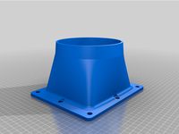
Dust Collector Blower to 6" Duct by GiulianoM
...l fit in sdr pipes of slightly varying diameters.
used for venting the blower outside or otherwise into some other 6" input.
thingiverse
free
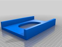
4" x 6" Oval Hole Template by GiulianoM
... 7", and the distance between the two walls is 6.04".
clamp it down over a 6" board and the oval will be centered.
thingiverse
free
MicroSwiss Ender 5 Plus Direct Drive Plate by GiulianoM
...ve-extruder-for-creality-ender-5
i am using the stl to design a cooling shroud since there are extra mounting holes on the plate.
thingiverse
free

Dial Indicator Mount for MGN12H Linear Block by GiulianoM
...m3 10mm screws for mounting the adapter block to the mgn12h carriage.
1 x m3 screw, 10-15mm long for securing the dial indicator.
thingiverse
free

Arducam 5MP OV5647 Camera Mount by GiulianoM
...e should come with the camera kit.
if not, you'll need 4 x m2 15mm screws and 4 x m2 nuts.
m2 - 2mm screws, not m2.5 - 2.5mm.
thingiverse
free

LM8LUU Bearing Blocks for Prusa Y-Axis by GiulianoM
...the blocks to the y-carriage. 20mm are long enough if your plate is threaded - use 25-30mm with nuts if yours is drilled through.
thingiverse
free

i3 Z-Ends for LM8LUU and 8mm Anti-Backlash Nut by GiulianoM
...44
these are the z-end parts that correspond with the x-ends i designed:http://www.thingiverse.com/thing:1060956
work in progress
thingiverse
free
Mini Height Differential IR Sensor Board Mount for E3D v6 / Prusa i3 Rework by GiulianoM
...t onto the bottom two m4 bolts for the "e3d v6 compact extruder for i3 rework":
http://www.thingiverse.com/thing:725082
thingiverse
free

Dual Melzi Box for RepRapPro Tricolor Mendel by GiulianoM
...clips on the top piece snapped off really easily, so i modified the top to make the clip walls a little thicker (2.0mm vs 1.5mm).
Conversion
3ddd
$1

Conversation Seat
...шетка
the conversation seat made in englandhttp://www.squintlimited.com/products/the_conversation_seat/gold
+ max 2011
3d_export
$10

Converse 3D Model
...converse 3d model
3dexport
converse shoe pc unix mac
converse 3d model electropainter17075 38067 3dexport
turbosquid
$100

converse-shoe
...quid
royalty free 3d model converse-shoe for download as c4d on turbosquid: 3d models for games, architecture, videos. (1398427)
turbosquid
$10

Conversation Furniture
... available on turbo squid, the world's leading provider of digital 3d models for visualization, films, television, and games.
turbosquid
$7

Converse Allstars
... available on turbo squid, the world's leading provider of digital 3d models for visualization, films, television, and games.
design_connected
$16

Conversation Club Chair
...conversation club chair
designconnected
donghia conversation club chair chairs computer generated 3d model. designed by n/a.
design_connected
$27

Hemicycle Conversation Chair
...rsation chair
designconnected
ligne roset hemicycle conversation chair computer generated 3d model. designed by nigro, philippe.
3d_export
$24

Converse keds 3D Model
...converse keds 3d model
3dexport
converse all star ked shoe clothes sports
converse keds 3d model vermi1ion 26201 3dexport
3ddd
$1

Converse All-Star Shoes
...converse all-star shoes
3ddd
кеды , обувь
converse all-star shoes
design_connected
$18

CONVERSE Jack Purcell Sneakers
...converse jack purcell sneakers
designconnected
converse jack purcell sneakers computer generated 3d model.
Linear
3ddd
$1
Linear Diffusers
...linear diffusers
3ddd
диффузор
set of linear diffusers for ceiling.
design_connected
$27
Linear Sofa
...linear sofa
designconnected
scp linear sofa computer generated 3d model.
design_connected
$18

Atlantis linear
...atlantis linear
designconnected
terzani atlantis linear pendant lights computer generated 3d model. designed by barlas baylar.
3d_export
$5
light linear unit
...light linear unit
3dexport
light linear unit
turbosquid
$5
Linear Actuator
...
royalty free 3d model linear actuator for download as blend on turbosquid: 3d models for games, architecture, videos. (1589061)
turbosquid
$29
Linear panel
...oyalty free 3d model linear panel for download as max and obj on turbosquid: 3d models for games, architecture, videos. (1391254)
turbosquid
$12
Linear Chandelier
...y free 3d model linear chandelier for download as max and obj on turbosquid: 3d models for games, architecture, videos. (1574289)
turbosquid
$10

Grohe Lineare
... available on turbo squid, the world's leading provider of digital 3d models for visualization, films, television, and games.
turbosquid
$10

Linear Axis
... available on turbo squid, the world's leading provider of digital 3d models for visualization, films, television, and games.
3d_export
$5
Linear Unit 3D Model
...linear unit 3d model
3dexport
linear unit force torque velocity
linear unit 3d model fau 71218 3dexport
Ender
3ddd
$1
Enders / Elegance
...enders / elegance
3ddd
обогреватель
уличный газовый обогреватель enders elegance
высота: 2200 мм
3d_export
free
ender 3 frame cavity covers
... of the creality ender 3 - makes it look a bit more attractive it just slides into the open channels of the aluminium framework
turbosquid
$1
pen support for ender 3
...y free 3d model pen support for ender 3 for download as blend on turbosquid: 3d models for games, architecture, videos. (1611282)
3d_ocean
$9
Ender Dragon Minecraft
...ojang obj poly videogames
ender dragon minecraft created with cinema 4d r15 formats included: max 2013 – fbx 2012 – c4d r15 – obj
3d_export
free
Creality ender enclosure webcam mount
...e creality enclosure. sure is better than a tripod. change it up if it helps. i printed pla with 50% infill on my dd ender 3 pro.
3d_export
free
ender 3 enclosure corners
...er corners and 4 upper corners, using 25mmx25mm angled aluminium pieces that gets covered on inside of the frame with plexiglass
3d_export
free
ender 3 3d print bed clips
...ed + normal aluminium bed frame of the creality ender 3 = 6mm (b) these clips are designed for glass plate + aluminium bed = 4mm
3d_export
$5
GRUMPY CAT
...grumpy cat 3dexport grumpy cat to print in ender ...
3d_export
$5

Logs fire
...with one multi material for corona and vray r ender. albedo, normal, uvmap, roughness format jpg 4096x4096 models:...
3d_export
$42

excavator
...is the original size. 0.12 mm printing surface creality ender5 ...
Plus
turbosquid
$2
plus-plus puzzle and lego
...d model plus-plus puzzle and lego for download as stl and obj on turbosquid: 3d models for games, architecture, videos. (1662633)
3ddd
$1
Стенка Plus
...стенка plus
3ddd
plus , модная мебель
фабрика "модная мебель", модель plus
3ddd
$1

Спальня METIS plus
... hulsta , metis , спальня
спальня metis plus
design_connected
$11

be plus B+
...be plus b+
designconnected
blå station be plus b+ chairs computer generated 3d model. designed by börge lindau.
design_connected
$11
Bank Plus
...bank plus
designconnected
röthlisberger kollektion bank plus coffee tables computer generated 3d model. designed by atelier oi.
3ddd
$1

elos Plus
... candela
elos plus — мультифункциональный аппарат для проведения лазерного и ipl лечений
3ddd
$1

Calligaris Even Plus
...calligaris even plus
3ddd
calligaris
calligaris_chair_even plus
design_connected
$29

Basket Plus
...nconnected
photo-realistic 3d models of the basket plus bed from bonaldo for 3d architectural and interior design presentations.
3ddd
free
Artpole Faktum Plus
... артполе , панель
artpole faktum plus
размеры:
высота 625мм
ширина 800мм
глубина 17мм
3ddd
$1

Мария / Jazz Plus
...мария / jazz plus
3ddd
мария
кухня фабрики мария модель__jazz plus
Rail
3d_ocean
$5
rails
...rails
3docean
old rails rails sleepers
old rails
archibase_planet
free
Rail
...chibase planet
rail railing handrail guard-rail
rail forged fence n310814 - 3d model (*.gsm+*.3ds) for exterior 3d visualization.
archibase_planet
free

Rail
...rail
archibase planet
handrail railing guard-rail
rail n220914 - 3d model (*.gsm+*.3ds) for interior 3d visualization.
archibase_planet
free
Rail
...rail
archibase planet
railing hand-rail banisters
rail n130309 - 3d model (*.gsm+*.3ds) for interior 3d visualization.
archibase_planet
free
Rail
...rail
archibase planet
railing hand-rail banisters
rail n270510 - 3d model (*.gsm+*.3ds) for interior 3d visualization.
archibase_planet
free
Railing
...
archibase planet
railing handrail fence guard-rail
railing n140314 - 3d model (*.gsm+*.3ds+*.max) for exterior 3d visualization.
archibase_planet
free
Railing
...railing
archibase planet
railing
railing- 3d model (*.gsm+*.3ds) for interior 3d visualization.
archibase_planet
free
Railing
...railing
archibase planet
railing enclosure barrier
light railing - 3d model for interior 3d visualization.
archibase_planet
free
Rail
...rail
archibase planet
metal railing
rail n280608 - 3d model (*.gsm+*.3ds) for interior 3d visualization.
archibase_planet
free
Railing
...railing
archibase planet
railing kitchen ware
railing 1 - 3d model (*.gsm+*.3ds) for interior 3d visualization.
5
turbosquid
$6

Rock 5-5
...urbosquid
royalty free 3d model rock 5-5 for download as obj on turbosquid: 3d models for games, architecture, videos. (1639063)
3d_export
$5
hinge 5
...hinge 5
3dexport
hinge 5
turbosquid
$10
A-5
... available on turbo squid, the world's leading provider of digital 3d models for visualization, films, television, and games.
turbosquid
$2
A-5
... available on turbo squid, the world's leading provider of digital 3d models for visualization, films, television, and games.
turbosquid
$12

Calligraphic Digit 5 Number 5
...hic digit 5 number 5 for download as max, obj, fbx, and blend on turbosquid: 3d models for games, architecture, videos. (1389333)
3ddd
$1

5 роз
...5 роз
3ddd
5 роз в стеклянной вазе
design_connected
$11

iPhone 5
...iphone 5
designconnected
apple iphone 5 computer generated 3d model.
3ddd
$1
Lola 5
...lola 5
3ddd
miniforms
lola 5 miniforms 300*65*134
3ddd
$1

Nexus 5
...dd
nexus , phone , телефон
google nexus 5 phone
3d_ocean
$15

iPhone 5
...iphone 5
3docean
3d 4d apple cinema iphone model modeling phone screen texture
iphone 5 3d model and texture realistic iphone 5.