Thingiverse
Electric Knuckle Coupler for Garden Railway G scale by dagnall53
by Thingiverse
Last crawled date: 3 years ago
Edit Oct 2017: after a lot of revisions, I have a much better design with a Moving Knuckle now working:https://www.thingiverse.com/thing:2553019
This has significant advantage that the servo is not actively holding the knuckle closed.
I have also updated the main knuckle coupling geometry so that the 'other' couplings are now all single piece. Unfortunately the revised geometry of the coupling means that it is not fully compatible with this original hook design.
Edit 30 May 2017 .. Getting a bit fustrated with this design.. Since changing to push capable knuckles, I have realised that the servo is underpowered. It is not strong enough to actually open the couplings and release.. I am still working on the concept, but please do not think this design is 'proven' ..
EDIT 28 Feb 2017: Modified the knuckle to be "push capable", in line with my revised push capable knuckle coupler. http://www.thingiverse.com/thing:1989545
Use the new "Push capable" knuckle and tang STL's in place of the old ones.
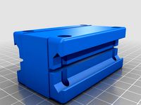
This is the electric version of my LGB remix of Raby's Knuckle Coupling.
It uses a slightly modified version of the knuckle and tang, which have a small detent added to make the knuckle actively open when the servo drives back a wire armature.
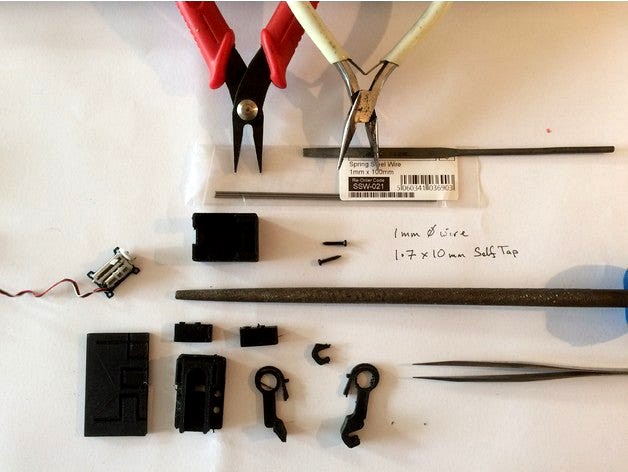
The Armature is the most difficult part to make and is quite critical to the operation. I made mine of 1mm spring steel wire, which was difficult to bend precisely. I designed a small jig to make bending easier, and photos of how it was intended to be used are included.
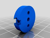
Once bent, the key thing is to fit it, and check that it moves smoothly. It shoud be fitted to the "lowest" of the three holes on the servo arm, and the top of the servo arm will need to be cut off so it has enough room to move.
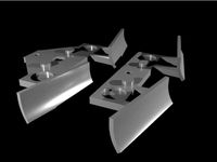
All parts will need some filing for smooth operation. The Motor Clap parts need to be glued (use acetone) to the Main Body. There is also a small knuckle part that needs to be glued to the bottom of the knuckle.
Assemble the tang first into the main housing, and then slide in the knuckle.
The assembly can then be fitted to the loco. The front coupling on the LGB Stainz has a deeper "front plate", and if you do not want to modify your model, you will have to use the "Stainz Front" variants of the motor clamp, Bottom housing and Main housing". This version has an extra cut out that allows it to fit, but you will have to do some filing to make sure the Tang and Knuckle can move freely.
Once you have the Armature nice and square (note: this is difficult) then fit it to the servo.
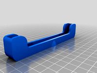
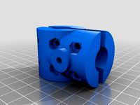
The servo then slides into the bottom housing, and the "front tabs" on the servo pcb should just be retained under some notches in the housing. The "back" of the servo, where the wires are, will sit down into a small recess. Bend the servo wires under the housing, and put some sticky tape on the. This will (should!) allow you to hold the box without the servo falling out.
Fit the main housing to the Loco, making sure that the knuckle and tang can move freely.
Then fit the "bottom housing", making sure that the Armature slides cleanly through the slots and is correctly engaged with the springs on the Tang and Knuckle. It is helpful at this stage if the servo is connected to a servo tester so you can check for free movement and operation.
Finally fit the two 1.7mm by 10mm screws and you should be finished.
https://youtu.be/sStIJU6A8bE
This has significant advantage that the servo is not actively holding the knuckle closed.
I have also updated the main knuckle coupling geometry so that the 'other' couplings are now all single piece. Unfortunately the revised geometry of the coupling means that it is not fully compatible with this original hook design.
Edit 30 May 2017 .. Getting a bit fustrated with this design.. Since changing to push capable knuckles, I have realised that the servo is underpowered. It is not strong enough to actually open the couplings and release.. I am still working on the concept, but please do not think this design is 'proven' ..
EDIT 28 Feb 2017: Modified the knuckle to be "push capable", in line with my revised push capable knuckle coupler. http://www.thingiverse.com/thing:1989545
Use the new "Push capable" knuckle and tang STL's in place of the old ones.
This is the electric version of my LGB remix of Raby's Knuckle Coupling.
It uses a slightly modified version of the knuckle and tang, which have a small detent added to make the knuckle actively open when the servo drives back a wire armature.
The Armature is the most difficult part to make and is quite critical to the operation. I made mine of 1mm spring steel wire, which was difficult to bend precisely. I designed a small jig to make bending easier, and photos of how it was intended to be used are included.
Once bent, the key thing is to fit it, and check that it moves smoothly. It shoud be fitted to the "lowest" of the three holes on the servo arm, and the top of the servo arm will need to be cut off so it has enough room to move.
All parts will need some filing for smooth operation. The Motor Clap parts need to be glued (use acetone) to the Main Body. There is also a small knuckle part that needs to be glued to the bottom of the knuckle.
Assemble the tang first into the main housing, and then slide in the knuckle.
The assembly can then be fitted to the loco. The front coupling on the LGB Stainz has a deeper "front plate", and if you do not want to modify your model, you will have to use the "Stainz Front" variants of the motor clamp, Bottom housing and Main housing". This version has an extra cut out that allows it to fit, but you will have to do some filing to make sure the Tang and Knuckle can move freely.
Once you have the Armature nice and square (note: this is difficult) then fit it to the servo.
The servo then slides into the bottom housing, and the "front tabs" on the servo pcb should just be retained under some notches in the housing. The "back" of the servo, where the wires are, will sit down into a small recess. Bend the servo wires under the housing, and put some sticky tape on the. This will (should!) allow you to hold the box without the servo falling out.
Fit the main housing to the Loco, making sure that the knuckle and tang can move freely.
Then fit the "bottom housing", making sure that the Armature slides cleanly through the slots and is correctly engaged with the springs on the Tang and Knuckle. It is helpful at this stage if the servo is connected to a servo tester so you can check for free movement and operation.
Finally fit the two 1.7mm by 10mm screws and you should be finished.
https://youtu.be/sStIJU6A8bE
Similar models
grabcad
free

LGB Knuckle Couplings
...k with different lgb bodies to avoid having to cut the coach/wagon /loco bodywork. i use the middle one for my 3d printed wagons.
thingiverse
free

Knuckle Coupler for LGB by dagnall53
...push them down firmly in the housings. it has similar "push" performance to the two part version and they...
grabcad
free

Servo operated Knuckle Coupling
...quire less filing, and the main coupling has been moved 1.2mm laterally to make for better alignment when coupling on the track.
thingiverse
free

Servo Operated Knuckle Coupling by dagnall53
...b housings. these are here: https://www.thingiverse.com/thing:1989545
chose the housing that works best for your truck/coach etc.
thingiverse
free

Revised G Scale LGB Servo Coupling by dagnall53
...ted to the loco. the photos on my older design (https://www.thingiverse.com/thing:398423) show the assembly process quite nicely.
grabcad
free

Revised Hook and Loop decoupler for LGB
...ve moved to my knuckle coupling .
i provide this file for anyone who can improve the design!. please let me know if you succeed!
thingiverse
free

Hudson Tipper railway truck. (new hubs) by dagnall53
...ginal versions.
may 2015 i have added stefan's hubs to the files.(see http://www.thingiverse.com/make:125279) thanks stefan!.
thingiverse
free
LGB Stainz spare parts by illust
...are parts for the lgb stainz locomotive. the handle next to the door comes with a special version with support for a sla printer.
thingiverse
free

Axial SCX10 Front Servo Bumper (Shortened Remix)
...rward to make room for my front mounted motor.
i have not printed this yet but will update when i do to confirm fit and function.
thingiverse
free

SG90 Servo Case by renzema
...m for drilling.
there are channels in the case and bottom for the servo wire.
fit for the servo into the base is by friction only
Dagnall53
thingiverse
free
5SCased tripod mount by dagnall53
...53
thingiverse
just a remix, slightly larger housing to take a cased 5s
included the 123d file so its easier to remix next time!
thingiverse
free

Walker Type Nautical Log by dagnall53
...lacement. designed to give approximately 20,000 pulses per nautical mile.
must be calibrated by user before any navigational use!
thingiverse
free
Catalac 8m Catamaran Cruiser Boat by dagnall53
...rawn originally in softfx, but the stl is unfortunately not printable as it is.
feel free to adapt to improve and make printable.
thingiverse
free

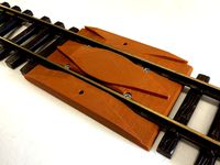
Points Servo Drive (Train track) by dagnall53
... spring mechanism allows the trains to push past "closed" points without derailing.
video: http://youtu.be/xdbzoc0kwsc
thingiverse
free

Man with CAP 1:32 scale by dagnall53
...n guard for a 1:32 scale railway.
supports to help print were made in meshmixer, so it should print "without supports".
thingiverse
free
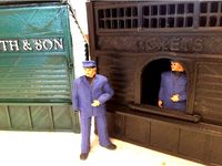
Ticket Office and WHS Kiosk by dagnall53
...ches) and two servo drives to drive points at the station. the code is available here https://github.com/dagnall53/espwifirocnet
thingiverse
free

Dimension test for coach side part of couplings by dagnall53
...://www.thingiverse.com/thing:1000218
but has not been built or tested and would need some tidying up to work as a coach coupling.
thingiverse
free
G scale Re-Railer by dagnall53
... the re-railer bottom surface.
i have attached the 123d file so you can modify the design if your railway does not use lgb locos.
thingiverse
free

Magnetic electrical connector for LGB Carriages and Trains by dagnall53
...ave used this to couple power from the engine to light the carriages without having to have track brushes on the carriage wheels.
thingiverse
free

G scale arch by dagnall53
...id not get all the "bricks" perfectly, but it looks good when painted with sandstone type paints. feel free to modify!
Knuckle
3d_export
$20

Knuckles
...knuckles
3dexport
knuckles
3ddd
$1

Сlassic Knuckles
...s
3ddd
sonic , knuckles , sega
сlassic knuckles
3d_export
$5

iron knuckle
...iron knuckle
3dexport
a classic iron knuckle.
3d_export
$5
knuckle joint
...knuckle joint
3dexport
this is a 3d model of knuckle joint
3d_export
$5

Knuckle Joint
...knuckle joint
3dexport
industry use knuckle joint
turbosquid
$19

Knuckle
... available on turbo squid, the world's leading provider of digital 3d models for visualization, films, television, and games.
3d_ocean
$2

Knuckle dusters
...pplied. it comes in obj/blend/dae/fbx formats, all of which are ready to import and render. check out my other cool stuff. enjoy!
turbosquid
$10

Knuckle-Knife
...id
royalty free 3d model knuckle-knife for download as blend on turbosquid: 3d models for games, architecture, videos. (1177912)
turbosquid
$1

Brass Knuckles
...uid
royalty free 3d model brass knuckles for download as fbx on turbosquid: 3d models for games, architecture, videos. (1484405)
turbosquid
$1

brass knuckles
...ty free 3d model brass knuckles for download as stl and sldpr on turbosquid: 3d models for games, architecture, videos. (1474385)
Coupler
turbosquid
$5

Jet ski coupler
...ee 3d model jet ski coupler for download as 3ds, 3dm, and stl on turbosquid: 3d models for games, architecture, videos. (1190218)
3d_export
$25
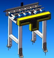
Scaffold 3D Model
...scaffolding modular aluminium ladder work platform building painting tube coupler construction max game low poly detailed uv scaffold 3d...
cg_studio
$29

Scaffold3d model
...scaffolding modular aluminium ladder work platform building painting tube coupler construction max game low poly detailed uv .obj .max...
3d_ocean
$25

PC Case
...3d audio blu-ray button card case cd computer conector coupler detailed dvd dvi electronics fan hd hdmi internet microphone...
3d_export
$199

AS15 - Mini Skid Steer - Loader Bucket
...arm<br>loader bucket<br>main body - a<br>main body - b<br>plastic parts<br>quick couplerlt;br>rear tire - left<br>rear tire - right<br>rear wheel - left<br>rear...
thingiverse
free
coupler by Curiositie
...coupler by curiositie
thingiverse
picatinny coupler
thingiverse
free

coupler by ratpog
...coupler by ratpog
thingiverse
coupler-comment for dimensions
thingiverse
free
Coupler by alexander111
...coupler by alexander111
thingiverse
two sided heavy duty coupler
thingiverse
free
Coupler by RoboticArts
...coupler by roboticarts
thingiverse
coupler of the robot made by robotic arts.
3dfindit
free
Coupler
...coupler
3dfind.it
catalog: abb installation products
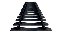
Railway
archibase_planet
free
Railway
...tact wire railroad contact wire railway line
railway contact wire n210814 - 3d model (*.gsm+*.3ds) for exterior 3d visualization.
3d_export
$9

railway stations
...railway stations
3dexport
railway stations<br>сollection of four railway stations.
turbosquid
$10
Railway
...yalty free 3d model railway for download as max, obj, and fbx on turbosquid: 3d models for games, architecture, videos. (1283992)
turbosquid
$29

railway
... available on turbo squid, the world's leading provider of digital 3d models for visualization, films, television, and games.
3d_export
$5

railway tank
...railway tank
3dexport
low-poly railway tank model
3d_export
$65

railway
...railway
3dexport
simple rendering of the scene file
3d_export
$65

railway
...railway
3dexport
simple rendering of the scene file
3d_export
$65

railway
...railway
3dexport
simple rendering of the scene file
3d_export
$65

railway
...railway
3dexport
simple rendering of the scene file
3d_export
$65

railway
...railway
3dexport
simple rendering of the scene file
G
3ddd
free

G. Moscatelli
...алка
вешалка 25 / 26 / 27коллекция: belle heleneбренд: g. moscatelliстрана: италияразмеры: высота - 190 / 195; диаметр - 50 / 60.
3ddd
$1

G Plan Vintage
...g plan vintage
3ddd
винтаж , g plan
g plan vintage armchair
turbosquid
free

G protein
...otein
turbosquid
free 3d model g protein for download as c4d on turbosquid: 3d models for games, architecture, videos. (1309660)
turbosquid
$14

Fence G
...turbosquid
royalty free 3d model fence g for download as fbx on turbosquid: 3d models for games, architecture, videos. (1310122)
turbosquid
$7

G for Gun
...rbosquid
royalty free 3d model g for gun for download as max on turbosquid: 3d models for games, architecture, videos. (1685215)
turbosquid
$5

G Ring
...
turbosquid
royalty free 3d model g ring for download as stl on turbosquid: 3d models for games, architecture, videos. (1285079)
turbosquid
$5

Letter G
...urbosquid
royalty free 3d model letter g for download as max on turbosquid: 3d models for games, architecture, videos. (1408463)
turbosquid
$5

Letter g
...urbosquid
royalty free 3d model letter g for download as max on turbosquid: 3d models for games, architecture, videos. (1408408)
3ddd
$1

Infiniti / G-Chair
...infiniti / g-chair
3ddd
infiniti
www.infinitidesign.it/ita/g-chair.php
3ddd
$1
кресло G-68
...кресло g-68
3ddd
кресло
кресло руководителя g-68
Electric
3d_export
$5

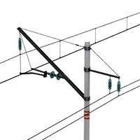
Electric pole
...electric pole
3dexport
electric pole for street, electricity line
3ddd
$1
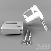
electric mixer
...electric mixer
3ddd
electric mixer , миксер
electric mixer
3ddd
$1

electrical installation
...electrical installation
3ddd
electrical installation , розетка
electrical installation
turbosquid
$19
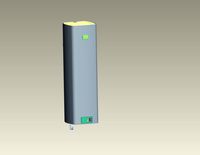
The electric water heater electric
... available on turbo squid, the world's leading provider of digital 3d models for visualization, films, television, and games.
turbosquid
free
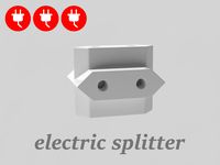
Electrical Outlet electric splitter
... available on turbo squid, the world's leading provider of digital 3d models for visualization, films, television, and games.
3d_ocean
$20
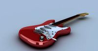
Electric Guitar
...electric guitar
3docean
electric electric guitar guitar music music instrument
model of a electric guitar created in maya.
3d_ocean
$12

Electric Shaver
...electric shaver
3docean
electric electric shaver hair removal personal care shaver shaving
electric shaver created in 3ds max.
3ddd
$1
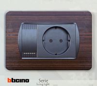
electrical switch
...h
3ddd
electrical , розетка
electrical switch from bticino company
series livinglight
3d_export
$7
Electric Conveyor
...electric conveyor
3dexport
electric conveyor
3d_export
$5
electric drums
...electric drums
3dexport
electric drums
Garden
3d_export
$18

garden-garden-tree 60
...garden-tree 60<br>executed in 3d max 2014<br>all textures and materials needed for the rendering found in the archive
3d_export
$18

garden-garden-tree 41
...garden-tree 41<br>executed in 3d max 2014<br>all textures and materials needed for the rendering found in the archive
3d_export
$18

garden-garden-tree 58
...garden-tree 58<br>executed in 3d max 2014<br>all textures and materials needed for the rendering found in the archive
3d_export
$18

garden-garden-tree 59
...garden-tree 59<br>executed in 3d max 2014<br>all textures and materials needed for the rendering found in the archive
3d_export
$18

garden-garden-tree 56
...garden-tree 56<br>executed in 3d max 2014<br>all textures and materials needed for the rendering found in the archive
3d_export
$18

garden-garden-tree 57
...garden-tree 57<br>executed in 3d max 2014<br>all textures and materials needed for the rendering found in the archive
turbosquid
$1

garden
...
turbosquid
royalty free 3d model garden for download as max on turbosquid: 3d models for games, architecture, videos. (1167978)
3d_export
$6

roof garden furniture seating and garden set
...roof garden furniture seating and garden set
3dexport
roof garden furniture seating and garden set
3d_export
$25

garden swing
...garden swing
3dexport
garden swing
3d_export
$12

Modern garden
...modern garden
3dexport
modern garden
Scale
turbosquid
$20
Weight scale or Bathroom Scale
...ght scale or bathroom scale for download as max, fbx, and obj on turbosquid: 3d models for games, architecture, videos. (1664576)
turbosquid
$19

Scale
...e
turbosquid
royalty free 3d model scale for download as fbx on turbosquid: 3d models for games, architecture, videos. (1411722)
turbosquid
$5
Scales
...s
turbosquid
royalty free 3d model scales for download as ma on turbosquid: 3d models for games, architecture, videos. (1393439)
turbosquid
$40

Scale
... available on turbo squid, the world's leading provider of digital 3d models for visualization, films, television, and games.
turbosquid
$17

Scales
... available on turbo squid, the world's leading provider of digital 3d models for visualization, films, television, and games.
turbosquid
$12

Scale
... available on turbo squid, the world's leading provider of digital 3d models for visualization, films, television, and games.
turbosquid
free

Scale
... available on turbo squid, the world's leading provider of digital 3d models for visualization, films, television, and games.
3d_export
$7

of scales
...s have a flat point of support. the samples are rendered in the standard cinema 4d renderer. enjoy your use and creative success.
3d_export
$5
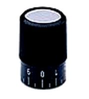
scale knob
...scale knob
3dexport
scale knob
3d_export
$20
cartoon weight scale or bathroom scale
...cartoon weight scale or bathroom scale
3dexport
texture size:512px number of texture:1 texture format: png