Thingiverse
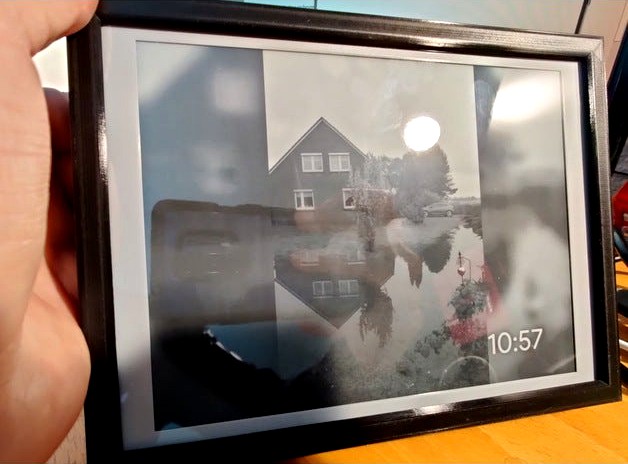
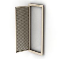
e-ink digital photo frame by t5b6_de
by Thingiverse
Last crawled date: 3 years, 3 months ago
This thing is uploaded due to a user request.
So I do not have measured the screws or the dc jack because i dont wanna put that thing apart again.
This thingie has no stand or buttons. Maybe i'll add a stand or buttons to the hex vent holes on the back. If your're using a smaller raspberry pi then pi 3 or 4, you can remove the holes on the back plate. otherwise raspberry pi 3 and 4 got very hot.
All screws and nuts are M3.
What you'll need:
130x180mm sheet of glass (has to be really accurate in size, not bigger, but can be slightly smaller (about half mm))
Raspberry Pi B+, Pi 2 B and up or Raspberry pi zero (w) with headers
7.8 in Waveshare eInk-panel with raspberry pi hat
a sort of dc-jack, i had one in my electronics trashcan, maybe you have to change your version of that outer frame and backplate.
(optional) a 3 amps step down converter pcb (5 Volts), i've added two mounting holes on that component frame for that. Otherwise use a 5 V power supply, but if voltage drops over the line, can cause serious problems with that hat.
6 screws for the backplate
6 nuts for frame
4 screws and nuts for the controller hat
4 screws and nuts for raspberry, if using zero, only two screws and nuts, or nothing if put directly on that hat (only zero (w))
2 or one screw and nuts for voltage regulator (depends on your design)
2 screws and nuts for the connector pfc connector pcb
for each (except for frame and connector pcb) screw a washer/spacer with 4.5mm height
(optional but recommend) plastic washer between every screw and pcb (except frame)
Steps to build, i highly recommend read this complete before build.
Print your parts in your color and material.
I recommend 0.25mm nozzle width (or smaller) and 0.1mm layer height. take care of the inserts for the nuts in the frame. plan the support for easy remove, you may have to tweak. I didn't plan to publish this thingie.
cleanup parts
insert nuts into the component frame for your needed parts. If printed correctly nuts should go in well but tight, so no glue needed.
shorten the screws if necessary, the screws MUST NOT touch the eInk-panel!
if using regular sized raspberry, you have to drill the mounting holes bigger to 3mm.
mount the PCBs:
insert ffc/fpc cable to hat
controller Hat, the exposed pin header goes into that slot on the right side.
ffc/fpc connector pcb, without a washer, directly on component frame
connect the other end to the input connector on the fpc-connector PCB
mount raspberry pi, or put pi zero directly on that hat, make sure to fold your ffc cable underneath your raspberry, that looks ok to you, but be very careful!
mount your voltage regulator (if using one) and connect wires.
if using "big" raspberry, connect the SPI cable shipped with the HAT to the raspberry and the hat controller. You'll have do drill the holes to 3mm otherwise M3 screws won't fit (raspi uses very unusual screw sizes)
insert sheet of glass, align to small side, otherwise there will be a gap,
insert the separator sheet, which separates display from glass, there is a bump on one side, this goes into the gap and prevents the glass sheet from moving around.
now, CAREFUL! insert panel, carefully bend the fpc around, so that connector is on back side (see photos), i do NOT recommend to stick that fpc cabling on the back side of that panel.
align that panel in the mid of the frame if possible.
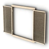
insert carefully that component-frame into that outer frame, DO NOT push it onto that panel, the fpc cable goes through the bigger squared hole left, stop right before the mid frame touches the panel. maybe go only a TINY bit further
align that panel so that this snaps to that components frame indent, use your small finger throgh the hexagonal holes.
if that panel is correctly aligned push VERY CAREFUL down that component frame.
The panel now should be movable, but only a tiny little bit.
insert the nuts of the outer frame into the inner holes.
connect your dc-jack to that voltage regulator PCB if you've one.
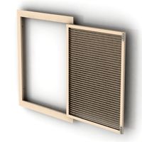
align and place the backplate into that frame.
screw the 6 outer screws to the frame on the back.
assembly is done.
So I do not have measured the screws or the dc jack because i dont wanna put that thing apart again.
This thingie has no stand or buttons. Maybe i'll add a stand or buttons to the hex vent holes on the back. If your're using a smaller raspberry pi then pi 3 or 4, you can remove the holes on the back plate. otherwise raspberry pi 3 and 4 got very hot.
All screws and nuts are M3.
What you'll need:
130x180mm sheet of glass (has to be really accurate in size, not bigger, but can be slightly smaller (about half mm))
Raspberry Pi B+, Pi 2 B and up or Raspberry pi zero (w) with headers
7.8 in Waveshare eInk-panel with raspberry pi hat
a sort of dc-jack, i had one in my electronics trashcan, maybe you have to change your version of that outer frame and backplate.
(optional) a 3 amps step down converter pcb (5 Volts), i've added two mounting holes on that component frame for that. Otherwise use a 5 V power supply, but if voltage drops over the line, can cause serious problems with that hat.
6 screws for the backplate
6 nuts for frame
4 screws and nuts for the controller hat
4 screws and nuts for raspberry, if using zero, only two screws and nuts, or nothing if put directly on that hat (only zero (w))
2 or one screw and nuts for voltage regulator (depends on your design)
2 screws and nuts for the connector pfc connector pcb
for each (except for frame and connector pcb) screw a washer/spacer with 4.5mm height
(optional but recommend) plastic washer between every screw and pcb (except frame)
Steps to build, i highly recommend read this complete before build.
Print your parts in your color and material.
I recommend 0.25mm nozzle width (or smaller) and 0.1mm layer height. take care of the inserts for the nuts in the frame. plan the support for easy remove, you may have to tweak. I didn't plan to publish this thingie.
cleanup parts
insert nuts into the component frame for your needed parts. If printed correctly nuts should go in well but tight, so no glue needed.
shorten the screws if necessary, the screws MUST NOT touch the eInk-panel!
if using regular sized raspberry, you have to drill the mounting holes bigger to 3mm.
mount the PCBs:
insert ffc/fpc cable to hat
controller Hat, the exposed pin header goes into that slot on the right side.
ffc/fpc connector pcb, without a washer, directly on component frame
connect the other end to the input connector on the fpc-connector PCB
mount raspberry pi, or put pi zero directly on that hat, make sure to fold your ffc cable underneath your raspberry, that looks ok to you, but be very careful!
mount your voltage regulator (if using one) and connect wires.
if using "big" raspberry, connect the SPI cable shipped with the HAT to the raspberry and the hat controller. You'll have do drill the holes to 3mm otherwise M3 screws won't fit (raspi uses very unusual screw sizes)
insert sheet of glass, align to small side, otherwise there will be a gap,
insert the separator sheet, which separates display from glass, there is a bump on one side, this goes into the gap and prevents the glass sheet from moving around.
now, CAREFUL! insert panel, carefully bend the fpc around, so that connector is on back side (see photos), i do NOT recommend to stick that fpc cabling on the back side of that panel.
align that panel in the mid of the frame if possible.
insert carefully that component-frame into that outer frame, DO NOT push it onto that panel, the fpc cable goes through the bigger squared hole left, stop right before the mid frame touches the panel. maybe go only a TINY bit further
align that panel so that this snaps to that components frame indent, use your small finger throgh the hexagonal holes.
if that panel is correctly aligned push VERY CAREFUL down that component frame.
The panel now should be movable, but only a tiny little bit.
insert the nuts of the outer frame into the inner holes.
connect your dc-jack to that voltage regulator PCB if you've one.
align and place the backplate into that frame.
screw the 6 outer screws to the frame on the back.
assembly is done.
Similar models
thingiverse
free

FFC to FFC adapter extension clamp for Geeetech A10 by Deejayshag
... effectively for other ffc cables as well, as long as they have less than 40 pins (think raspberry pi camera, which has 15 pins).
thingiverse
free

Anet A8 display-backplate Raspberry Pi Zero mount by whyismynameallwaystaken
... slim cases, but i can't remember which one i printed. it has additional holes for cable straps and push-in slots for cables.
thingiverse
free

Raspberry Pi A+ Stand by raspberryjamberlin
...too because stiff cables tended to make the whole stand lift off the table. this time i hope the placement allows for cable bend.
thingiverse
free

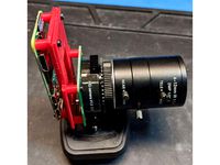
Raspberry Pi Zero W camera mount by thirdhorizon
...is is used on the top frame of a barexy printer, and is powered directly from the paneldue 5v connector on the duet 2 wifi board.
thingiverse
free

Raspberry Pi Zero W Camera Night Vision Camera ( Remix ) by krexas
...fectly with a raspberry pi zero w and a night vision camera
raspberry pi zero w
night vision camera
2 x ir lights
ffc cable 15 cm
thingiverse
free

Pi Zero 2020 mount by PyroNyzen
...giverse
i wanted to mount a pi zero to my p902 frame so i combined the screw holes for the raspberry pi 2 b 2020 case with this.
thingiverse
free

Frame for Raspberry Pi by builtbybogus
...ottom. you can do that, too.
attention: this case works only with the raspberry pi b (the one with holes in the pcb). have fun!
thingiverse
free

Raspberry Pi Zero Backplate by Crushersun
...raspberry pi zero backplate by crushersun
thingiverse
just my version of a backplate for the pi zero.
thingiverse
free

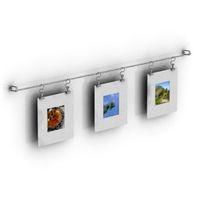
raspberry panel mount rails by hjkoskel
... inserts i used some cheap ebay metal inserts.
"m3x6mm threaded round metal knurl thread insert nuts brass tone 100pcs"
thingiverse
free
raspberry pi zero hq camera bracket by openloopengineer
...i with the same size screws.
i used the short raspberry pi zero camera cable that comes with the official raspberry pi zero case.
Ink
turbosquid
$3

Ink
... available on turbo squid, the world's leading provider of digital 3d models for visualization, films, television, and games.
turbosquid
$12

Ink Slab brush double bat ink slab
...model ink slab brush double bat ink slab for download as max on turbosquid: 3d models for games, architecture, videos. (1614863)
turbosquid
$5

Ink Bottle
...
royalty free 3d model ink bottle for download as fbx and obj on turbosquid: 3d models for games, architecture, videos. (1686322)
turbosquid
$10

Ink Pen
... available on turbo squid, the world's leading provider of digital 3d models for visualization, films, television, and games.
turbosquid
$3

Ink Bottle
... available on turbo squid, the world's leading provider of digital 3d models for visualization, films, television, and games.
turbosquid
$2

ink cartdriges
... available on turbo squid, the world's leading provider of digital 3d models for visualization, films, television, and games.
turbosquid
free
Ink pen
... available on turbo squid, the world's leading provider of digital 3d models for visualization, films, television, and games.
3d_export
$65

ink pavilion
...ink pavilion
3dexport
simple rendering of the scene file
3d_export
$30

ink animation
...ink animation
3dexport
simple rendering of the scene file
3d_export
$30

ink painting
...ink painting
3dexport
simple rendering of the scene file
Photo
3ddd
$1

photo frame
...photo frame
3ddd
photo frame
3ddd
$1

Photo Frame
...photo frame
3ddd
рисунок
photo frame
3d_export
$5

photo frame
...or photos, pictures. you can put shes anywhere. in the kitchen, on the table in the bedroom, on the shelf in the hall, and so on.
archive3d
free
Photos 3D Model
...tos photo photos set
set photos n160216 - 3d model (*.gsm+*.3ds) for interior 3d visualization.
3d_export
$5
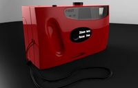
Photo 3D Model
...photo 3d model
3dexport
photo
photo 3d model max140588 62242 3dexport
3d_export
$14

photo printer
...g projects, and was originally modeled in 3ds max 2012 and rendered with v-ray. renders have no postprocessing. hope you like it!
turbosquid
$10

photo frame
...osquid
royalty free 3d model photo frame for download as obj on turbosquid: 3d models for games, architecture, videos. (1404417)
turbosquid
$9

Photo studio
...uid
royalty free 3d model photo studio for download as blend on turbosquid: 3d models for games, architecture, videos. (1498830)
turbosquid
$5

Photo Frame
...royalty free 3d model photo frame for download as fbx and upk on turbosquid: 3d models for games, architecture, videos. (1163533)
turbosquid
$2

Photo Frame
...royalty free 3d model photo frame for download as max and fbx on turbosquid: 3d models for games, architecture, videos. (1352878)
Frame
archibase_planet
free
Frame
...frame
archibase planet
frame photo frame
frame n190813 - 3d model (*.gsm+*.3ds) for interior 3d visualization.
archibase_planet
free
Frame
...frame
archibase planet
frame photo frame
frame n071113 - 3d model (*.gsm+*.3ds) for interior 3d visualization.
3ddd
$1

Frame
...frame
3ddd
frame
3ddd
free
Frame
...frame
3ddd
frame
archibase_planet
free

Frame
...frame
archibase planet
frame mirror frame ornament
frame n260113 - 3d model (*.gsm+*.3ds) for interior 3d visualization.
archibase_planet
free

Frame
...frame
archibase planet
frame photo frame
frame photo n190813 - 3d model (*.gsm+*.3ds) for interior 3d visualization.
archibase_planet
free
Frame
...frame
archibase planet
frame window window frame
frame 1 - 3d model (*.gsm+*.3ds) for interior 3d visualization.
archibase_planet
free
Frame
...frame
archibase planet
frame window frame window
frame 3 - 3d model (*.gsm+*.3ds) for interior 3d visualization.
archibase_planet
free
Frame
...frame
archibase planet
frame wall frame decoration
frame 1 - 3d model (*.gsm+*.3ds) for interior 3d visualization.
archibase_planet
free
Frame
...frame
archibase planet
frame window window frame
frame 2 - 3d model (*.gsm+*.3ds) for interior 3d visualization.
Digital
turbosquid
$20
Digits
...available on turbo squid, the world's leading provider of digital 3d models for visualization, films, television, and...
turbosquid
$79

Digital piano
... available on turbo squid, the world's leading provider of digital 3d models for visualization, films, television, and games.
turbosquid
$70

Digital Cameras
... available on turbo squid, the world's leading provider of digital 3d models for visualization, films, television, and games.
turbosquid
$50

Digital Indicator
... available on turbo squid, the world's leading provider of digital 3d models for visualization, films, television, and games.
turbosquid
$49

Digital Clock
... available on turbo squid, the world's leading provider of digital 3d models for visualization, films, television, and games.
turbosquid
$49
Digital Printer
... available on turbo squid, the world's leading provider of digital 3d models for visualization, films, television, and games.
turbosquid
$39

Digital scales
... available on turbo squid, the world's leading provider of digital 3d models for visualization, films, television, and games.
turbosquid
$25
Digital 21
... available on turbo squid, the world's leading provider of digital 3d models for visualization, films, television, and games.
turbosquid
$25
Digital Durometer
... available on turbo squid, the world's leading provider of digital 3d models for visualization, films, television, and games.
turbosquid
$25

Digital Scales
... available on turbo squid, the world's leading provider of digital 3d models for visualization, films, television, and games.
E
3ddd
$1
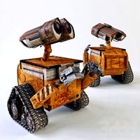
WALL-E
...wall-e
3ddd
wall-e , робот
wall-e
3d_export
$100

e-rickshaw
...e-rickshaw
3dexport
e-rickshaw- it have 3d model of passenger e-rickshaw
3d_ocean
$12
Wall E
...wall e
3docean
character robot wall e
its a 3d model of wall e….
turbosquid
$68
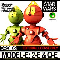
Model-E Droids 2-E Q-E Star Wars
... available on turbo squid, the world's leading provider of digital 3d models for visualization, films, television, and games.
cg_studio
$45
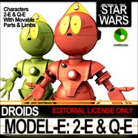
Model-E Droids 2-E Q-E Star Wars3d model
....3ds .c4d .obj .vue - model-e droids 2-e q-e star wars 3d model, royalty free license available, instant download after purchase.
3d_export
$100
e-rickshaw
...e-rickshaw
3dexport
e-rickshaw design for passenger it have all mechanical component
design_connected
$7
Cone E
...cone e
designconnected
bonaldo cone e computer generated 3d model. designed by pasini, ennio.
3ddd
$1

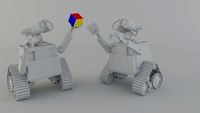
Wall-E NEW
...wall-e new
3ddd
wall-e , робот
wall-e
design_connected
$29

Extrasoft E
...extrasoft e
designconnected
living divani extrasoft e computer generated 3d model. designed by lissoni, piero.
3ddd
$1

E-Turn
... скамейка
современная скамейка фирмы kundalini.
модель e-turn.
дизайнер brodie neil.
размеры: h 42 cm l 185 cm w 54 cm