Thingiverse
Dual Pogo Pins Probe Clip for Dual Castellated Modules by mofosyne
by Thingiverse
Last crawled date: 3 years ago
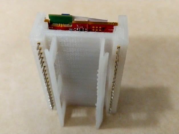
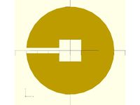
This is a pogo pin adaptor for boards that uses dual castellation for surface mounted modules.
It takes advantage and requires the use of cutouts under the modules as an alignment for the pogo pin positioning and the 3d printed retention clips.
I have not bothered to make this parametric. But can do if requested. This was created to solve a specific problem I had.
You may be interested in that I took around 10 revisions before getting the final 11th revision that I liked best.
Once printed, you need to insert the pogo pins in, then insert the modules on top and solder the modules to the pogo pins legs.
Do note you will need to do a test print first, because this design requires tight tolerance and thus this may differ between printers. But once dialed in, the print is repeatable.
Revision Notes
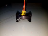
Rev2 : Second revision since I had to deal with a module that requires a different dimention in the cutout. And also this module I had to deal with also has additional contact points on the top of the board.
Rev1 : First real release. Clips well and is designed for a module with only two castellations.
Print Notes
This is specifically designed not to require infills, and was printed on a 0.8mm nozzle at 0.2mm layer height. Took 54 minutes to print.
Also this requires accurate z axis calibration. You can use https://www.thingiverse.com/thing:3113686 to check.
Default Design Spec
Since I have not made this parametric, unless you are willing to manually adjust the openscad design files... these are the specs I have done this in.
Spec of the probe pins
Probe extention/spring length: 3mm
Body of the probe : 13mm
probe pin diameter : 1mm
Spec of the castellation module (rev1)
module x length : 49.4mm
module y length : 27.5mm
module y length cutout area : 49.4mm
module y length cutout area : 18.83mm
pin pair count : 18
spacing between each pair of probes : 2.54mm
first probe spacing from bottom of module : 4mm
Spec of the castellation module (rev2)
module x length : 49.4mm
module y length : 27.5mm
module y length cutout area : 48.3mm
module y length cutout area : 18.9mm
pin pair count : 18
spacing between each pair of probes : 2.54mm
first probe spacing from bottom of module : 3mm
Design Notes:
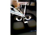
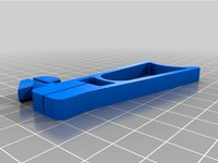
Tried different clip design. The best is often the simplest. I tried other designs to try and add bit of kerning to reduce the springyness, but found that I could easily just reduce the springyness to a manageable level by cutting holes on the clip. Thus the more reliable and straightforward clip design similar to revision 1 was chosen.
Needed to position the pcb with spacing away from the pogo pin. This is because with this many pogo pins, having it pushed even 50% of the way would have the pogo pins provide too much force on the pcb... straining the retaining clip. Thus just spacing the pcb surface 2/3 away from the pogo pin and reducing the retaining clip force, allowed for easier connection and disconnection.
I opted for the sharp tooth pogo pin, but this may not be a good idea for higher current devices. For high current requirements, you need to pick a pogo pin with a head that has multiple contact points.
It takes advantage and requires the use of cutouts under the modules as an alignment for the pogo pin positioning and the 3d printed retention clips.
I have not bothered to make this parametric. But can do if requested. This was created to solve a specific problem I had.
You may be interested in that I took around 10 revisions before getting the final 11th revision that I liked best.
Once printed, you need to insert the pogo pins in, then insert the modules on top and solder the modules to the pogo pins legs.
Do note you will need to do a test print first, because this design requires tight tolerance and thus this may differ between printers. But once dialed in, the print is repeatable.
Revision Notes
Rev2 : Second revision since I had to deal with a module that requires a different dimention in the cutout. And also this module I had to deal with also has additional contact points on the top of the board.
Rev1 : First real release. Clips well and is designed for a module with only two castellations.
Print Notes
This is specifically designed not to require infills, and was printed on a 0.8mm nozzle at 0.2mm layer height. Took 54 minutes to print.
Also this requires accurate z axis calibration. You can use https://www.thingiverse.com/thing:3113686 to check.
Default Design Spec
Since I have not made this parametric, unless you are willing to manually adjust the openscad design files... these are the specs I have done this in.
Spec of the probe pins
Probe extention/spring length: 3mm
Body of the probe : 13mm
probe pin diameter : 1mm
Spec of the castellation module (rev1)
module x length : 49.4mm
module y length : 27.5mm
module y length cutout area : 49.4mm
module y length cutout area : 18.83mm
pin pair count : 18
spacing between each pair of probes : 2.54mm
first probe spacing from bottom of module : 4mm
Spec of the castellation module (rev2)
module x length : 49.4mm
module y length : 27.5mm
module y length cutout area : 48.3mm
module y length cutout area : 18.9mm
pin pair count : 18
spacing between each pair of probes : 2.54mm
first probe spacing from bottom of module : 3mm
Design Notes:
Tried different clip design. The best is often the simplest. I tried other designs to try and add bit of kerning to reduce the springyness, but found that I could easily just reduce the springyness to a manageable level by cutting holes on the clip. Thus the more reliable and straightforward clip design similar to revision 1 was chosen.
Needed to position the pcb with spacing away from the pogo pin. This is because with this many pogo pins, having it pushed even 50% of the way would have the pogo pins provide too much force on the pcb... straining the retaining clip. Thus just spacing the pcb surface 2/3 away from the pogo pin and reducing the retaining clip force, allowed for easier connection and disconnection.
I opted for the sharp tooth pogo pin, but this may not be a good idea for higher current devices. For high current requirements, you need to pick a pogo pin with a head that has multiple contact points.
Similar models
thingiverse
free

TYWE3S Flashing Jig no alligator clips by SrGeek
...ia 0.68mm 75g pressure spring test probe pin
advantage you can keep all the wires, the jig and the ftdi adapter as a kit together
grabcad
free

simple z-probe with spring pogo
...e with spring pogo
grabcad
materials requires:
3 spring pogo p100-b
1 shaft motor connector 3.175mm-2mm
epoxy ab glue
pcb 2 side
thingiverse
free
PCB Workstation by kompara
...onal screws, mattress and washers
spring loaded test probes (pogo pin) link
2.54mm jumper cables link
more on this on my website.
grabcad
free

Pogo Pin, for 0.075" centers
...pogo pin, for 0.075" centers
grabcad
pogo pin, for 0.075" centers
cup style probe
crimp style receptacle
grabcad
free

Pogo Pin, for 0.100" centers
...pogo pin, for 0.100" centers
grabcad
pogo pin, for 0.075" centers
cup style probe
crimp style receptacle
thingiverse
free
Sonoff Basic R2 Pogo Pins Header
...r soldering.
the pogo pins used are the p75-e2
the springs are random ones salvaged probably from an old xerox printer (no specs)
thingiverse
free

ESP8266 Pogo Pin carriage and base by benvonhandorf
...ards i had lying around. these are quite small and the dovetail isn't the same size as any other breadboards i own, so ymmv.
thingiverse
free

ESP-12E pogo pin programmer
...pogo pins and mounting a serial module to allow programming of a bare esp-12e module. probably works for esp-12f too. and others?
grabcad
free

Castellated Stamp Test Pin
...model comes in two options:
unbent - the pin's natural state when not inserted into the pcb
bent - when soldered onto the pcb
grabcad
free

PCB mounted magnetic pogo pin connector
... mounted magnetic pogo pin connector
grabcad
2.5mm pitch 4-pin magnetic pogo pin connector commonly found on ebay and aliexpress
Mofosyne
thingiverse
free

Parametric screwdriver hook For Tslot Mounting (OpenSCAD) by mofosyne
...er hook for tslot mounting (openscad) by mofosyne
thingiverse
got a desk with tslot rails, would be nice to screwdriver on it...
thingiverse
free

Parametric Cable Loop For Tslot Mounting by mofosyne
...
parametric cable organiser for tslot mounting
by brian khuu (2020)
got a desk with tslot rails, would be nice to organise cable
thingiverse
free

Parametric Spacer For Male Pin Headers by mofosyne
... spacers for it, so made this.
current default values assumes you are using industry standard imperial header sizing and spacing.
thingiverse
free
Parametric Tslot Mounting of Paper Clip (OpenSCAD) by mofosyne
...to it
remixed from https://www.thingiverse.com/thing:3045980 "clip on paper holder" by ken_applications august 12, 2018
thingiverse
free

Cocoon create touch fan covers (Remix for 0.8mm nozzle) by mofosyne
...rill so that it can be sliced under thicker 0.8mm nozzle in cura.
the modification was done via meshmixer using the extrude tool.
thingiverse
free

BLTouch Z Height Calibration Gauge V1 by mofosyne
... bltouch region.
when the nozzle adjust stage comes up, measure against the corresponding layer squish height you are aiming for.
thingiverse
free

Plastic Base for programmable music box by mofosyne
...ole to hole x dimension: 50.15
hole to hole y dimension: 37.55
you can also use this as a base to build other more complex boxes.
thingiverse
free
Fast And Basic Clothing Hanger Divider (Uberized) by mofosyne
...ce think?
unlike the original design, this is not too practical. as the hole inside 20cm. unless you have a 20cm diameter hanger?
thingiverse
free

Fast And Basic Clothing Hanger Divider by mofosyne
...u need to have a white sticker to label it. if on a different colour, you can write labels on it instead with a black marker pen.
thingiverse
free

Adhesive Ceiling Loop Mount by mofosyne
...ated for "ceiling mounted stovetop firestop fire exingisher (single or pair)" https://www.thingiverse.com/thing:3035398
Pogo
turbosquid
$14

Tootool Pogo
...odel tootool pogo for download as 3ds, max, dxf, obj, and fbx on turbosquid: 3d models for games, architecture, videos. (1215989)
3ddd
$1

Joel Escalona / Pogo Table
...joel escalona / pogo table
3ddd
escalona
pogo table by joel escalona
turbosquid
free
pogo stick004.lwo
... available on turbo squid, the world's leading provider of digital 3d models for visualization, films, television, and games.
3d_export
$20
Pogo Stick 3D Model
...go toy jumping jump spring action child outdoor games pole stunt kids pogostick bounce
pogo stick 3d model firdz3d 77099 3dexport
3ddd
$1
Joel Escalona / Pogo Table
... стол
pogo table – это забавное изобретение дизайнера joel escalona, предназначенное для украшения интерьера детских комнат.
3d_export
$10
Pogo Stick v2 3D Model
...toy jumping jump spring action child outdoor games pole stunt kids pogostick bounce
pogo stick v2 3d model firdz3d 90759 3dexport
3d_export
$7

table andersen
...table andersen 3dexport writing desk andersen: dimensions: 1800x750x750 mm<br>laredoute pogo stool: dimensions: ø280 x 470 mm<br>table lamp evoluce satta:...
thingiverse
free

pogo jig essentials by HLCHLCHLC
...ust/scale the vias.
we'd love to know how you make your own pogo jigs. don't hesitate to leave us a comment when you did!
unity_asset_store
$9
Pogo Stick
...elevate your workflow with the pogo stick asset from studiolab. find this & other props options on the unity asset store.
thingiverse
free

Cobra Pogo by SnakeEyes397
... pogo gun
the model is scaled so that 100% matches the dimensions of the original toy. details are optimized for printing at 20%.
Castellated
turbosquid
$10

Castel
...
turbosquid
royalty free 3d model castel for download as fbx on turbosquid: 3d models for games, architecture, videos. (1677586)
turbosquid
$10

Castel
...turbosquid
royalty free 3d model castel for download as 3dmf on turbosquid: 3d models for games, architecture, videos. (1247460)
3ddd
free
Faber - Castell
...faber - castell
3ddd
faber-castell , карандаш
текстуры в архив. ест модель в fbx.
turbosquid
$3
castellated nut
...lty free 3d model castellated nut for download as c4d and obj on turbosquid: 3d models for games, architecture, videos. (1557872)
turbosquid
$1

NURBS Castel
... available on turbo squid, the world's leading provider of digital 3d models for visualization, films, television, and games.
turbosquid
free
medieval castel
... available on turbo squid, the world's leading provider of digital 3d models for visualization, films, television, and games.
turbosquid
$15

castel
...l
turbosquid
royalty free 3d model mosqe for download as dwg on turbosquid: 3d models for games, architecture, videos. (1580389)
3ddd
$1

набор карандашей Faber Castell
... , набор карандашей
подарочный набор faber-castell polychromos pencils (120 карандашей).
3d_export
$20
Old castel 3D Model
...old castel 3d model
3dexport
royal
old castel 3d model bsmeher 26516 3dexport
3d_export
$5
Faber Castell rapidograph 3D Model
... rapidograph 3d model
3dexport
pen pencil rapidograph faber castell
faber castell rapidograph 3d model 3dcraftsman 63700 3dexport
Probe
turbosquid
$25
Probe
... available on turbo squid, the world's leading provider of digital 3d models for visualization, films, television, and games.
turbosquid
$12
Mars probe space space exploration lunar probe
...be space space exploration lunar probe for download as max on turbosquid: 3d models for games, architecture, videos. (1630876)
turbosquid
$35
Space Probe
...osquid
royalty free 3d model space probe for download as c4d on turbosquid: 3d models for games, architecture, videos. (1571168)
turbosquid
$15
Space Probe
...osquid
royalty free 3d model space probe for download as obj on turbosquid: 3d models for games, architecture, videos. (1314864)
turbosquid
$25
Robot Probe
...y free 3d model robot probe for download as fbx, obj, and dae on turbosquid: 3d models for games, architecture, videos. (1537490)
turbosquid
$1

Dental Probe
...e 3d model dental probe for download as ma, obj, fbx, and stl on turbosquid: 3d models for games, architecture, videos. (1312400)
turbosquid
$60
Police Probe
... available on turbo squid, the world's leading provider of digital 3d models for visualization, films, television, and games.
turbosquid
$10
Dental Probe
... available on turbo squid, the world's leading provider of digital 3d models for visualization, films, television, and games.
turbosquid
$9

Space probe
... available on turbo squid, the world's leading provider of digital 3d models for visualization, films, television, and games.
turbosquid
free

Cassini Probe
... available on turbo squid, the world's leading provider of digital 3d models for visualization, films, television, and games.
Dual
turbosquid
free

Dual Pistols
...ls
turbosquid
free 3d model dual pistols for download as fbx on turbosquid: 3d models for games, architecture, videos. (1320360)
turbosquid
$2
Dual Axe
...urbosquid
royalty free 3d model dual axe for download as fbx on turbosquid: 3d models for games, architecture, videos. (1332372)
turbosquid
$10
Dual Lesaths
... available on turbo squid, the world's leading provider of digital 3d models for visualization, films, television, and games.
3ddd
$1
плитка Dual Bianco (Испания)
...й плитки venis dual (испания). технические качества: устойчивость к стирания, отличная геометрия, отсутствие проблем при укладке.
turbosquid
$35

Dual Mesh Fonts
...ree 3d model dual mesh fonts for download as ma, obj, and fbx on turbosquid: 3d models for games, architecture, videos. (1352989)
turbosquid
$29

Dual Flask with Bungs
...del dual flask with bungs for download as obj, fbx, and blend on turbosquid: 3d models for games, architecture, videos. (1210512)
turbosquid
$19
Dual Socket Plug
...3d model dual socket plug for download as obj, fbx, and blend on turbosquid: 3d models for games, architecture, videos. (1303912)
turbosquid
$13

Dual Adjustable Pulley
... available on turbo squid, the world's leading provider of digital 3d models for visualization, films, television, and games.
turbosquid
$10
Amoi N809 Dual
... available on turbo squid, the world's leading provider of digital 3d models for visualization, films, television, and games.
turbosquid
$5
Dual Turret Tank
... available on turbo squid, the world's leading provider of digital 3d models for visualization, films, television, and games.
Modules
turbosquid
$4

Module
...
turbosquid
royalty free 3d model module for download as max on turbosquid: 3d models for games, architecture, videos. (1259603)
3d_export
free

Martian module
...martian module
3dexport
martian module objects 18 textures are missing
design_connected
$39
Kennedee Moduls
...kennedee moduls
designconnected
kennedee moduls computer generated 3d model. designed by massaud, jean-marie.
design_connected
$39

Sayonara Moduls
...sayonara moduls
designconnected
bbb emmebonacina sayonara moduls computer generated 3d model. designed by decursu, giorgio.
design_connected
$27

Togo Moduls
...togo moduls
designconnected
ligne roset togo moduls computer generated 3d model. designed by ducaroy, michel.
design_connected
$34
Nuvola Moduls
...nuvola moduls
designconnected
bonaldo nuvola moduls 2-seater computer generated 3d model. designed by giuseppe viganò.
3d_export
free
Hibernation module
...hibernation module
3dexport
design_connected
$27

Sabi moduls
...sabi moduls
designconnected
paola lenti sabi moduls 2-seater computer generated 3d model. designed by francesco rota.
3d_export
$50

pls concrete module
...pls concrete module
3dexport
pls concrete module<br>pls with concrete mobile mixer module m5
turbosquid
free
Hibernation module
...squid
free 3d model hibernation module for download as blend on turbosquid: 3d models for games, architecture, videos. (1667696)
Pins
3d_export
$5

Pin
...pin
3dexport
very god pin
3d_ocean
$1

Bowling pins
...e inside of cinema 4d. there are 3 files included : pin.c4d : pins array.c4d : pin.obj pins array is the bowling pins set up i...
3d_ocean
$5

Pins
...v-ray studio render setting ready close-ups camera support polys: low: 6.314 high: 1.681.922 (with turbosmooth modifier) *incl...
turbosquid
$4

pin
...osquid
royalty free 3d model pin for download as 3dm and max on turbosquid: 3d models for games, architecture, videos. (1669685)
3d_ocean
$15

Map Pins
...map pins
3docean
factory kremlin map moscow oil oil-derrick pin pins red russia soviet soviet union star
some stylized map pins.
turbosquid
$9

Pins
...lty free 3d model pins for download as 3ds, max, obj, and fbx on turbosquid: 3d models for games, architecture, videos. (1506195)
turbosquid
$7
Pin
...alty free 3d model pin for download as dae, fbx, obj, and stl on turbosquid: 3d models for games, architecture, videos. (1609891)
turbosquid
$35

Pins
... available on turbo squid, the world's leading provider of digital 3d models for visualization, films, television, and games.
turbosquid
$20

Pin
... available on turbo squid, the world's leading provider of digital 3d models for visualization, films, television, and games.
turbosquid
$20

Pin
... available on turbo squid, the world's leading provider of digital 3d models for visualization, films, television, and games.
Clip
archibase_planet
free
Clip
...clip
archibase planet
paper-clip clip office equipment
clip band - 3d model for interior 3d visualization.
3d_export
$5
screw clip
...screw clip
3dexport
screw clip
3d_ocean
$4
Butterfly clip
... a butterfly clip, it comes with a ready to render set for out of the box rendering. obj version and max alones version included.
turbosquid
$2

clip
...
royalty free 3d model clip for download as ma, obj, and fbx on turbosquid: 3d models for games, architecture, videos. (1358622)
turbosquid
$5

Clip
...lty free 3d model clip for download as c4d, 3ds, fbx, and obj on turbosquid: 3d models for games, architecture, videos. (1521355)
turbosquid
$19
Clip
... available on turbo squid, the world's leading provider of digital 3d models for visualization, films, television, and games.
turbosquid
$4
Clips
... available on turbo squid, the world's leading provider of digital 3d models for visualization, films, television, and games.
turbosquid
$3
clip
... available on turbo squid, the world's leading provider of digital 3d models for visualization, films, television, and games.
turbosquid
$2

clips
... available on turbo squid, the world's leading provider of digital 3d models for visualization, films, television, and games.
turbosquid
free

Clip
... available on turbo squid, the world's leading provider of digital 3d models for visualization, films, television, and games.