Thingiverse
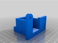
Dual CoreXY setup that uses LME12UU and 12mm shafts by Thump2010
by Thingiverse
Last crawled date: 3 years ago
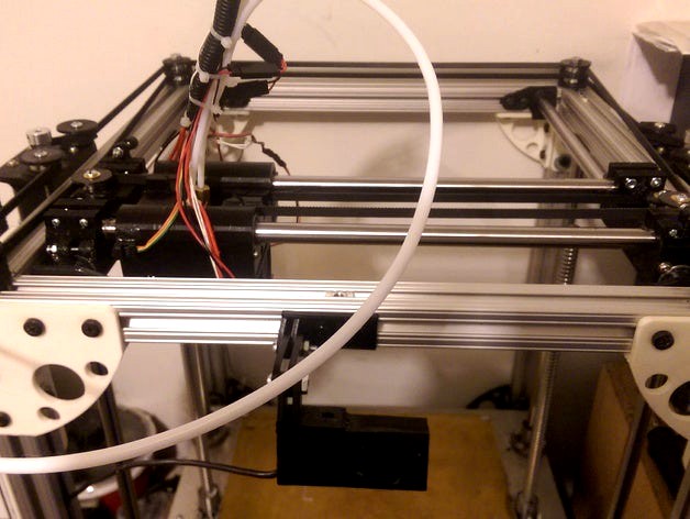
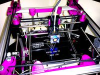
This is a modified CoreXY setup I have been working on, I have to do the corner bearing holder and the motor mount yet, this is for a printer I am creating, it uses LME12UU bearings and 12mm shafts, I went bigger as this is also used in a much larger printer also, that and I like tanks, I don't like things that are flimsy and flex.
It does not cross over it runs at two different levels so everything stays straight.
I used 686Z bearings on the ends and the flanges I made are designed to be paused then the bearing added then printing to continue so they are encased in plastic (a blast of a heat gun before hitting resume makes a strong bond for the continuing layer.)
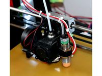
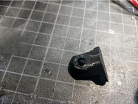
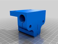
I made it around this hotend that I got from amazon:
Signswise Assembled J-head Hotend 0.4mm Nozzle Printer Head for 1.75mm Filamentshttp://www.amazon.com/Signswise-Assembled-J-head-Printer-Filaments/dp/B00SWLMWDM
It shouldn't take much to change the clamp to fit your hotend.
Things to do:
Motor mounts.
Corner bearing mounts.
Spot for a small magnet on the Y carriage for the X carriage home and another for Y homing.
Spot for a hall effect sensor on the X carriage to line up with above
Spot for a Z probe.
My thanks to Jayftee and Make-a-FaceI used Jay's bearing holder and part of Makes belt older.http://www.thingiverse.com/thing:195621http://www.thingiverse.com/thing:745934
Update 9/12/2015:
I had to redesign the X carriage, when I went to put it together it wasted almost 2 inches of space so I flipped the Y axises upside down to lift it up higher and to put the belts above the printer on top of the frame which solved the problem of no where to mount anything.
it is functional now, I was going to put new picks but I am almost done mounting everything and running the belts I just need to print out some more bearing flanges, on those I stop at height with cura, and pop the bearing in and resume printing.
I have made a motor mount that mounts to the outside on the sides with the belts passing through, I will have picks up hopefully by tomorrow as soon as I get the rest of the bearings done everything else is mounted, lines up and is ready to go.
Update 9/15/2015:
I finished assembling the mechanical parts, all seems to look good and moves as it should, I could have brought the corner bearings in more and use a t-nut in the slot and had them in line but I wanted more support than that offered and tapped the corner holes of the extruded aluminum and used nice long 1/4" bolts to hold it together, so it causes the belts to angle out to the corners but it shouldn't matter as it gets pulled away on one corner it gets pulled tighter on the other so there is never any slack and the other thing look at the serpentine belt on your car, it does not make a perfect square. ;-)
Pictures added, I just need to wire the motors to the smoothieboard now.
Update 9/25/2015:
I worked out where to put the endstops, I made them separate to glue on (acetone for the win) now that I have how I want them designed and best placement for them I will put them in the design of the parts so that they are built in.
I have everything hooked up but the hotends and the extruders and told it to print, told it to do a print speed of 150mm/s and a move speed of 300mm/s and it didn't blink an eye, I cranked it to 999% and it flew, I doubt it could push the plastic out that fast especially as I normally use a 0.3mm nozzle but the mechanism handled it just fine and flew, it was a glorious sight.
Update 10/9/2015:
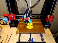
This is fully operational now.
Endstops were added, print and enjoy.
Update 10/23/2015:
Raised the bottom of the X carriage (hotend holder) by 1mm to give more space at the bottom of the hotend heatsink.
Uploaded the fan shroud, it is designed to use blower fans for the plastic active cooling and a 40mm x 40mm x 20mm normal 12v pc fan to cool the hotends, a standard 10mm fan does not move enough air to cool both heads at a time but the 20mm fan works great.
Uploaded a in progress fan duct, I have printed it a couple times for fit and am printing the final version of this style now for testing tomorrow.
I thought about using two fans on the hotend one to push one to pull, the ones I found though blow a lot of air and with both nozzles at 220c you can barely feel a warm breeze at the bottom and quite cool at the top, but it is getting cooler now, the test will be in the middle of a hot summer.
Here are the fans that I used.
2 - http://www.ebay.com/itm/321760495643
1 - http://www.amazon.com/gp/product/B006ODM76C
Update 11/2/2015
I have decided to do a dual Z lift system with a hardened linear shaft in each corner, that should eliminate all Z wobble and issues, and I am switching from a 1/4" thick aluminum build plate to a 1/8", the 1/4" would probably be fine with the dual Z but might as well lighten the weight and help the build platform to heat up faster.
I expected to have it all done last weekend but I forgot to get more M5 nuts and bolts as I ran out and in the US it costs me $1.50 for 2 bolts/screws from the hardware store since they are metric. :-(
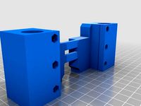
I was looking at everything and have decided to change the XY parts, right now they clamp the LME12UU bearing in place, sometimes that can throw the bearing out of alignment, I found that to be the case on the Z axis, it was bad. I decided to make a circular mount like you would get if you bought the brackets in metal, the metal ones you slide the bearing in and put a locking clip in, my new ones is completely encircled in plastic and you put two stop screws in the corners to keep the bearing from coming back out.
I left the v5 clamp ones posted and included the new v6 as a separate item for those that may not like that style, I printed it out and it aligned perfectly and worked really well, I am working on the X axis part now.
Update 11/16/2015
Uploaded all the new parts, it is working so much better, I will get pics up soon, just really busy.
I gave up on the bearing flanges, they were more trouble than they are worth, unless your printer prints perfectly which my original one didn't then you have imperfections in the inside of the flange where the belt rides and I had them pop apart and then the belt fall off several times, maybe PLA wouldn't pop apart but I was concerned about the temperature issues if I enclosed it.
What I did was to just do a bushing that the bearing sits between so the belt sits right on the perfectly round, and smooth bearing itself.
changing that has changed my prints to perfectly aligned perimeter layers, I am extremely happy with the prints.
I am going to tweak the XY motor mounts so that the bearings are a bit further in, finish the active cooling ducts, and I may add a z probe but lack of space it will probably be a switch driven probe and then I am going to consider this finished. (until I remember something else)
Update 11/23/2015:
All of the new parts are installed and everything is working beautifully.
All I have left on this project is the improve the active cooling ducts for the fans to cool PLA.
Uploaded new pictures.
see some print videos here
Update 11/29/2015:
Finished the airduct.
I tried many different styles but due to the tight spaces most were too close to the heaterblock and eventually melted and sagged.
I finally hit on a design that did not blow too much towards the bed or too much on the nozzle cooling it down.
Update 12/2/2015
I forgot to post the end stop magnet and hall effect holder for the Y axis.
The fan ducts still blew on the nozzle too much I modified it a little, and realized one fan didn't align due to the fact that the fan outlet is offset so I adjusted the duct for that side so print both a and b and then you will know which goes on which fan when the center lines up with the nozzles.
As far as I am concerned this is finalized, it works beautifully.
BUT.....Update 1/10/2016:
I just had a scathingly brilliant idea.
Aligning the heads to the same height is an absolute pain in the A** you have to loosen the clamp and twist the heatsink with some needle nosed pliers until the height is obtained, and trust me it is not fun.
I just had the idea of the clamp itself, on one side I will leave the clamp as is, on the other hotend I will shrink the inner part of the clamp by 1mm top and bottom so that you will have 2mm wiggle room, set the bed until nozzle one is touching, let nozzle 2 drop and touch the bed and then tighten the clamp, done.
Simple and easy, I guess there is a reason for the term KISS and trust me, this is so simple I really do feel stupid..... ;-)
With this change it is important to put the clamp in properly now, match thin side to thin side and thick to thick.
I do have some add on features for later but the core is done.
those features being a cable/boden holder and a z-probe.
I am working on a single head version of this setup, the X carriage and Y carriage will be different, I thought about making them universal but with a single nozzle I can squeeze extra build space out of it if I try, like 2" in one direction and 1" in another.
But I will do a Drop in single nozzle X carriage replacement for this setup as well.
Also I will be working on an 8mm version of both the dual and single head version
Update 3/19/2017:
Version 8 of the Dual Hotend:
I have switched to physical switches instead of hall effect as I was having issues with them and went back to old school.
One head is held snug, the other head can adjust +/- 1mm up and down to help to level the heads, loosen the clamp, bring the bed to just touch the set hotend and let the other hotend drop to the bed and then tighten the clamp, you are now aligned.
Added a BLTouch version.
Added a Inductive probe version with a lock screw to secure it in place. I used an LJ18A3-8-Z/BX
NEW option for the upper motor mounts.
either old mount or new will work but the new motor mount has been extended to hold a bearing to hold the top of the 12mm ball screw stable, I used 12mm x 28mm x 8mm 6001ZZ bearings, the bearing holder is adjustable.
Update 3/26/2017:
There was a problem with the belt mounts being too loose in one corner, fixed all of them.
I finished the fan shroud, it holds 2 30mm fans to cool the hotends, and 2 40mm fans for part cooling, I used 40x40x20mm fans for part cooling, the more air the better.
I moved the bearing screw holes as they were too close to the bearing throwing off alignment a little.
I modified the inductive probe version to us a clamp, a setscrew was just not cutting it, it would throw the probe into an angle when tightened.
Special thanks to Saldot and his Fan holder/mount for E3D v6 http://www.thingiverse.com/thing:780379 which I butchered into my fan shroud as I have been using his fan holder for quite a while and really like it.
Coming up next will be a tweak to the bearing holder motor mounts to make them a bit smaller and eventually be a single head version.
It does not cross over it runs at two different levels so everything stays straight.
I used 686Z bearings on the ends and the flanges I made are designed to be paused then the bearing added then printing to continue so they are encased in plastic (a blast of a heat gun before hitting resume makes a strong bond for the continuing layer.)
I made it around this hotend that I got from amazon:
Signswise Assembled J-head Hotend 0.4mm Nozzle Printer Head for 1.75mm Filamentshttp://www.amazon.com/Signswise-Assembled-J-head-Printer-Filaments/dp/B00SWLMWDM
It shouldn't take much to change the clamp to fit your hotend.
Things to do:
Motor mounts.
Corner bearing mounts.
Spot for a small magnet on the Y carriage for the X carriage home and another for Y homing.
Spot for a hall effect sensor on the X carriage to line up with above
Spot for a Z probe.
My thanks to Jayftee and Make-a-FaceI used Jay's bearing holder and part of Makes belt older.http://www.thingiverse.com/thing:195621http://www.thingiverse.com/thing:745934
Update 9/12/2015:
I had to redesign the X carriage, when I went to put it together it wasted almost 2 inches of space so I flipped the Y axises upside down to lift it up higher and to put the belts above the printer on top of the frame which solved the problem of no where to mount anything.
it is functional now, I was going to put new picks but I am almost done mounting everything and running the belts I just need to print out some more bearing flanges, on those I stop at height with cura, and pop the bearing in and resume printing.
I have made a motor mount that mounts to the outside on the sides with the belts passing through, I will have picks up hopefully by tomorrow as soon as I get the rest of the bearings done everything else is mounted, lines up and is ready to go.
Update 9/15/2015:
I finished assembling the mechanical parts, all seems to look good and moves as it should, I could have brought the corner bearings in more and use a t-nut in the slot and had them in line but I wanted more support than that offered and tapped the corner holes of the extruded aluminum and used nice long 1/4" bolts to hold it together, so it causes the belts to angle out to the corners but it shouldn't matter as it gets pulled away on one corner it gets pulled tighter on the other so there is never any slack and the other thing look at the serpentine belt on your car, it does not make a perfect square. ;-)
Pictures added, I just need to wire the motors to the smoothieboard now.
Update 9/25/2015:
I worked out where to put the endstops, I made them separate to glue on (acetone for the win) now that I have how I want them designed and best placement for them I will put them in the design of the parts so that they are built in.
I have everything hooked up but the hotends and the extruders and told it to print, told it to do a print speed of 150mm/s and a move speed of 300mm/s and it didn't blink an eye, I cranked it to 999% and it flew, I doubt it could push the plastic out that fast especially as I normally use a 0.3mm nozzle but the mechanism handled it just fine and flew, it was a glorious sight.
Update 10/9/2015:
This is fully operational now.
Endstops were added, print and enjoy.
Update 10/23/2015:
Raised the bottom of the X carriage (hotend holder) by 1mm to give more space at the bottom of the hotend heatsink.
Uploaded the fan shroud, it is designed to use blower fans for the plastic active cooling and a 40mm x 40mm x 20mm normal 12v pc fan to cool the hotends, a standard 10mm fan does not move enough air to cool both heads at a time but the 20mm fan works great.
Uploaded a in progress fan duct, I have printed it a couple times for fit and am printing the final version of this style now for testing tomorrow.
I thought about using two fans on the hotend one to push one to pull, the ones I found though blow a lot of air and with both nozzles at 220c you can barely feel a warm breeze at the bottom and quite cool at the top, but it is getting cooler now, the test will be in the middle of a hot summer.
Here are the fans that I used.
2 - http://www.ebay.com/itm/321760495643
1 - http://www.amazon.com/gp/product/B006ODM76C
Update 11/2/2015
I have decided to do a dual Z lift system with a hardened linear shaft in each corner, that should eliminate all Z wobble and issues, and I am switching from a 1/4" thick aluminum build plate to a 1/8", the 1/4" would probably be fine with the dual Z but might as well lighten the weight and help the build platform to heat up faster.
I expected to have it all done last weekend but I forgot to get more M5 nuts and bolts as I ran out and in the US it costs me $1.50 for 2 bolts/screws from the hardware store since they are metric. :-(
I was looking at everything and have decided to change the XY parts, right now they clamp the LME12UU bearing in place, sometimes that can throw the bearing out of alignment, I found that to be the case on the Z axis, it was bad. I decided to make a circular mount like you would get if you bought the brackets in metal, the metal ones you slide the bearing in and put a locking clip in, my new ones is completely encircled in plastic and you put two stop screws in the corners to keep the bearing from coming back out.
I left the v5 clamp ones posted and included the new v6 as a separate item for those that may not like that style, I printed it out and it aligned perfectly and worked really well, I am working on the X axis part now.
Update 11/16/2015
Uploaded all the new parts, it is working so much better, I will get pics up soon, just really busy.
I gave up on the bearing flanges, they were more trouble than they are worth, unless your printer prints perfectly which my original one didn't then you have imperfections in the inside of the flange where the belt rides and I had them pop apart and then the belt fall off several times, maybe PLA wouldn't pop apart but I was concerned about the temperature issues if I enclosed it.
What I did was to just do a bushing that the bearing sits between so the belt sits right on the perfectly round, and smooth bearing itself.
changing that has changed my prints to perfectly aligned perimeter layers, I am extremely happy with the prints.
I am going to tweak the XY motor mounts so that the bearings are a bit further in, finish the active cooling ducts, and I may add a z probe but lack of space it will probably be a switch driven probe and then I am going to consider this finished. (until I remember something else)
Update 11/23/2015:
All of the new parts are installed and everything is working beautifully.
All I have left on this project is the improve the active cooling ducts for the fans to cool PLA.
Uploaded new pictures.
see some print videos here
Update 11/29/2015:
Finished the airduct.
I tried many different styles but due to the tight spaces most were too close to the heaterblock and eventually melted and sagged.
I finally hit on a design that did not blow too much towards the bed or too much on the nozzle cooling it down.
Update 12/2/2015
I forgot to post the end stop magnet and hall effect holder for the Y axis.
The fan ducts still blew on the nozzle too much I modified it a little, and realized one fan didn't align due to the fact that the fan outlet is offset so I adjusted the duct for that side so print both a and b and then you will know which goes on which fan when the center lines up with the nozzles.
As far as I am concerned this is finalized, it works beautifully.
BUT.....Update 1/10/2016:
I just had a scathingly brilliant idea.
Aligning the heads to the same height is an absolute pain in the A** you have to loosen the clamp and twist the heatsink with some needle nosed pliers until the height is obtained, and trust me it is not fun.
I just had the idea of the clamp itself, on one side I will leave the clamp as is, on the other hotend I will shrink the inner part of the clamp by 1mm top and bottom so that you will have 2mm wiggle room, set the bed until nozzle one is touching, let nozzle 2 drop and touch the bed and then tighten the clamp, done.
Simple and easy, I guess there is a reason for the term KISS and trust me, this is so simple I really do feel stupid..... ;-)
With this change it is important to put the clamp in properly now, match thin side to thin side and thick to thick.
I do have some add on features for later but the core is done.
those features being a cable/boden holder and a z-probe.
I am working on a single head version of this setup, the X carriage and Y carriage will be different, I thought about making them universal but with a single nozzle I can squeeze extra build space out of it if I try, like 2" in one direction and 1" in another.
But I will do a Drop in single nozzle X carriage replacement for this setup as well.
Also I will be working on an 8mm version of both the dual and single head version
Update 3/19/2017:
Version 8 of the Dual Hotend:
I have switched to physical switches instead of hall effect as I was having issues with them and went back to old school.
One head is held snug, the other head can adjust +/- 1mm up and down to help to level the heads, loosen the clamp, bring the bed to just touch the set hotend and let the other hotend drop to the bed and then tighten the clamp, you are now aligned.
Added a BLTouch version.
Added a Inductive probe version with a lock screw to secure it in place. I used an LJ18A3-8-Z/BX
NEW option for the upper motor mounts.
either old mount or new will work but the new motor mount has been extended to hold a bearing to hold the top of the 12mm ball screw stable, I used 12mm x 28mm x 8mm 6001ZZ bearings, the bearing holder is adjustable.
Update 3/26/2017:
There was a problem with the belt mounts being too loose in one corner, fixed all of them.
I finished the fan shroud, it holds 2 30mm fans to cool the hotends, and 2 40mm fans for part cooling, I used 40x40x20mm fans for part cooling, the more air the better.
I moved the bearing screw holes as they were too close to the bearing throwing off alignment a little.
I modified the inductive probe version to us a clamp, a setscrew was just not cutting it, it would throw the probe into an angle when tightened.
Special thanks to Saldot and his Fan holder/mount for E3D v6 http://www.thingiverse.com/thing:780379 which I butchered into my fan shroud as I have been using his fan holder for quite a while and really like it.
Coming up next will be a tweak to the bearing holder motor mounts to make them a bit smaller and eventually be a single head version.
Similar models
thingiverse
free

Modified x-carriage and Nozzle-mounting by yzorg
...r to the parts later... or maybe i design airchannels to reuse the air from the active-cold-end directing it to the print surface
thingiverse
free

Dual E3D bowden coldend with 50mm fan cooling print and hotends by Nilz
... the e3d fans and don't want to cool the print, and a version which can hold an inductive sensor as an accurate z-endswitch .
thingiverse
free

Kossel Mini Effector for E3D V5 Hotend by AlexBorro
... hotend has a tight fit into the effector.
if you prefer clamping, just print 2 clamps and fasten with 2x m3x16mm bolts and nuts.
thingiverse
free
Anet A8 E3D V6 Mount by Brisemuth
...an. it shouldn't cool down the hotend but a bigger surface around the nozzle.
any comments are appreciated.
cheers,
brisemuth
thingiverse
free

Servo Mount for Z probe on x carriage by MichaelM223
...n fit nicely at any point you can attach a fan.
a modified z-probe arm is still in the works :)
edit
added modified z-probe arm
thingiverse
free

chimera fan mount by bradyhoover_designs
...f slightly less direct cooling from the right duct.
have fun printing and get those overhangs better with more efficient cooling.
thingiverse
free

Prusa X Carriage with integrated Z Probe and Fan Holder by mblaster
...crew and tends to wobble around a bit, but as the arm is pressed against the carriage the probing precision is still really good.
thingiverse
free

Matt's minimalistic j-head mount (v7) by Mateusz
...v3:
moved up by another 1.5cm
slim down design, better positioning of belt clamps, added one belt clamp
fans mount straight
thingiverse
free
Anycubic I3 Z-Carriage upgrade by Deadsnale
...work well.
if you have any questions please let me know in the comments. if you print them and please let me know how they work.
thingiverse
free
Funbot Y-Carriage & Z-carriage 8mm with bearing clamps by Wolfire18
...check the tolerances, if you want to print the test pieces too before going for this one you can find them under the remixed tab.
Lme12Uu
thingiverse
free

LME12UU Bushing by Affordable3D
...aring in this size, a printed alternative works great here. i used a diamond file to sand the sliding surface to a smooth finish.
thingiverse
free

LME12UU_to_LMK12UU_Adapter by Max68
...lme12uu_to_lmk12uu_adapter by max68
thingiverse
bearing adapter lme12uu in lmk12uu
thingiverse
free
![Printrbot + Upgrades [X-bridge, Extruder Mount, Y-Clips...] by PolakiumEngineering](/t/9050552.jpg)
Printrbot + Upgrades [X-bridge, Extruder Mount, Y-Clips...] by PolakiumEngineering
...with 28mm 36 tooth gt2 pulley 10/09/12 - added lme12uu compatible parts. (see notes) 03/01/13 - replaced by...
thingiverse
free

Wider PrintrBot Base and 12mm Z axis, Stylized by morrisgunn
...it is designed to hold 12mm z rods and lme12uu bearings from vxb. i have stylized the parts i...
thingiverse
free

Hypercube evolution 12mm XY modification by sverreb
...axis rods. the x-carriage is designed to use igus lme12uu compatible bearings as it is assumed that a carbon...
thingiverse
free

#2 Cuisenare on a LeHof by shivinteger
...[3] thing title : dual corexy setup that uses lme12uu and 12mm shafts [3] thing url : http://www.thingiverse.com/thing:990244 [3]...
thingiverse
free

ROB-O Junior FFF 3D Printer using 80/20s 10/10 (1"x1") extrusion by Thump2010
...new z-axis, new z-coupler, 12mm clamps, psu mounts, and lme12uu to lmk12uu adapter. i am not using the z-axis...
grabcad
free

Cuscinetti lineari LME5UU LME8UU LME10UU LME12UU LME16UU LME20UU
...ted with solidworks with simplified passage. for complete measurements see lme datasheet.pdf.
solidworks parts files are included
Thump2010
thingiverse
free
XHOVER WIN3 SMA Mount by Thump2010
...3 sma mount by thump2010
thingiverse
a friend asked me to make an sma mount for his xhover win 3" frame.
f3d file included.
thingiverse
free
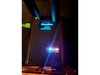
Duplex Ham Radio Hotspot by Thump2010
...spot.
put the hotspot hat together with the raspberry pi and then put it in the case.
the screws are m2, you will need 6 of them.
thingiverse
free

Malyan M180 Spool Holder by Thump2010
...use but being the same height as the originals and designed to used the bearings from the original holders.
added a 58 mm version
thingiverse
free

Box fan foot by Thump2010
...ould have been better with pla probably.
either way it worked well, fan is nice and stable now.
(forgive the z wobble in my pics)
thingiverse
free

Baby Bottle Disposable Liner Dispensor by Thump2010
... doesn't touch that part as the bottle is in the way, and the inside is protected by the other liners and the lid on the top.
thingiverse
free

Spin Brush sander by Thump2010
... is almost eight years old, who knows if they have changed since then.
here is a video of it working https://youtu.be/b9w12flegwe
thingiverse
free

Anycubic Linear Plus PSU Mount by Thump2010
...lel to the bottom edges instead of straight across the corner.
it uses the screws and nuts that come with the original psu mount.
thingiverse
free

FXT Viper Antenna Thumbscrew by Thump2010
...5.06: print setup → quality → horizontal expansion
simplify3d 3.x: other → dimensional adjustments → horizontal size compensation
thingiverse
free

Parametric Lipo Battery Protector by Thump2010
...eed to change the fusion 360 parameters mentioned above.
bonus feature: it gives the quad a very nice and flat surface to sit on.
thingiverse
free
Low profile RC transmitter wall hanger by Thump2010
...y hang an rc transmitter with a kickstand.
it was designed in fusion 360 but it is not parametric, just drawn. f3d file included.
Corexy
thingiverse
free
CoreXY by Kaz_tech
...corexy by kaz_tech
thingiverse
this is the model of corexy platform. i separately put the parts on this place.
thingiverse
free

corexy plotter by tjwan
...corexy plotter by tjwan
thingiverse
parts for corexy mill inspired by http://der-frickler.net/technik/corexyportal
thingiverse
free
ScribbleJ CoreXY Beta by ScribbleJ
...j/corexy-v1https://github.com/scribblej/corexy-v1#corexy-beta
full gallery of development photos here: http://imgur.com/a/donun
thingiverse
free
CoreXY Emblem by emkajot
...by emkajot
thingiverse
an emblem for your corexy printer.
size: 100mm x 38mm x 2mm.
update: added a version with a proper mount.
thingiverse
free

SolidCore CoreXY Carriage by shanehooper
...olidcore 3d printer. this design could be used in other corexy 3d printers.
also see:https://3ddistributed.com/corexy-3d-printer/
thingiverse
free
CoreXY 3D Printer Model by ReginaFabricam
...bricam
thingiverse
this is an original design of a corexy printer.https://www.tinkercad.com/things/jggr9qk4s4p-3d-printer-corexy
thingiverse
free

coreXY Upper structure Left
...corexy upper structure left
thingiverse
my customized corexy 3d printer upper left parts
thingiverse
free
CoreXY by frankie
...ing machines, etc. the design is described in greater detail at http://www.corexy.com . a video is at http://vimeo.com/40914530 .
thingiverse
free

Endstop block for CoreXY carriage by svkeulen
...endstop block for corexy carriage by svkeulen
thingiverse
endstop for corexy carriage
thingiverse
free
X carriage for the CoreXY MGN12 by hackerbijay
...x carriage for the corexy mgn12 by hackerbijay
thingiverse
x carriage for the corexy frame
12Mm
turbosquid
$30

Settings 4mm to 12mm
...oyalty free 3d model settings 4mm to 12mm for download as 3dm on turbosquid: 3d models for games, architecture, videos. (1548862)
3d_export
$10

A box of bullets of 12mm caliber
...a box of bullets of 12mm caliber
3dexport
a box of 12mm caliber bullets for hunting small game and poultry.
turbosquid
$7

Straight chisel 12mm
... chisel 12mm for download as max, 3ds, dae, dwg, fbx, and obj on turbosquid: 3d models for games, architecture, videos. (1601806)
turbosquid
$7
Straight chisel 12mm
... chisel 12mm for download as max, 3ds, dae, dwg, fbx, and obj on turbosquid: 3d models for games, architecture, videos. (1601075)
turbosquid
$1

Linear Bearing 12mm ID
... available on turbo squid, the world's leading provider of digital 3d models for visualization, films, television, and games.
turbosquid
$1
Rc Paddle Tire 12mm hex
... available on turbo squid, the world's leading provider of digital 3d models for visualization, films, television, and games.
3d_export
free

fifa world cup qatar 2022
...of the magnet for the stand( diameter 52mm, height 12mm, the magnet in the ground(diameter 30mm, height...
3d_ocean
$8

Roche Bobois - Tenere Coffee Table
...table tenere roche bobois – tenere coffee table – 12mm glued glass top, frame in concrete effect finish, single...
3d_export
$10
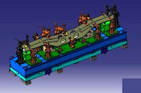
welding fixture for side beam of train bogie
...vertical plate wall thickness is 14mm, the web is 12mm and the middle sections are distributed with 10mm reinforced...
3d_export
$10

bracelet clasp lock12mm x 24mm
...ach others and then enjoy your bracelet. i don't recommend to rescale this model, order to create the lock same as your wish.
Dual
turbosquid
free

Dual Pistols
...ls
turbosquid
free 3d model dual pistols for download as fbx on turbosquid: 3d models for games, architecture, videos. (1320360)
turbosquid
$2
Dual Axe
...urbosquid
royalty free 3d model dual axe for download as fbx on turbosquid: 3d models for games, architecture, videos. (1332372)
turbosquid
$10
Dual Lesaths
... available on turbo squid, the world's leading provider of digital 3d models for visualization, films, television, and games.
3ddd
$1
плитка Dual Bianco (Испания)
...й плитки venis dual (испания). технические качества: устойчивость к стирания, отличная геометрия, отсутствие проблем при укладке.
turbosquid
$35

Dual Mesh Fonts
...ree 3d model dual mesh fonts for download as ma, obj, and fbx on turbosquid: 3d models for games, architecture, videos. (1352989)
turbosquid
$29

Dual Flask with Bungs
...del dual flask with bungs for download as obj, fbx, and blend on turbosquid: 3d models for games, architecture, videos. (1210512)
turbosquid
$19
Dual Socket Plug
...3d model dual socket plug for download as obj, fbx, and blend on turbosquid: 3d models for games, architecture, videos. (1303912)
turbosquid
$13
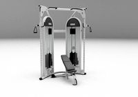
Dual Adjustable Pulley
... available on turbo squid, the world's leading provider of digital 3d models for visualization, films, television, and games.
turbosquid
$10

Amoi N809 Dual
... available on turbo squid, the world's leading provider of digital 3d models for visualization, films, television, and games.
turbosquid
$5
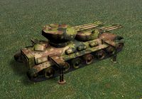
Dual Turret Tank
... available on turbo squid, the world's leading provider of digital 3d models for visualization, films, television, and games.
Shafts
3d_export
$5
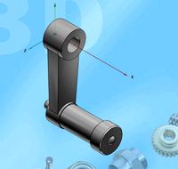
shaft handle
...shaft handle
3dexport
shaft handle
3d_export
$5

shaft bracket
...shaft bracket
3dexport
shaft bracket
turbosquid
$3

Shaft
... available on turbo squid, the world's leading provider of digital 3d models for visualization, films, television, and games.
turbosquid
$2

shaft
... available on turbo squid, the world's leading provider of digital 3d models for visualization, films, television, and games.
3d_export
free
crank shaft
...crank shaft
3dexport
crank shaft with piston with different materials
3d_export
$8
shaft bearing
...shaft bearing
3dexport
shaft bearing m10, m12,m16, m20 and m27
3d_export
$5
hexagonal shaft knob
...hexagonal shaft knob
3dexport
hexagonal shaft knob
3d_export
$5
shaft hand wheel
...shaft hand wheel
3dexport
shaft hand wheel
3d_export
$5
triangular shaft knob
...triangular shaft knob
3dexport
triangular shaft knob
3d_export
$5
octagonal shaft knob
...octagonal shaft knob
3dexport
octagonal shaft knob
Setup
3d_ocean
$5
Light Setup
...
3docean
light setup lightbox lights render setup
that’s light setup. easy for use. just delete spheres and position your object!
turbosquid
free
Desk setup
...oyalty free 3d model desk setup for download as fbx and blend on turbosquid: 3d models for games, architecture, videos. (1300745)
turbosquid
free
the library.max(setup)
... available on turbo squid, the world's leading provider of digital 3d models for visualization, films, television, and games.
3d_ocean
$5

HDRI Studio Lighting Setup
...ate the hdri into many lighting combinations. increase/decrease intensity. this is the complete lighting setup for vray using ...
3d_ocean
$9

Fireworks - Render Setup
...can be used for any kinds of short movies, or other works. includes a well documentation which includes the steps to change th...
3d_ocean
$5

MentalRay Studio Lighting Setup
...ene which you can change. the colors of the lights are ofcourse tweak-able. this is a basic light setup for you to use for pro...
3d_ocean
$5

Vray scene setup
...studio scene 2. vray setup 3. 2 vray cameras, one of them with dof 4. vray lights 5. vitra panton chair model 6. photoshop fil...
3d_ocean
$15
Render Setups Chair Wall
...render setups chair wall
3docean
chair max render setups vray wall white
render setups chair wall
turbosquid
$25

Interior light setup
...oyalty free 3d model interior light setup for download as c4d on turbosquid: 3d models for games, architecture, videos. (1539984)
turbosquid
$1
basic pc setup
...d
royalty free 3d model basic pc setup for download as blend on turbosquid: 3d models for games, architecture, videos. (1650020)
Uses
3ddd
$1

US flag
...us flag
3ddd
флаг
us flag
3d_export
free

Among us
...among us
3dexport
among us red
3d_export
free

Among Us
...among us
3dexport
this 3d-model of a character from the game "among us". it can be used as a toy or decoration.
3d_export
$6

among us
...among us
3dexport
doll from among us in red
3d_export
$5

amoung us
...amoung us
3dexport
amoung us character. was created by cinema 4d 19
3d_export
$5
Humvee us
...humvee us
3dexport
humvee us 3d model good quality for animation
3d_export
$15

among us
...among us
3dexport
turbosmooth modifier can be used to increase mesh resolution if necessary
3d_export
$25

mailbox us
...mailbox us
3dexport
low poly model mailbox us. modeling in the blender, texturing in substance painter
design_connected
$13
Use Me
...use me
designconnected
sitland use me computer generated 3d model. designed by paolo scagnellato.
3d_export
$5

Among Us
...rt
the among us model comes in a variety of colors that can be customized by anyone, and even works with little in the animation