Thingiverse
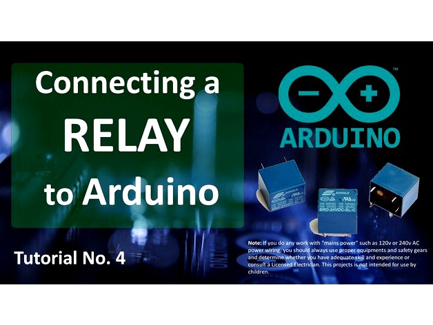
DRIVING A RELAY WITH AN ARDUINO by tarantula3
by Thingiverse
Last crawled date: 3 years ago
DRIVING A RELAY WITH AN ARDUINO
Hello everyone, welcome back to my channel. This is my 4th tutorial on how to drive a RELAY (not a relay module) with an Arduino.
There are hundreds of tutorial available on how to use a "relay module" but I could not find a good one that shows how to use a Relay and not a Relay module. So, here we are to discuss how a relay works and how we can hook it up to an Arduino.
Note: If you do any work with "mains power" such as 120v or 240v AC power wiring, you should always use proper equipments and safety gears and determine whether you have adequate skill and experience or consult a Licensed Electrician. This projects is not intended for use by children.
Step 1: Basics
A Relay is a large mechanical switch, which is toggled on or off by energizing a coil.
Depending on the operating principle and structural features relays are of different types, such as:
Electromagnetic Relays
Solid State Relays
Thermal Relays
Power Varied Relays
Reed Relays
Hybrid Relays
Multi-dimensional Relays and so on, with varied ratings, sizes and applications.
However, in this tutorial we will only be discussing about an electromagnetic relays.
Guide to Different Types of Relays:
https://en.wikipedia.org/wiki/Relay
https://www.elprocus.com/different-types-of-relays...
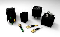
Step 2: My Relay (SRD-05VDC-SL-C)
The relay I am looking at is a SRD-05VDC-SL-C. It is very popular relay among Arduino and DIY electronics hobbyists.
This relay has 5 pins. 2 for the coil. Middle one is COM (common) and the rest of the two are called NO (Normally Open) and NC (Normally Close). When current flows through the coil of the relay, a magnetic field is created that causes a ferrous armature to move, either making or breaking an electrical connection. When the electromagnet is energized the NO is the one which is on and NC is the one which is off. When the coil is de-energized the electromagnetic force disappears and the armature moves back to the original position turning on the NC contact. The closing and releasing of the contacts results in powering on and off of the circuits.
Now, if we look at the top of the relay the first thing we see is SONGLE, it is the name of the manufacturer. Then we see the "Current and Voltage Rating": it is the maximum current and/or voltage that can be passed through the switch. It starts from 10A@250VAC and goes down till 10A@28VDC Finally the bottom bit says: SRD-05VDC-SL-C SRD: is the model of relay. 05VDC: Also known as "Nominal Coil Voltage" or "Relay Activation Voltage", it is the voltage necessary for the coil to activate the relay.
S: Stands for "Sealed Type" structure
L: is the "Coil Sensitivity" which is 0.36W
C: tells us about the contact form
I have attached the datasheet of the relay for more information.http://old.ghielectronics.com/downloads/man/20084...
Step 3: Getting Hands on a Relay
Let’s start by determining the relay coil pins.
You can do it either by connecting a multimeter to resistance measuring mode with a scale of 1000 ohm (since the coil resistance normally ranges between 50 ohm and 1000 ohm) or by using a battery. This relay has 'no' polarity marked on it since the internal suppressing diode is not present in it. Hence, the positive output of DC power supply can be connected to any one of the coil pins while negative output of DC power supply will be connected to the other pin of the coil or vice versa. If we connect our battery to the right pins you can actually hear the clicking sound when the switch turns on.
If you ever get confused in figuring out which one is NO and which one is NC pin, follow the steps below to easily determine that:
Set the multimeter to resistance measuring mode.
Turn the relay upside-down to see pins located at its bottom part.
Now connect one on the multimeter's probe to the pin in between the coils (Common Pin)
Then connect the other probe one by one to the remaining 2 pins.
Only one of the pins will complete the circuit and will show activity on the multimeter.
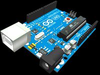
Step 4: Arduino and a Relay
The question is "Why to use a relay with an Arduino?"
A micro controller's GPIO (general purpose input/output) pins cannot handle higher power devices. A LED is easy enough, but large power items such as light bulbs, motors, pumps or fans required more sneaky circuitry. You can use a 5V relay to switch the 120-240V current and use the Arduino to control the relay.
A relay basically allows a relatively low voltage to easily control higher power circuits. A relay accomplishes this by using the 5V outputted from an Arduino pin to energize the electromagnet which in turn closes an internal, physical switch to turn on or off a higher power circuit. The switching contacts of a relay are completely isolated from the coil, and hence from the Arduino. The only link is by the magnetic field. This process is called "Electrical Isolation".
Now a question arises, Why do we need the extra bit of circuit to drive the relay? The coil of the relay needs a large current (around 150mA) to drive the relay, which an Arduino cannot provide. Therefore we need a device to amplify the current. In this project the NPN transistor 2N2222 drives the relay when the NPN junction gets saturated.
Step 5: Hardware Requirement
For this tutorial we need:
1 x Breadboard
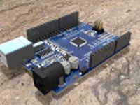
1 x Arduino Nano/UNO (Whatever is handy)
1 x Relay
1 x 1K resistor
1 x 1N4007 High Voltage, High Current Rated Diode to protect the micro-controller from voltage spikes
1 x 2N2222 General purpose NPN transistor
1 x LED and a 220 ohm current limiting resistor to test the connectivity
Few connecting cables
A USB cable to upload the code to the Arduino
and general soldering equipments
Step 6: Assembly
Lets start by connecting the VIN and GND pins of the Arduino to the +ve and -ve rails of the breadboard.
Then connect one of the coils pin to the +ve 5v rail of breadboard.
Next we need to connect a diode across the electromagnetic coil. The diode across the electromagnet conducts in the reverse direction when the transistor is turned off to protect against a voltage spike or the backward flow of current.
Then connect the Collector of the NPN transistor to the 2nd pin of the coil.
The Emitter connects to the -ve rail of the breadboard.
Final, using a 1k resistor connect the Base of the transistor to the D2 pin of the Arduino.
Thats it our circuit is complete, now we can upload the code to the Arduino to turn on or off the relay. Basically, when +5v flow through the 1K resistor to the Base of transistor, a current of about .0005 amps (500 microamps) flows and turns on the transistor. A current of about .07 amps starts flowing through the junction turning on the electromagnet. The electromagnet then pulls the switching contact and moves it to connect the COM terminal to the NO terminal.
Once the NO terminal is connected a Lamp or any other load can be turned on. In this example I am just turning on and off a LED.
Step 7: The Code
The code is very simple. Just start by defining the digital pin number 2 of the Arduino as the Relay pin.
Then define the pinMode as OUTPUT in the setup section of the code. Finally, in the loop section we are going to turn on and off the relay after every 500 CPU cycles by setting the Relay pin to HIGH and LOW respectively.
Step 8: Conclusion
Remember: It is very important to place a diode across the coil of the relay because a spike of voltage (inductive kickback from the coil) is generated (Electromagnetic Interference) when the current is removed from the coil due to the collapse of the magnetic field. This voltage spike can damage the sensitive electronic components controlling the circuit.
Most Important: Same as capacitors, we always under-rate the relay to mitigate the risk of relay failures. Lets say, you need to work at 10A@120VAC, don’t use a relay rated for 10A@120VAC, instead use a bigger one such as 30A@120VAC. Remember, power = current * voltage so a 30A@220V relay can handle up to a 6,000W device.
If you just replace the LED with any other electrical device like fan, bulb, fridge etc., you should be able to turn that appliance into a smart device with an Arduino controlled power outlet.
Relay can also be used to turn on or off two circuits. One when the electromagnet is on and the second one when the electromagnet is off.
A Relay helps in Electrical Isolation. The switching contacts of a relay are completely isolated from the coil, and hence from the Arduino. The only link is by the magnetic field.
Note: Short circuits on Arduino pins, or attempting to run high current devices from it, can damage or destroy the output transistors in the pin, or damage the entire AtMega chip. Often this will result in a "dead" pin of the micro-controller but the remaining chip will still function adequately. For this reason it is a good idea to connect OUTPUT pins to other devices with 470Ω or 1k resistors, unless maximum current draw from the pins is required for a particular application
Step 9: Thanks
Thanks again for watching this video! I hope it helps you. If you want to support me, you can subscribe to my channel and watch my other videos. Thanks, ca again in my next video.
Hello everyone, welcome back to my channel. This is my 4th tutorial on how to drive a RELAY (not a relay module) with an Arduino.
There are hundreds of tutorial available on how to use a "relay module" but I could not find a good one that shows how to use a Relay and not a Relay module. So, here we are to discuss how a relay works and how we can hook it up to an Arduino.
Note: If you do any work with "mains power" such as 120v or 240v AC power wiring, you should always use proper equipments and safety gears and determine whether you have adequate skill and experience or consult a Licensed Electrician. This projects is not intended for use by children.
Step 1: Basics
A Relay is a large mechanical switch, which is toggled on or off by energizing a coil.
Depending on the operating principle and structural features relays are of different types, such as:
Electromagnetic Relays
Solid State Relays
Thermal Relays
Power Varied Relays
Reed Relays
Hybrid Relays
Multi-dimensional Relays and so on, with varied ratings, sizes and applications.
However, in this tutorial we will only be discussing about an electromagnetic relays.
Guide to Different Types of Relays:
https://en.wikipedia.org/wiki/Relay
https://www.elprocus.com/different-types-of-relays...
Step 2: My Relay (SRD-05VDC-SL-C)
The relay I am looking at is a SRD-05VDC-SL-C. It is very popular relay among Arduino and DIY electronics hobbyists.
This relay has 5 pins. 2 for the coil. Middle one is COM (common) and the rest of the two are called NO (Normally Open) and NC (Normally Close). When current flows through the coil of the relay, a magnetic field is created that causes a ferrous armature to move, either making or breaking an electrical connection. When the electromagnet is energized the NO is the one which is on and NC is the one which is off. When the coil is de-energized the electromagnetic force disappears and the armature moves back to the original position turning on the NC contact. The closing and releasing of the contacts results in powering on and off of the circuits.
Now, if we look at the top of the relay the first thing we see is SONGLE, it is the name of the manufacturer. Then we see the "Current and Voltage Rating": it is the maximum current and/or voltage that can be passed through the switch. It starts from 10A@250VAC and goes down till 10A@28VDC Finally the bottom bit says: SRD-05VDC-SL-C SRD: is the model of relay. 05VDC: Also known as "Nominal Coil Voltage" or "Relay Activation Voltage", it is the voltage necessary for the coil to activate the relay.
S: Stands for "Sealed Type" structure
L: is the "Coil Sensitivity" which is 0.36W
C: tells us about the contact form
I have attached the datasheet of the relay for more information.http://old.ghielectronics.com/downloads/man/20084...
Step 3: Getting Hands on a Relay
Let’s start by determining the relay coil pins.
You can do it either by connecting a multimeter to resistance measuring mode with a scale of 1000 ohm (since the coil resistance normally ranges between 50 ohm and 1000 ohm) or by using a battery. This relay has 'no' polarity marked on it since the internal suppressing diode is not present in it. Hence, the positive output of DC power supply can be connected to any one of the coil pins while negative output of DC power supply will be connected to the other pin of the coil or vice versa. If we connect our battery to the right pins you can actually hear the clicking sound when the switch turns on.
If you ever get confused in figuring out which one is NO and which one is NC pin, follow the steps below to easily determine that:
Set the multimeter to resistance measuring mode.
Turn the relay upside-down to see pins located at its bottom part.
Now connect one on the multimeter's probe to the pin in between the coils (Common Pin)
Then connect the other probe one by one to the remaining 2 pins.
Only one of the pins will complete the circuit and will show activity on the multimeter.
Step 4: Arduino and a Relay
The question is "Why to use a relay with an Arduino?"
A micro controller's GPIO (general purpose input/output) pins cannot handle higher power devices. A LED is easy enough, but large power items such as light bulbs, motors, pumps or fans required more sneaky circuitry. You can use a 5V relay to switch the 120-240V current and use the Arduino to control the relay.
A relay basically allows a relatively low voltage to easily control higher power circuits. A relay accomplishes this by using the 5V outputted from an Arduino pin to energize the electromagnet which in turn closes an internal, physical switch to turn on or off a higher power circuit. The switching contacts of a relay are completely isolated from the coil, and hence from the Arduino. The only link is by the magnetic field. This process is called "Electrical Isolation".
Now a question arises, Why do we need the extra bit of circuit to drive the relay? The coil of the relay needs a large current (around 150mA) to drive the relay, which an Arduino cannot provide. Therefore we need a device to amplify the current. In this project the NPN transistor 2N2222 drives the relay when the NPN junction gets saturated.
Step 5: Hardware Requirement
For this tutorial we need:
1 x Breadboard
1 x Arduino Nano/UNO (Whatever is handy)
1 x Relay
1 x 1K resistor
1 x 1N4007 High Voltage, High Current Rated Diode to protect the micro-controller from voltage spikes
1 x 2N2222 General purpose NPN transistor
1 x LED and a 220 ohm current limiting resistor to test the connectivity
Few connecting cables
A USB cable to upload the code to the Arduino
and general soldering equipments
Step 6: Assembly
Lets start by connecting the VIN and GND pins of the Arduino to the +ve and -ve rails of the breadboard.
Then connect one of the coils pin to the +ve 5v rail of breadboard.
Next we need to connect a diode across the electromagnetic coil. The diode across the electromagnet conducts in the reverse direction when the transistor is turned off to protect against a voltage spike or the backward flow of current.
Then connect the Collector of the NPN transistor to the 2nd pin of the coil.
The Emitter connects to the -ve rail of the breadboard.
Final, using a 1k resistor connect the Base of the transistor to the D2 pin of the Arduino.
Thats it our circuit is complete, now we can upload the code to the Arduino to turn on or off the relay. Basically, when +5v flow through the 1K resistor to the Base of transistor, a current of about .0005 amps (500 microamps) flows and turns on the transistor. A current of about .07 amps starts flowing through the junction turning on the electromagnet. The electromagnet then pulls the switching contact and moves it to connect the COM terminal to the NO terminal.
Once the NO terminal is connected a Lamp or any other load can be turned on. In this example I am just turning on and off a LED.
Step 7: The Code
The code is very simple. Just start by defining the digital pin number 2 of the Arduino as the Relay pin.
Then define the pinMode as OUTPUT in the setup section of the code. Finally, in the loop section we are going to turn on and off the relay after every 500 CPU cycles by setting the Relay pin to HIGH and LOW respectively.
Step 8: Conclusion
Remember: It is very important to place a diode across the coil of the relay because a spike of voltage (inductive kickback from the coil) is generated (Electromagnetic Interference) when the current is removed from the coil due to the collapse of the magnetic field. This voltage spike can damage the sensitive electronic components controlling the circuit.
Most Important: Same as capacitors, we always under-rate the relay to mitigate the risk of relay failures. Lets say, you need to work at 10A@120VAC, don’t use a relay rated for 10A@120VAC, instead use a bigger one such as 30A@120VAC. Remember, power = current * voltage so a 30A@220V relay can handle up to a 6,000W device.
If you just replace the LED with any other electrical device like fan, bulb, fridge etc., you should be able to turn that appliance into a smart device with an Arduino controlled power outlet.
Relay can also be used to turn on or off two circuits. One when the electromagnet is on and the second one when the electromagnet is off.
A Relay helps in Electrical Isolation. The switching contacts of a relay are completely isolated from the coil, and hence from the Arduino. The only link is by the magnetic field.
Note: Short circuits on Arduino pins, or attempting to run high current devices from it, can damage or destroy the output transistors in the pin, or damage the entire AtMega chip. Often this will result in a "dead" pin of the micro-controller but the remaining chip will still function adequately. For this reason it is a good idea to connect OUTPUT pins to other devices with 470Ω or 1k resistors, unless maximum current draw from the pins is required for a particular application
Step 9: Thanks
Thanks again for watching this video! I hope it helps you. If you want to support me, you can subscribe to my channel and watch my other videos. Thanks, ca again in my next video.
Similar models
thingiverse
free

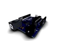
Relais Box (with SRD-05VDC-SL-C)
...d-05vdc-sl-c)
thingiverse
relais box
relais : srd-05vdc-sl-c
low level trigger (5v)
to control high voltage devices (10v 250vac)
grabcad
free

Solar Charger PCB
...n turns on grounding to the output of lm 317 to stop charging.
source : http://www.circuitdiagram.org/led_light_circuits_2.html
thingiverse
free

SRD Relai Arduino SRD 05VDC SL C
...srd relai arduino srd 05vdc sl c
thingiverse
small srd box
thingiverse
free

Songle Relay SPDT MODEL by WayneWeng
...odel by wayneweng
thingiverse
a relay 3d model of songle 5 pin srd-05vdc-sl-c.
songle relay spdt model.
step file available.
3dwarehouse
free

Variable impedance circuit
... of the transistor is varied with excellent linearity in accordance with the value of the voltage of the variable voltage source.
grabcad
free

SPDT-SRD-05VDC-SL-C
...spdt-srd-05vdc-sl-c
grabcad
relay spdt-srd-05vdc-sl-c
thingiverse
free

Arduino Relay Circuit by jmsstewart
...ino connect to both ground from relay power supply and ground from relay board. be welcome to modify and redistribute this board.
grabcad
free

HUIMU INDUSTRIAL GJ-5FA-L Relay
...op ● low-impedance mosfet as the output component minimize the total power consumption ● british standard pcb mounting dimensions
grabcad
free

Relay SRD -05VDC-SL-C
...c-sl-c
grabcad
relay to control mostly high voltage
my youtube channel
https://www.youtube.com/channel/uc0jdxs3vlhoscgesqug5oba
grabcad
free

Songle Relay SRD-05VCD-SL-C
...h connections for normally open (no), common (com) and normally closed (nc). the relay works with control signals of 3.3v and 5v.
Tarantula3
thingiverse
free
USING AN LDR SENSOR WITH ARDUINO by tarantula3
.... if you want to support me, you can subscribe to my channel and watch my other videos. thanks, ca again in my next instructable.
thingiverse
free

DIY - SOLAR BATTERY CHARGER by tarantula3
...lps you. if you want to support me, you can subscribe to my channel and watch my other videos. thanks, ca again in my next video.
thingiverse
free

DIY - ARDUINO BASED CAR PARKING ASSISTANT by tarantula3
...lps you. if you want to support me, you can subscribe to my channel and watch my other videos. thanks, ca again in my next video.
Relay
turbosquid
$50
Relay Spaceship
... model relay spaceship for download as skp, 3ds, dae, and obj on turbosquid: 3d models for games, architecture, videos. (1655800)
3ddd
$1

Scavolini / Grand Relais
...scavolini / grand relais
3ddd
scavolini
scavolini модель grand relais дизайн gianni pareschi
3ddd
$1

Сантехника Globo Relais
... унитаз , зеркало
сантехника globo relais
умывальник,зеркало,унитаз.
3d_export
$8
relay automatic assembly line
...relay automatic assembly line
3dexport
relay automatic assembly line
3ddd
free

Унитаз и биде Relais
... биде , унитаз
унитаз art.re001 bi и биде art.re009 bi
turbosquid
free

Relay 8 pin
... available on turbo squid, the world's leading provider of digital 3d models for visualization, films, television, and games.
cg_studio
$110

Power relay station3d model
...el
cgstudio
.3ds .fbx .max .obj - power relay station 3d model, royalty free license available, instant download after purchase.
3ddd
$1

Стол обеденный -Scavolini- Grand Relais
...s
3ddd
обеденный , scavolini
обеденный стол scavolini - grand relais, в трёх расцветках.
3d_export
$10
relay jd1912 12v 40a with connector
...lowing bodies: 1. relay jd1912 12v 40a - 1 piece; 2. connector housing - 1 piece; 3. terminal with a part of the wire - 4 pieces.
3ddd
free

Globo Relais furnitures
... , раковина
раковина с консолью st070.ne
зеркалоsp070.bi
стакан re0381x
мыльница re0391x
Arduino
turbosquid
$7
Arduino
...turbosquid
royalty free 3d model arduino for download as max on turbosquid: 3d models for games, architecture, videos. (1197165)
turbosquid
$3
Arduino
...turbosquid
royalty free 3d model arduino for download as c4d on turbosquid: 3d models for games, architecture, videos. (1305484)
3d_export
$5
arduino satellite
...rt
this model is the exact arduino based satellite model with some basic sensors and camera modules and also includes batteries.
turbosquid
$1
Arduino UNO
...alty free 3d model arduino uno for download as , stl, and wrl on turbosquid: 3d models for games, architecture, videos. (1515932)
3d_export
$5
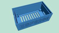
esp8266 box arduino
...esp8266 box arduino
3dexport
box for esp8266 module with wire hole. inside dimensions: 49x26 mm. height 15 mm.
3d_export
$60
Arduino Uno Rev3 Microcontroller 3D Model
...mega328p circuit board spark cable wire 5v 74v 9v 111v
arduino uno rev3 microcontroller 3d model danielgarnier4403 97237 3dexport
3d_export
free

arduino rover kit
...no!!! materials: no!!! rigged: no animated: no uv mapped: no it is not an exact copy of the original! not subject to 3d printing!
3d_ocean
$7
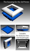
The housing for the 3d Printer
...the housing for the 3d printer 3docean arduino device housing stl the housing consists of two portions:...
3d_export
$5

arm 4 axis
...uno -4 servo motor 180° -3 joystick (x,y) for arduino -mdf wood -some wires -cnc laser cut...
3d_export
$5

solar tracker
...machine for the frame . list of material : -arduino uno -2 step motor with driver -4 ldr sensor...
Driving
turbosquid
$90
Drive
...turbosquid
royalty free 3d model drive for download as blend on turbosquid: 3d models for games, architecture, videos. (1654393)
3d_export
$10

cycloidal drive
...cycloidal drive
3dexport
cycloidal drive
3d_ocean
$5
Flash Drive
...h drive included : – materials – scene ( lighs / room ) – .c4d + .obj for any questions please feel free to contact me thank you.
3d_ocean
$5

Usb drive
...s shaders and a lighting setup. it also has a small animation of it going in and out. i saved it out as both a .blend file and...
3d_ocean
$5

Pen Drive
...est computer drive game model good low poly new pen pen drive textured unwrapped uv very low poly
a very beautiful low poly model
3d_ocean
$10

External hard drive
... is a detailed model of a trekstor external hard drive. you can easily modify the label on the top. simply edit the text objects.
turbosquid
$60

Star Drive
...squid
royalty free 3d model star drive for download as blend on turbosquid: 3d models for games, architecture, videos. (1254314)
turbosquid
$50

Star Drive
...squid
royalty free 3d model star drive for download as blend on turbosquid: 3d models for games, architecture, videos. (1263524)
turbosquid
$45
Star Drive
...squid
royalty free 3d model star drive for download as blend on turbosquid: 3d models for games, architecture, videos. (1287060)
turbosquid
$40
Star Drive
...squid
royalty free 3d model star drive for download as blend on turbosquid: 3d models for games, architecture, videos. (1261902)