Thingiverse
Dragon PSU by aaronroma
by Thingiverse
Last crawled date: 3 years, 1 month ago
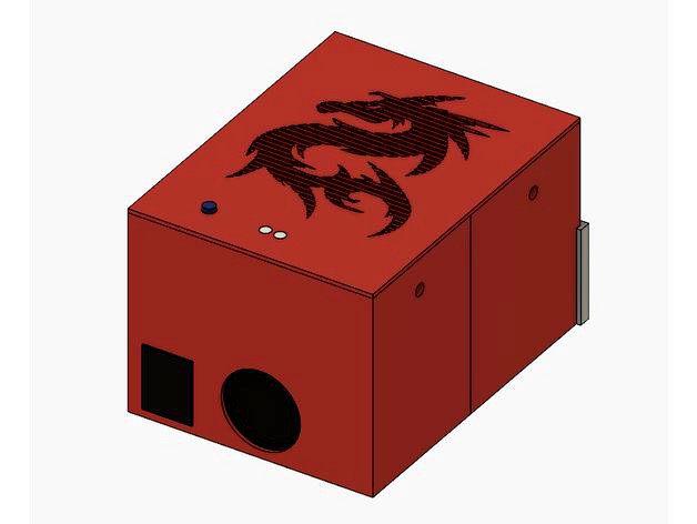
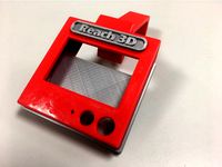
The Dragon PSU is an upgraded power supply I created for my Reach3D printer (http://reach3dprinters.com/). However there's nothing printer specific about this PSU, and it can be used with most 3D printers, if this fits your needs.
I was trying to accomplish a few things by upgrading my power supply. Make more amperage available to the printer. Be able to more quickly heat the bed, and to higher temperatures, without overloading the RAMPS board. And to utilize features of an ATX style PSU to remotely control printer power.
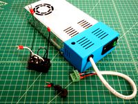
This PSU is designed around some specific hardware components. You will either need to use these same components, or take my ideas and redesign them to fit other components. I've also designed mine with a quick disconnect plug to be able to easily disconnect the PSU and all related wiring from the printer for easier transport. This is optional, of course.
Here's a list of components and hardware that are needed:
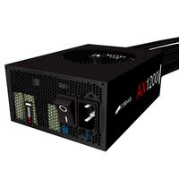
Mini-ITX Power Supplyhttps://www.amazon.com/gp/product/B01M6V8O8T/
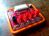
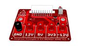
ATX Breakout Board:https://www.amazon.com/gp/product/B01NBU2C64/
MOSFEThttps://www.amazon.com/gp/product/B01HEQVQAK/
Screws / Bolts / Nuts
4 x M3-8mm Socket Head (for fastening lid to case)
4 x M3 Nuts (for fastening lid to case)
9 x #4 Wood Screws (for fastening breakout board, MOFSET, and vent cover)
16 gauge wire (for higher currents)
20/24 gauge wire (for lower currents)
Variety of heat shrink sizes
Variety of your favorite wire loom
Optional Disconnect Plug
16 x M3-20mm Socket Heat
16 x M3 Nuts
Bullet Disconnects (Note, below link is for 22-18 gauge. I actually used 16-14 gauge disconnects, however I couldn't find an online listing for the that size. I had picked them up at my local Lowes store.)https://www.lowes.com/pd/Utilitech-12-Count-Bullet-Wire-Connectors/999953098
Micro USB DYI Connector (for supplying power to Raspberry Pi)https://www.adafruit.com/product/1390
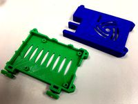
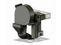
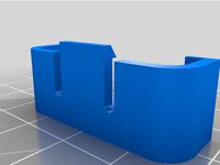
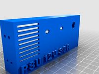
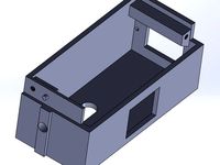
The PSU case itself requires the "Case Front", "Case Back", "Top Cover", "Vent Cover", and "Power Button" files. The "Light Tube" file is optional. The ATX breakout board has two status LEDs. You can see these LEDs through the holes in the lid, or you can print two of these light tubes in a transparent material to bring this light up to the top of the case. The power button and the guide it slides into may require some light sanding for smooth movement. The wiring harness will come out of the PSU, and loop back into the hollow cavity in the side of the case. It then comes up the hole into the upper cavity, where it will plug into the ATX breakout board. Once the two case halves are slid onto the PSU, you'll use the wood screws to mount the breakout board and MOSFET into the upper cavity of the case. The assembly of the case should be fairly straight forward. Reference the exploded drawing of the case that is attached.
The optional disconnect plug consists of 6 parts, Male - Top, Bottom, and Mid, and Female - Top, Bottom, and Mid. The plug is the most difficult and time consuming part of this setup. For the larger 16 gauge wires, I crimped the bullet disconnects onto the wire. For the smaller gauge wire, I actually soldered the wires in. On he male side, you can go through the opening at the base of the metal protrusion to solder the wire. On the female side, I had to trip a bit of the plastic away to get access to the metal to solder to. The printed parts were designed to fit the specific bullet disconnects I used, and may or may not work with others. I designed the parts to hold the printed disconnects in place with pressure. You can optionally glue them in place, but I wanted to ability to change things around if needed, without re-doing the wire ends.
About the wiring. While this can be accomplished without the breakout board by cutting of the end of the wiring harness and directly wiring to the harness, I opted to for the board for a few reasons. One, it keeps me from voiding the warrantee of the PSU, if I had any initial issues with it. Two, helps easily identify where to wire the different components. Three, it provides a physical power button for the PSU. I've attached a simple diagram to help explain the wiring. I'll cover the important notes here:
Inside the PSU case, wire a pair of larger gauge wires between the "DC In" on the MOSFET and a +12V and Common on the ATX board.
Wire a pair of larger gauge wires between another +12V and a Common on the ATX board, to the power input of the RAMPS board.
Wire a pair of larger gauge wires from the "Hot Bed" terminals of the MOFSET to the power wires of the heated bed.
Use a pair of smaller gauge wires between the D9 terminals on the RAMPS board, and the white connector on the MOFSET.
Optional, for PS Control. If you wish to remotely control the PSU, particular handy if using OctoPrint, you'll need a few additional steps:
Wire a smaller gauge wire from the "PS_ON" terminal of the ATX board to the "PS-ON" PIN of the RAMPS board.
If you wish to power a Raspberry PI from the PSU, wire a smaller gauge wire from the "+5VSB" terminal of the ATX board to the 5V terminal of the USB connector. The common terminal of the USB can be wired to a shared common at the RAMPS side.
Firmware changes for PS control:
The Marlin firmware will need to be updated if you wish to control the power supply. There are two lines to change in the configuration.h file. Find the line "define POWER_SUPPLY", uncomment the line, and change the value to a "1", like this: "define POWER_SUPPLY 1". Also, you may want to uncomment the line "define PS_DEFAULT_OFF". This keeps the Mega board from automatically powering the PSU up if it's power flickers, such as a power outage. It keeps the PSU off, until you specifically turn it on.
You can now send the M80 and M81 gcodes to power the PSU On and Off, respectively. Here's how I use this in my setup. Since the Raspberry Pi is connected the 5V standby power of the PS, the RPi remains powered on, and since it's connected via USB to the Mega board, it remains powered up as well. However there is no 12V power supplied the RAMPS board, so the remainder of the printer components are powered down. I can connect to my OctoPrint setup with a web browser, and using a custom button, issue the M80 or M81 commands to power on or power off the printer.
Edit 1/18/2018: There was previously an error on the wiring diagram. I had mistakenly indicated the control wires from the Mofset should be connected to the D9 terminal on the RAMPS board. This has been corrected to the D8 terminal.
I was trying to accomplish a few things by upgrading my power supply. Make more amperage available to the printer. Be able to more quickly heat the bed, and to higher temperatures, without overloading the RAMPS board. And to utilize features of an ATX style PSU to remotely control printer power.
This PSU is designed around some specific hardware components. You will either need to use these same components, or take my ideas and redesign them to fit other components. I've also designed mine with a quick disconnect plug to be able to easily disconnect the PSU and all related wiring from the printer for easier transport. This is optional, of course.
Here's a list of components and hardware that are needed:
Mini-ITX Power Supplyhttps://www.amazon.com/gp/product/B01M6V8O8T/
ATX Breakout Board:https://www.amazon.com/gp/product/B01NBU2C64/
MOSFEThttps://www.amazon.com/gp/product/B01HEQVQAK/
Screws / Bolts / Nuts
4 x M3-8mm Socket Head (for fastening lid to case)
4 x M3 Nuts (for fastening lid to case)
9 x #4 Wood Screws (for fastening breakout board, MOFSET, and vent cover)
16 gauge wire (for higher currents)
20/24 gauge wire (for lower currents)
Variety of heat shrink sizes
Variety of your favorite wire loom
Optional Disconnect Plug
16 x M3-20mm Socket Heat
16 x M3 Nuts
Bullet Disconnects (Note, below link is for 22-18 gauge. I actually used 16-14 gauge disconnects, however I couldn't find an online listing for the that size. I had picked them up at my local Lowes store.)https://www.lowes.com/pd/Utilitech-12-Count-Bullet-Wire-Connectors/999953098
Micro USB DYI Connector (for supplying power to Raspberry Pi)https://www.adafruit.com/product/1390
The PSU case itself requires the "Case Front", "Case Back", "Top Cover", "Vent Cover", and "Power Button" files. The "Light Tube" file is optional. The ATX breakout board has two status LEDs. You can see these LEDs through the holes in the lid, or you can print two of these light tubes in a transparent material to bring this light up to the top of the case. The power button and the guide it slides into may require some light sanding for smooth movement. The wiring harness will come out of the PSU, and loop back into the hollow cavity in the side of the case. It then comes up the hole into the upper cavity, where it will plug into the ATX breakout board. Once the two case halves are slid onto the PSU, you'll use the wood screws to mount the breakout board and MOSFET into the upper cavity of the case. The assembly of the case should be fairly straight forward. Reference the exploded drawing of the case that is attached.
The optional disconnect plug consists of 6 parts, Male - Top, Bottom, and Mid, and Female - Top, Bottom, and Mid. The plug is the most difficult and time consuming part of this setup. For the larger 16 gauge wires, I crimped the bullet disconnects onto the wire. For the smaller gauge wire, I actually soldered the wires in. On he male side, you can go through the opening at the base of the metal protrusion to solder the wire. On the female side, I had to trip a bit of the plastic away to get access to the metal to solder to. The printed parts were designed to fit the specific bullet disconnects I used, and may or may not work with others. I designed the parts to hold the printed disconnects in place with pressure. You can optionally glue them in place, but I wanted to ability to change things around if needed, without re-doing the wire ends.
About the wiring. While this can be accomplished without the breakout board by cutting of the end of the wiring harness and directly wiring to the harness, I opted to for the board for a few reasons. One, it keeps me from voiding the warrantee of the PSU, if I had any initial issues with it. Two, helps easily identify where to wire the different components. Three, it provides a physical power button for the PSU. I've attached a simple diagram to help explain the wiring. I'll cover the important notes here:
Inside the PSU case, wire a pair of larger gauge wires between the "DC In" on the MOSFET and a +12V and Common on the ATX board.
Wire a pair of larger gauge wires between another +12V and a Common on the ATX board, to the power input of the RAMPS board.
Wire a pair of larger gauge wires from the "Hot Bed" terminals of the MOFSET to the power wires of the heated bed.
Use a pair of smaller gauge wires between the D9 terminals on the RAMPS board, and the white connector on the MOFSET.
Optional, for PS Control. If you wish to remotely control the PSU, particular handy if using OctoPrint, you'll need a few additional steps:
Wire a smaller gauge wire from the "PS_ON" terminal of the ATX board to the "PS-ON" PIN of the RAMPS board.
If you wish to power a Raspberry PI from the PSU, wire a smaller gauge wire from the "+5VSB" terminal of the ATX board to the 5V terminal of the USB connector. The common terminal of the USB can be wired to a shared common at the RAMPS side.
Firmware changes for PS control:
The Marlin firmware will need to be updated if you wish to control the power supply. There are two lines to change in the configuration.h file. Find the line "define POWER_SUPPLY", uncomment the line, and change the value to a "1", like this: "define POWER_SUPPLY 1". Also, you may want to uncomment the line "define PS_DEFAULT_OFF". This keeps the Mega board from automatically powering the PSU up if it's power flickers, such as a power outage. It keeps the PSU off, until you specifically turn it on.
You can now send the M80 and M81 gcodes to power the PSU On and Off, respectively. Here's how I use this in my setup. Since the Raspberry Pi is connected the 5V standby power of the PS, the RPi remains powered on, and since it's connected via USB to the Mega board, it remains powered up as well. However there is no 12V power supplied the RAMPS board, so the remainder of the printer components are powered down. I can connect to my OctoPrint setup with a web browser, and using a custom button, issue the M80 or M81 commands to power on or power off the printer.
Edit 1/18/2018: There was previously an error on the wiring diagram. I had mistakenly indicated the control wires from the Mofset should be connected to the D9 terminal on the RAMPS board. This has been corrected to the D8 terminal.
Similar models
thingiverse
free

3D Printer Electronics Enclosure by SkyRider
...;s controller components would be in this box. the power supply is a 450w, but you can put any standard atx type supply in here.
thingiverse
free

Base for benchtop power - ATX breakout board by Gear206
...ll my beautiful .scad-files can be found on my github page
cover and a bracket to mount the whole thing to the psu are to come...
thingiverse
free

ATX Breakout Board V1.1 Power Button by davethegeek
...breakout board that i use with my atx power supply so i designed one. fits perfectly on the seeedstudio - atx breakout board v1.1
thingiverse
free

ATX Breakout Board Bench Power Supply Case by phenoptix
...case but we thought we'd mess around with the design a little and produce our own. here it is!
available to buy at phenoptix.
thingiverse
free

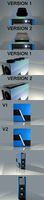
ATX PSU Case with Powerpole connectors by tjko
...pole connector(s), first version has slightly oversized slot for the powerpole connectors while "v2" is very tight fit.
thingiverse
free

Ramps 1.4 housing ATX backplate by Sue3DDesigns
...
a mod for ramps 1.4 housing with 80mm fan and built-in lcd controller 12864 by bernd h. http://www.thingiverse.com/thing:1694188
thingiverse
free
ATX Dangerous Prototypes Power Supply Base by nhmongeon3
.../www.seeedstudio.com/atx-breakout-board-bench-power-supply-p-1222.html?cpath=155
there are other suppliers too.
i used m3 screws
3dwarehouse
free
ATX Breakout Board v1.1
...ts to screw terminals, each protected by a 1.25 amp resettable polyfuse. #atx #breakout_board #dangerous #electronics #prototypes
thingiverse
free

ATX Power Supply Case RAMPS MEGA by Kameleonic
...h corner braces (supplied) and allen head self tapping screws and a bit or brush-on super glue.
need any help? give me a message.
thingiverse
free
Power Supply Cover by thehans
...ply terminals.
works great in conjunction with my psu bracket for 2020 aluminum extrusionhttp://www.thingiverse.com/thing:1091724
Aaronroma
thingiverse
free

Poke Ball by aaronroma
...cutout on the bottom half of the ball. glue the button to this round face.
magnets:https://www.amazon.com/gp/product/b078bggyh8/
thingiverse
free
V-Slot Snap Cover by aaronroma
...ating my printer's spool holder and a mount point for a lcd case i've desinged: https://www.thingiverse.com/thing:2067529
thingiverse
free
OctoPi Case V-Slot Mount by aaronroma
...t, print two of the m3 t-nuts. you will then need 2 m3 nuts to press fit into the t-nuts. you will also need 2 m3 x 6mm bolts.
thingiverse
free

Fire 7 Tablet Stand by aaronroma
... snaps onto the top of the arm. (the "full assembly" file to print... just demonstrate how it all assembles together.)
thingiverse
free

10 Device Charging Station by aaronroma
...s that slide into a corresponding slot. add some glue to the tabs and inside surfaces to permanently attach the halves together.
thingiverse
free

Fire 7 Tablet Case by aaronroma
...l handle. (the split on as a peg which slides into a slot on it's mate. this peg will probably need support when printing.)
thingiverse
free
Reach3D BLTouch + Part Cooling Fan Mount by aaronroma
...od measurement of the z-offset and modify your firmware accordingly.
my offsets are currently set at x: 16, y: -29, and z: -0.95.
thingiverse
free
Case for RAMPS Full Graphic Smart LCD (OpenBuilds V-Slot Mounts) by aaronroma
... for a part cooling solution i'm working on. if you don't want these additional features, use the "a" version.
thingiverse
free
Wyze Sensor Contact Mount
...wyze sensor contact mount thingiverse original thing by aaronroma is a loose fit on my printer, perfect none-the-less....
Psu
3d_ocean
$17
Computer Case
...3docean atx case computer corsair full game gaming pc psu full tower-like computer case model with 113946...
cg_studio
$9
Power Supply Unit PSU3d model
...d .fbx .lwo .ma .max .obj .xsi - power supply unit psu 3d model, royalty free license available, instant download after purchase.
thingiverse
free
PSU cover for 12v 30A PSU by Salti
...
cover for the "dangerous" end of a standard led psu
230v input, 2 x 12v outputs
supports psu width 11cm and height 5cm
thingiverse
free

psu holder by sta8atos
...psu holder by sta8atos
thingiverse
psu holder
thingiverse
free
psu stamp by astorck
...psu stamp by astorck
thingiverse
psu stamp
thingiverse
free

PSU Cover by Shojo
...psu cover by shojo
thingiverse
psu cover
thingiverse
free
PSU cover by chroja
...psu cover by chroja
thingiverse
psu cover
thingiverse
free

PSU Cover for 9,9 cm PSU Anet A8 by Wolverine_DH
...a8 by wolverine_dh
thingiverse
psu cover for 9.9sm psu optimal high for anet a8 screw holes, more side holes for diffrend psus.
thingiverse
free

Anet A8 PSU Fan (2017 PSU)
...coarse threaded fan screws. additionally 2 x m3x8mm machine screws needed to attach fan mount to psu. do not use long than 8mm.
thingiverse
free

SFX PSU to ATX PSU adapter by Kanashii
... atx format adapter so i made my own adapter. better use hard plastic to stick psu to pc's case without breaking the adapter.
Dragon
3d_export
$15

dragon
...dragon
3dexport
dragon
3d_export
$15
dragon
...dragon
3dexport
dragon
3d_export
$5

dragon
...dragon
3dexport
dragon figurine
3d_export
$6

dragon
...dragon
3dexport
cool dragon for decoration
3d_export
$20

dragon
...dragon
3dexport
glass dragon made in blender.
3d_export
$8
dragon
...dragon
3dexport
3d model of the dragon (sculpting)
3d_export
$5

dragon
...dragon
3dexport
dragon 3d model printing
3d_export
$5
dragon
...dragon
3dexport
black dragon with model+render
archibase_planet
free
Dragon
...dragon
archibase planet
toy dragon
dragon n170508 - 3d model (*.gsm+*.3ds) for interior 3d visualization.
archibase_planet
free
Dragon
...dragon
archibase planet
sculpture dragon statue
dragon 1- 3d model (*.3ds) for interior 3d visualization.