Thingiverse
Dr Boo's Parameterised FSR Groove Effector for Delta Printers V3 by DrBoo
by Thingiverse
Last crawled date: 3 years, 1 month ago
27/Nov
VERSION 3
increased passage size for FSR tails. Printed and tested that they fit. Also tested FSR operation in assembled mechanism; it works!
added nut slots for rod connections. Each rod now has its own screw and nut, although there is still the option to use a single large screw if you wish (for each pair).
clamp and plunger now reduced in size, with the top of the E3D/jhead now inserted into the upper plate of the plunger. Plunger is now effectively flush with base of the effector, allowing a standard fan mount to be used on E3D.
17/Nov - This is going to need a bit of a re-think for attaching fan mounts, as they will need to be stationary with relationship to the J-head. Either mounts need to come off the top of the plunger, or the bottom. Probably the bottom...
16/Nov - I have added a WIP SCAD file called BooDeltaUpsideFSR which moves the FSR to the top (undersurface) of the plunger, and places a sloping channel for the FSR tails to exit inwards and up through the plunger, exiting around the pushfit. The reason for this change is that this allows the wiring of the FSR to be tight; the FSR now move with the plunger, which seems to make more sense. I haven't printed this one yet. Also I've been working at reducing the width of the arm connectors, so I'm not sure if the clearance is there for full movement. I may go for one bolt per arm... watch this space....
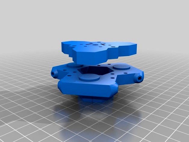
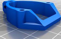
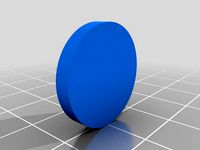
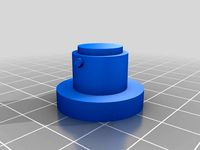
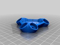
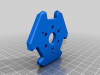
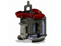
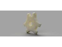
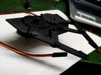
This is an effector/print head assembly with three embedded force-sensitive resistors (FSRs) set into an effector, with spring-loaded 'plunger' to enable z-depth testing using the hothead. It's gone through a few iterations now, and I don't anticipate major changes.
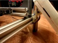
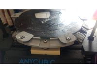
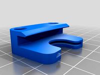
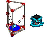
I have successfully printed this, as shown in the pictures, and the head-suspension spring mechanism works well. I'm still building the printer it's to be used on, so actual performance is unknown. I will say, however, that the print head is embedded very firmly into its mount and doesn't shift at all relative to its mount. Also, the 'plunger' is firmly held in place and it's only movement is the up/down axis when pressed on a firm surface. It works exactly as I expected. The mount clamps can be printed separately in ABS if required, as they are screwed on to the plunger.
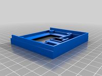
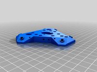
The other bits and pieces are shown in one of the pictures. You need 3x 3mm diameter long screws (say, 44mm), 3x springs (I sacrificed 3 ballpoint pens for these), 3 x 3mm washers, 3x 3mm nuts. The black screws are M3, 25mm the longest I could find locally. They're almost perfect, and the nuts beside them were not needed. There was no drilling required; fresh off the printer I just screwed it all together. The screws simply screw in to the holes with a screwdriver and make their own threads. The hole fit is excellent.
Per the earlier comments, it may be true that a FSR should not be "always on" as it reduces lifespan. However, I don't know that for sure and this is a more elegant design than the alternatives I can think of. In any case, FSR embedded below print beds are also "always on" so clearly it's a reasonable thing to do.
If you have previously downloaded this, I suggest another download and grab the latest version because there have been some minor size and position changes of stuff.
I've recenlty (2/Nov/2014) updated the files with minor changes to hole sizes and placements. Specifically, the 'unused' holes are now positioned so that they have good clearance from everything, and the nut traps are correctly sized and flush with the effector base, so mounting anything underneath the effector won't have any obstacles.
VERSION 3
increased passage size for FSR tails. Printed and tested that they fit. Also tested FSR operation in assembled mechanism; it works!
added nut slots for rod connections. Each rod now has its own screw and nut, although there is still the option to use a single large screw if you wish (for each pair).
clamp and plunger now reduced in size, with the top of the E3D/jhead now inserted into the upper plate of the plunger. Plunger is now effectively flush with base of the effector, allowing a standard fan mount to be used on E3D.
17/Nov - This is going to need a bit of a re-think for attaching fan mounts, as they will need to be stationary with relationship to the J-head. Either mounts need to come off the top of the plunger, or the bottom. Probably the bottom...
16/Nov - I have added a WIP SCAD file called BooDeltaUpsideFSR which moves the FSR to the top (undersurface) of the plunger, and places a sloping channel for the FSR tails to exit inwards and up through the plunger, exiting around the pushfit. The reason for this change is that this allows the wiring of the FSR to be tight; the FSR now move with the plunger, which seems to make more sense. I haven't printed this one yet. Also I've been working at reducing the width of the arm connectors, so I'm not sure if the clearance is there for full movement. I may go for one bolt per arm... watch this space....
This is an effector/print head assembly with three embedded force-sensitive resistors (FSRs) set into an effector, with spring-loaded 'plunger' to enable z-depth testing using the hothead. It's gone through a few iterations now, and I don't anticipate major changes.
I have successfully printed this, as shown in the pictures, and the head-suspension spring mechanism works well. I'm still building the printer it's to be used on, so actual performance is unknown. I will say, however, that the print head is embedded very firmly into its mount and doesn't shift at all relative to its mount. Also, the 'plunger' is firmly held in place and it's only movement is the up/down axis when pressed on a firm surface. It works exactly as I expected. The mount clamps can be printed separately in ABS if required, as they are screwed on to the plunger.
The other bits and pieces are shown in one of the pictures. You need 3x 3mm diameter long screws (say, 44mm), 3x springs (I sacrificed 3 ballpoint pens for these), 3 x 3mm washers, 3x 3mm nuts. The black screws are M3, 25mm the longest I could find locally. They're almost perfect, and the nuts beside them were not needed. There was no drilling required; fresh off the printer I just screwed it all together. The screws simply screw in to the holes with a screwdriver and make their own threads. The hole fit is excellent.
Per the earlier comments, it may be true that a FSR should not be "always on" as it reduces lifespan. However, I don't know that for sure and this is a more elegant design than the alternatives I can think of. In any case, FSR embedded below print beds are also "always on" so clearly it's a reasonable thing to do.
If you have previously downloaded this, I suggest another download and grab the latest version because there have been some minor size and position changes of stuff.
I've recenlty (2/Nov/2014) updated the files with minor changes to hole sizes and placements. Specifically, the 'unused' holes are now positioned so that they have good clearance from everything, and the nut traps are correctly sized and flush with the effector base, so mounting anything underneath the effector won't have any obstacles.
Similar models
thingiverse
free

Raspberry Pi ExoSkeleton Minimalistic Bumper by soundsk
...he hole and tapping it until the support breaks, or run a 3mm drill bit through the hole.
i made this mostly to learn openscad.
thingiverse
free
2020 single rail mount adapter for Pablo's RepRapDiscount LCD case by mukha521
...s with a big head, 1x m5 nut and 2x of those weird nuts for t-slot). also changed hole diameters for m3 screws with a big head...
thingiverse
free
LCR-T4 ESR Meter Case with M3 mounting holes
...threads when you screw them in.
that is all i changed
i included the bottom stl for convenience only, i did not change it at all.
thingiverse
free

Gear Bearing with mounting plates by PaddyCube
...39;t drop a nut inside to screw something on it. i changed the central hole, so you can now drop a nut and screw something on it.
thingiverse
free
Right-handed Fanatec Clubsport Shifter Mount for Playseat Challenge by CarbonBasedLifeform
...-20 bolts/machine screws
4x - m6x~18mm bolts/machine screws
you'l need 1x of the large parts, and 3x of the rectangular pins.
thingiverse
free

FSR Mount Flex Pad by mamenama
...e mine do) and you can't use the silicone pads provided in the kit.
simply print three of them and pop them into your mounts.
thingiverse
free

Small Easy Lads
...ht direction
nov 18 hold head now doesn't have a hole at the back of his head.
nov 25 added wire boye. good luck printing him
thingiverse
free

Dr Boo's Parameterised FSR Groove Effector for Delta Printers by DrBoo
...oned on the ground in the "print this" part; instead, print the components individually; effector, plunger, and clamps.
thingiverse
free
Berd Air Clamp for Smart Effector by NickSchaf
...e a screw drive extruder, but works well with frame-mounted or flying extruders.
printed on my old i3v as i was building a delta.
thingiverse
free
Anycubic kossel spring leveling system and bed holder by Mangosniper
... now and a more secure base which is connected to printer. i think you only need 3 more m4 nuts and m4x12 mm screws additonally.
Drboo
thingiverse
free

Custom Atari 2600 UnoCart Shell by DrBoo
...custom atari 2600 unocart shell by drboo
thingiverse
customisable shell for the atari 2600 unocart.
thingiverse
free

Dr Boo's Creality Dragon Logo - printable by DrBoo
...oo's creality dragon logo - printable by drboo
thingiverse
simple printable stl for creality printer's dragon head logo
thingiverse
free

DR650 Heated Grip Switch Connector by DrBoo
... switch for custom heated grips. it connects adjacent to the key switch. sorry for the crap openscad coding - quick 'n dirty!
thingiverse
free

Dr Boo's DR650 pivot plug by DrBoo
... use silicone to waterproof the edges. the scad file is included if you want to resize things. should be fairly self-explanatory.
thingiverse
free
Dr Boo's 2020 Alphabet by DrBoo
...to individual letters and then print as required.
no special requirements for printing, other than printing them flat on the bed.
thingiverse
free

Dr Boo's CR-10 Extruder Dial by DrBoo
...wn in the picture, but should work for any 5mm shaft. print it slowly, as there's not a lot of surface area to grip the bed.
thingiverse
free
Dr Boo's Ender-3 Nightshade by DrBoo
...nt due to your layer height, or it is too thin, then scale z (only) in your slicer by (say) 125% to make the whole thing thicker.
thingiverse
free

Dr Boo's Measurement scale for CR-10 railing by DrBoo
... and then print blank insert for above/below the rulers. use your slicer to stretch the blank inserts to the appropriate height.
thingiverse
free

Dr Boo's Mini Kossel Endstop for SS5 microswitch by DrBoo
...nside your 1515 channels passing through this end-stop. of course it can be mounted either way (up or down), as per the original.
thingiverse
free

Dr Boo's Remixed Ender-2 Tray by DrBoo
...2 owners having the same issue.
https://youtu.be/evfuk7hdh6a
the belt tensioners are at https://www.thingiverse.com/thing:2672859
Parameterised
thingiverse
free

Parameterised Watch Strap by phedders
...trap width thickness, buckle and hole size etc.
the scad files have been simplified onto the y axis and commented as well.
enjoy!
thingiverse
free
1.5ml Eppie, Parameterised by cathalgarvey
...res" form of the stl.
this stuff is creative commons, attribution, sharealike.http://creativecommons.org/licenses/by-sa/2.0/
thingiverse
free

Openscad grid creator parameterised by Glyn
...openscad grid creator parameterised by glyn
thingiverse
to make a grid for small cages etc.
thingiverse
free

Cable Clip Parameterised by F5Designs
...er to create allow the clip to clamp down on the cable.
i printed this with 2 and 3 layers for the 2mm thickness for a 15mm pipe.
thingiverse
free

Phone support - landscape. Parameterised. by mgg942
...s parameterised so can readily be adjusted for different sizes and shapes of phones.
edit - forgot to upload scad file, now done.
thingiverse
free
XBone Kinect Parameterised TV Mount by mace3d
...xbone kinect parameterised tv mount by mace3d
thingiverse
customisable tv mount for the xbox one kinect.
thingiverse
free
V-Groove Bearing Pulley (Parameterised) by gineer
...d in the middle.
works great for all your linear actuators for sliding along the corners of an aluminium extrusion for example.
thingiverse
free
Simple Parameterised Clip by majordyson
...ed)
this should work fine with many matrials, but petg has the advantage of a little more springiness, so i would reccomend that.
thingiverse
free
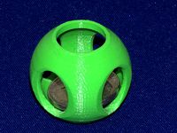
Coin in sphere - parameterised by mgg942
...nscad.
the sizes i've chosen suit an australian 20c coin.
the side portholes are elliptical to make a little easier to print.
thingiverse
free
Parameterised DIY polytunnel seedling planter by sbromwich
...cad in openscad and change to whatever is needed. i suspect arches set to any taller will require arch_thickness to be increased.
Fsr
3dfindit
free

FSR
...fsr
3dfind.it
catalog: festo
3dfindit
free

FSR
...fsr
3dfind.it
catalog: festo
thingiverse
free
FSR Clip by Bron
...fsr clip by bron
thingiverse
block to mount fsr board
3dfindit
free

FSR 2
...fsr 2
3dfind.it
catalog: festo
3dfindit
free
FSR 2
...fsr 2
3dfind.it
catalog: festo
thingiverse
free
Rondelle pour FSR by obor
...rondelle pour fsr by obor
thingiverse
rondelle for fsr
thingiverse
free
FSR case by CrackFox
...ts through holes in the side and is captured. plunger has tabs that will lock it in place with 40 degree ccw turn in the housing.
thingiverse
free

FSR Mount by Gkbeer
...ter screws.
fsr-clip-v2.stl has slotted holes to allow a greater range of adjustment.
inspired by johann's excellent work.
thingiverse
free

FSR Groove Mount by edlep
...to the effector, which protects the nozzle against crashes.
a demo video on my kossel:https://www.youtube.com/watch?v=wzcnmspo-1o
thingiverse
free
T3D v2.0 - FSR Support by E-Mergin
... by e-mergin
thingiverse
fsr support for johnsl fsr kit.
this is dev part for trium3d v2.0, can be used on trium3d v1.0 as well.
Boo
turbosquid
$39

Boo
... available on turbo squid, the world's leading provider of digital 3d models for visualization, films, television, and games.
turbosquid
$50
Kid boo
...id
royalty free 3d model kid boo for download as max and fbx on turbosquid: 3d models for games, architecture, videos. (1676758)
turbosquid
$12

King Boo
... model king boo for download as 3ds, obj, fbx, blend, and dae on turbosquid: 3d models for games, architecture, videos. (1513238)
3ddd
$1
BOO 048 by BLA STATION
... boo
http://www.blastation.com/products/product-families/peekaboo/boo#.vt4cbyhtmkq
turbosquid
$13

Boos Mazinger Z
...
royalty free 3d model boos mazinger z for download as blend on turbosquid: 3d models for games, architecture, videos. (1362964)
turbosquid
free

Super Mario: Boo
...d
free 3d model super mario: boo for download as max and fbx on turbosquid: 3d models for games, architecture, videos. (1316625)
3d_export
$39

boo monsters inc
...boo monsters inc
3dexport
turbosquid
$1

Gamer Chair Big Boos
...alty free 3d model gamer chair big boos for download as blend on turbosquid: 3d models for games, architecture, videos. (1696580)
3ddd
$1

Обои Esta-for-kids коллекция Keek-a-Boo
...обои esta-for-kids коллекция keek-a-boo
3ddd
обои esta-for-kids коллекция keek-a-boo
0,53*10,05см
3ddd
free

Обои Esta-for-kids коллекция Keek-a-Boo
...обои esta-for-kids коллекция keek-a-boo
3ddd
обои esta-for-kids коллекция keek-a-boo
0,53*10,05см
Effector
3d_ocean
$5

Radial Sound Effector
...e spheres will expand with your song. fully customisable, change the color, the size of the spheres or even put in different s...
3d_ocean
$12
3D Customizable Puzzle Set (16x10)
...mograph compatible (you can effect the pieces with mograph effector) - included also a non-mograph version with...
thingiverse
free
Effector by olo2000pm
...effector by olo2000pm
thingiverse
effector
thingiverse
free
CERAMBOT-Effector
...cerambot-effector
thingiverse
cerambot-effector
thingiverse
free

modulize effector by candyasdf
...ulize effector by candyasdf
thingiverse
mount things on effector with m3 screws
effector radius : 25.4mm
rod arm distance : 40mm
thingiverse
free
Delta Effector by zavier
...delta effector by zavier
thingiverse
delta effector with radial fan 50 and bltouch
thingiverse
free
D810 Effector by WhiteTiger13
...d810 effector by whitetiger13
thingiverse
this is d810 effector for d810 without autocalibration, and also cap for it.
thingiverse
free
Effector for Delta Printer
...effector for delta printer
thingiverse
effector for delta printer (3 color)
using diamond hotend
thingiverse
free
Delta effector magnetic by fpassos
...delta effector magnetic by fpassos
thingiverse
effector for e3dv6 hotend. i needed put the spheres (10mm) on the effector.
thingiverse
free
End Effector Gripper
...end effector gripper
thingiverse
end effector gripper
for a robotic arm
uses mg995 servo motor
Dr
design_connected
$16

Dr. Yes
...dr. yes
designconnected
kartell dr. yes computer generated 3d model. designed by starck, philippe.
3ddd
$1
kartell dr. glob
...kartell dr. glob
3ddd
kartell
kartell dr. glob
3d_export
$10
Dr Fate
...dr fate
3dexport
stl for print
turbosquid
$30

Dr. Feelgood
... available on turbo squid, the world's leading provider of digital 3d models for visualization, films, television, and games.
turbosquid
$24

Dr Spark
... available on turbo squid, the world's leading provider of digital 3d models for visualization, films, television, and games.
turbosquid
$1

Dr No Octofuzz
... available on turbo squid, the world's leading provider of digital 3d models for visualization, films, television, and games.
turbosquid
$1
Dr No MadFly
... available on turbo squid, the world's leading provider of digital 3d models for visualization, films, television, and games.
turbosquid
$1

Dr No Kafuzz
... available on turbo squid, the world's leading provider of digital 3d models for visualization, films, television, and games.
cg_studio
$18
Dr Sonderbar3d model
...design chair designer dr sonderbar
.max - dr sonderbar 3d model, royalty free license available, instant download after purchase.
3ddd
$1
agape dr
...agape dr
3ddd
agape , ванна
agape bionic models
Groove
3ddd
$1
Softline / Groove
...softline / groove
3ddd
softline
softline groove
designer: busk+hertzog
2008
design_connected
$13
Groove Tables
...groove tables
designconnected
alain gilles groove tables computer generated 3d model. designed by design is wolf.
turbosquid
$6
Groove Ring
...y free 3d model groove ring for download as 3dm, obj, and stl on turbosquid: 3d models for games, architecture, videos. (1593781)
turbosquid
$16

Bowl Groove
... available on turbo squid, the world's leading provider of digital 3d models for visualization, films, television, and games.
3ddd
$1
Кресло GROOVE
...ey fabric
каркас: нержавеющая сталь/stainless steel
внимание!
в архиве имеются 2011 и 2014 версии файла!
приятного пользования!
3ddd
free

Стул ENNE Groove
...3ddd
enne , groove
современный дизайнерский стул от компании enne.
размеры:
680х490х895
turbosquid
$15
Groove by Milano Bedding
...3d model groove by milano bedding for download as max and fbx on turbosquid: 3d models for games, architecture, videos. (1292946)
turbosquid
$9
Muuto Groove Trivet
...el muuto groove trivet for download as 3ds, max, obj, and fbx on turbosquid: 3d models for games, architecture, videos. (1249093)
turbosquid
$9
Muuto Groove Plate
...del muuto groove plate for download as 3ds, max, obj, and fbx on turbosquid: 3d models for games, architecture, videos. (1248877)
turbosquid
$5

Eleanot Groove Armchair
... available on turbo squid, the world's leading provider of digital 3d models for visualization, films, television, and games.
Delta
design_connected
$16

Delta
...delta
designconnected
lj lamps delta computer generated 3d model. designed by janowski-lenhart, sasha.
design_connected
$16

Delta
...delta
designconnected
arflex international spa delta computer generated 3d model. designed by koivisto, eero.
design_connected
$13
Delta
...delta
designconnected
emu group delta armchairs computer generated 3d model. designed by marin chiaramonte .
3ddd
$1
Delta Light
...delta light
3ddd
delta light , you-turn reo 3033
точечний светильник delta light
3ddd
$1
Blanco / delta
...blanco / delta
3ddd
blanco , мойка
мойка blanco delta со смесителем
3ddd
$1
Delta Light Spot
...delta light spot
3ddd
delta light
светильник фирмы delta light
3ddd
free
Bianchi Delta LVMDLT200100
...i delta lvmdlt200100
3ddd
bianchi delta , смеситель
смеситель bianchi delta lvmdlt200100
design_connected
free
Delta 190
...delta 190
designconnected
free 3d model of delta 190 by zanotta designed by progetti, emaf.
design_connected
$27
Delta 211
...delta 211
designconnected
zanotta delta 211 computer generated 3d model. designed by progetti, emaf.
design_connected
$27
Delta 234
...delta 234
designconnected
zanotta delta 234 computer generated 3d model. designed by progetti, emaf.
V3
3d_export
$5

Poison-v3
...poison-v3
3dexport
poison-v3
3ddd
$1

Curtain v3
...curtain v3
3ddd
полупрозрачная штора v3
turbosquid
free
v3
... available on turbo squid, the world's leading provider of digital 3d models for visualization, films, television, and games.
3d_export
$5
potato v3
...potato v3
3dexport
turbosquid
$69

Skeletor v3
...royalty free 3d model skeletor v3 for download as ztl and obj on turbosquid: 3d models for games, architecture, videos. (1712713)
turbosquid
$49
Zombie v3
...
royalty free 3d model zombie v3 for download as obj and ztl on turbosquid: 3d models for games, architecture, videos. (1342458)
turbosquid
$2

Bitcoin v3
...
royalty free 3d model bitcoin v3 for download as c4d and prj on turbosquid: 3d models for games, architecture, videos. (1182845)
turbosquid
$29
Turret V3
...alty free 3d model turret v3 for download as ma, obj, and fbx on turbosquid: 3d models for games, architecture, videos. (1217498)
turbosquid
$20
Radiators v3
... free 3d model radiators v3 for download as max, max, and obj on turbosquid: 3d models for games, architecture, videos. (1607437)
turbosquid
$10
Wheel V3S
...e 3d model wheel v3s for download as 3ds, obj, fbx, and blend on turbosquid: 3d models for games, architecture, videos. (1344250)
Printers
archibase_planet
free
Printer
...inter
archibase planet
printer laser printer pc equipment
printer n120614 - 3d model (*.gsm+*.3ds) for interior 3d visualization.
archibase_planet
free
Printer
...rchibase planet
laser printer office equipment computer equipment
printer - 3d model (*.gsm+*.3ds) for interior 3d visualization.
turbosquid
$100
Printer
...er
turbosquid
royalty free 3d model printer for download as on turbosquid: 3d models for games, architecture, videos. (1487819)
turbosquid
$3
Printer
...turbosquid
royalty free 3d model printer for download as max on turbosquid: 3d models for games, architecture, videos. (1670230)
turbosquid
$1
printer
...turbosquid
royalty free 3d model printer for download as max on turbosquid: 3d models for games, architecture, videos. (1595546)
turbosquid
$1
printer
...turbosquid
royalty free 3d model printer for download as max on turbosquid: 3d models for games, architecture, videos. (1595105)
turbosquid
$10
Printer
...id
royalty free 3d model printer for download as max and 3dm on turbosquid: 3d models for games, architecture, videos. (1607146)
turbosquid
$7
Printer
...royalty free 3d model printer for download as ma, ma, and obj on turbosquid: 3d models for games, architecture, videos. (1644580)
turbosquid
$30
Printer
... available on turbo squid, the world's leading provider of digital 3d models for visualization, films, television, and games.
turbosquid
$20
Printer
... available on turbo squid, the world's leading provider of digital 3d models for visualization, films, television, and games.