Thingiverse
DIY Rovio Northstar Truetrack Beacon by ScribbleJ
by Thingiverse
Last crawled date: 3 years ago
My fellow Thingicans and Thingocrats; thanks to your help, this project is well under way!
BACKGROUND (robot):
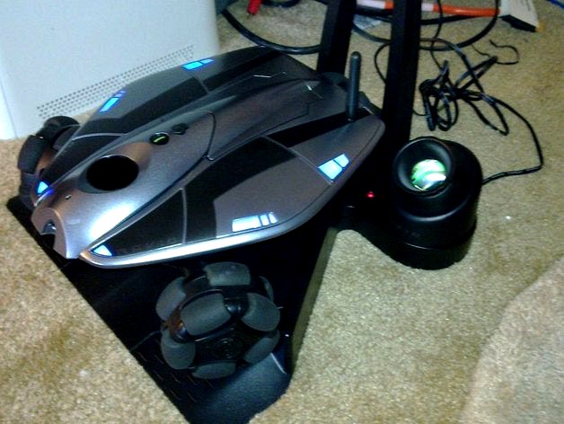
The Wowwee Rovio ( http://www.wowwee.com/en/products/tech/telepresence/rovio/rovio ) is a IP-based Wifi Mobile Webcam, sometimes marketed as a simple telepresence robot. At a price point of about $200, it's money well spent; the system is very well designed both in hardware and software, and you'd have a /very difficult/ time duplicating the ability of this robot for twice the price.
The robot itself is rather hackable, with a well-documented and full-featured web API. The source code to the mainboard was grudgingly released a while back, too, but I've not examined it and I'm told it's useless.
BACKGROUND (tracking):
The robot uses a system from Evolution Robotics called "Northstar" for indoor spatial positioning. The system is very simple at it's most basic concept; the robot has a tiny pinhole camera mounted on it's top. The camera looks at the ceiling for two infrared dots that are projected by a 'Truetrack Beacon.' You could think of it as working very much like a Wiimote.
Evolution Robotics makes sales-level information available here, for an overview of the system: http://www.evolution.com/products/northstar/
The system uses an 'encoding' to allow the Rovio to uniquely identify up to 10 different tracking beacons; the base station it comes with (beacon #0) and up to 9 additional beacon units, which WERE sold separately for a very short time (advertised here: http://www.wowwee.com/en/products/tech/telepresence/rovio/truetrack-room-beacon ). The additional beacon units have a simple switch to select the ID.
MOTIVATION:
Sadly, the Rovio is a dead-end product; the manufacturer (Wowwee) never supported it very well and now has confirmed that they have stopped production and don't intend to ever bring it back.
New tracking beacons cannot be gotten for love or money, and despite the popularity of this product among hackers at one point, there is no data on the actual signaling protocol used by the Northstar system.
Unfortunately, they won't talk to me, and they want /thousands/ for the development kits for the Northstar product, so following legitimate channels is out. In addition, if they /were/ to fork over the details, I'd bet it would put my under an NDA that would prevent publication.
As I don't have /ANY/ tracking beacons (except the one built into the base station), my Rovio is somewhat limited in it's automatic positioning abilities.
WHAT WAS PREVIOUSLY KNOWN:
All the gritty information on the Rovio seems to be concentrated on one site; robocommunity.com.
Here's a thread where some folks dissect the robot and tracking station:http://www.robocommunity.com/forum/thread/14360/Inside-Rovio/
The board we're interested in here is the round one, which is the Northstar beacon projector PCB. There's a lot of great info on it specifically on this thread and the comments:
http://www.robocommunity.com/article/15353/Inside-the-WowWee-Rovio-TrueTrack-Beacon/
Unfortunately, no information on how it actually signals.
WHAT I'VE LEARNED SO FAR:
From looking at the photos in the above thread before I got my robot (I've only had it for one day!) I'd guessed that the signaling protocol was as simple as flashing the two IR lights at different rates. That seems like the simple and obvious method to tell both one light in a beacon from the other, and to tell one set of lights for a beacon from the other.
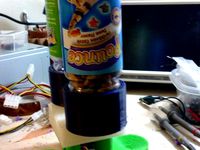
So I opened up my beacon in the base station (instructions in the linked thread), and put a scope on the transistors that drive the LEDs. From my photos, you will see my conjecture seemed to be correct; the LEDs were being blinked at very specific and different rates.
Wiring up a quick circuit with an Arduino to blink a couple of LEDs at the same rate, I took the Rovio and exposed it to my LEDs.
SURE ENOUGH, it immediately recognized it as Tracking Beacon #0, the home station. SUCCESS!
The MAJOR problem is - I only know the signaling speed to reproduce beacon #0, and you can't have two #0s in a network, so what I have so far is only good for people whos base station is destroyed. With the signaling rates here, you can easily build a charging/dock/beacon0 unit from scratch.
If you want the actual rates, they're in my o-scope photo(s). :)
UPDATE (2011-03-18):
I built an automated scanner, which I'll leave to run all night, but it's already produced results! I have a workable ID for NAV BEACON #1. That's one down, 8 to go!
Even if I find them all, though, I could STILL use someone with a scope and real beacon to double-check my work...
I'll be posting some pretty graphs and photos and probably the fuzzing circuit and software shortly.
UPDATE: 2011-03-20
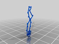
I've been running my scanner for the last day and I'm posting some quick charts as well as the data I've gotten so far. I'm not going to make any claims the data is good, but it has yielded some interesting points!
I also uploaded the latest copies of the scanner software but I'm not sure I've made any noteworthy changes.
UPDATE2: 2011-03-20
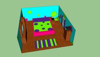
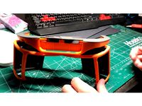
I've built a simple tracking station and placed it in my home, and begun testing. Two things I can report immediately:
1) Getting proper coverage from an LED is not easy, and I'll either have to use an array of LEDs, or a lens, or try the wide angle LEDs I have on order, or some combination of the above.
2) The actual frequencies for room ID #1 reported by botman work better than my 1/3rd frequency in practice.
UPDATES (2011-04-10):
This is mostly a summary of what's in the comments below.
I've decided to move forward using stations based around a pair of transistors (I'll likely use some FETs since we're going to push > 100ma - maybe much > and also because they reduce component count) driving current into a pair of TSAL7200 LEDs (sourced here: http://www.rentron.com/remote_control/IRLED.htm) with the gates switched by a Atmega8, which can be programmed to a given station ID through SPI.
I'll post the circuit the way I have it laid out so far; if anyone can come up with a good single-sided layout for printing and etching at home you'll be doing better than I am; I keep ending up with a few jumper wires required. Keep in mind this circuit hasn't actually been built or tested as posted.
Here's a quick reference of the known station ID frequencies:
3030 and 2010 = Room 0
3150 and 2070 = Room 1
4170 and 3210 = Room 2
4290 and 3330 = Room 3
4410 and 3450 = Room 4
4530 and 3570 = Room 5
4650 and 3690 = Room 6
4770 and 3810 = Room 7
4890 and 3930 = Room 8
5010 and 4050 = Room 9
BACKGROUND (robot):
The Wowwee Rovio ( http://www.wowwee.com/en/products/tech/telepresence/rovio/rovio ) is a IP-based Wifi Mobile Webcam, sometimes marketed as a simple telepresence robot. At a price point of about $200, it's money well spent; the system is very well designed both in hardware and software, and you'd have a /very difficult/ time duplicating the ability of this robot for twice the price.
The robot itself is rather hackable, with a well-documented and full-featured web API. The source code to the mainboard was grudgingly released a while back, too, but I've not examined it and I'm told it's useless.
BACKGROUND (tracking):
The robot uses a system from Evolution Robotics called "Northstar" for indoor spatial positioning. The system is very simple at it's most basic concept; the robot has a tiny pinhole camera mounted on it's top. The camera looks at the ceiling for two infrared dots that are projected by a 'Truetrack Beacon.' You could think of it as working very much like a Wiimote.
Evolution Robotics makes sales-level information available here, for an overview of the system: http://www.evolution.com/products/northstar/
The system uses an 'encoding' to allow the Rovio to uniquely identify up to 10 different tracking beacons; the base station it comes with (beacon #0) and up to 9 additional beacon units, which WERE sold separately for a very short time (advertised here: http://www.wowwee.com/en/products/tech/telepresence/rovio/truetrack-room-beacon ). The additional beacon units have a simple switch to select the ID.
MOTIVATION:
Sadly, the Rovio is a dead-end product; the manufacturer (Wowwee) never supported it very well and now has confirmed that they have stopped production and don't intend to ever bring it back.
New tracking beacons cannot be gotten for love or money, and despite the popularity of this product among hackers at one point, there is no data on the actual signaling protocol used by the Northstar system.
Unfortunately, they won't talk to me, and they want /thousands/ for the development kits for the Northstar product, so following legitimate channels is out. In addition, if they /were/ to fork over the details, I'd bet it would put my under an NDA that would prevent publication.
As I don't have /ANY/ tracking beacons (except the one built into the base station), my Rovio is somewhat limited in it's automatic positioning abilities.
WHAT WAS PREVIOUSLY KNOWN:
All the gritty information on the Rovio seems to be concentrated on one site; robocommunity.com.
Here's a thread where some folks dissect the robot and tracking station:http://www.robocommunity.com/forum/thread/14360/Inside-Rovio/
The board we're interested in here is the round one, which is the Northstar beacon projector PCB. There's a lot of great info on it specifically on this thread and the comments:
http://www.robocommunity.com/article/15353/Inside-the-WowWee-Rovio-TrueTrack-Beacon/
Unfortunately, no information on how it actually signals.
WHAT I'VE LEARNED SO FAR:
From looking at the photos in the above thread before I got my robot (I've only had it for one day!) I'd guessed that the signaling protocol was as simple as flashing the two IR lights at different rates. That seems like the simple and obvious method to tell both one light in a beacon from the other, and to tell one set of lights for a beacon from the other.
So I opened up my beacon in the base station (instructions in the linked thread), and put a scope on the transistors that drive the LEDs. From my photos, you will see my conjecture seemed to be correct; the LEDs were being blinked at very specific and different rates.
Wiring up a quick circuit with an Arduino to blink a couple of LEDs at the same rate, I took the Rovio and exposed it to my LEDs.
SURE ENOUGH, it immediately recognized it as Tracking Beacon #0, the home station. SUCCESS!
The MAJOR problem is - I only know the signaling speed to reproduce beacon #0, and you can't have two #0s in a network, so what I have so far is only good for people whos base station is destroyed. With the signaling rates here, you can easily build a charging/dock/beacon0 unit from scratch.
If you want the actual rates, they're in my o-scope photo(s). :)
UPDATE (2011-03-18):
I built an automated scanner, which I'll leave to run all night, but it's already produced results! I have a workable ID for NAV BEACON #1. That's one down, 8 to go!
Even if I find them all, though, I could STILL use someone with a scope and real beacon to double-check my work...
I'll be posting some pretty graphs and photos and probably the fuzzing circuit and software shortly.
UPDATE: 2011-03-20
I've been running my scanner for the last day and I'm posting some quick charts as well as the data I've gotten so far. I'm not going to make any claims the data is good, but it has yielded some interesting points!
I also uploaded the latest copies of the scanner software but I'm not sure I've made any noteworthy changes.
UPDATE2: 2011-03-20
I've built a simple tracking station and placed it in my home, and begun testing. Two things I can report immediately:
1) Getting proper coverage from an LED is not easy, and I'll either have to use an array of LEDs, or a lens, or try the wide angle LEDs I have on order, or some combination of the above.
2) The actual frequencies for room ID #1 reported by botman work better than my 1/3rd frequency in practice.
UPDATES (2011-04-10):
This is mostly a summary of what's in the comments below.
I've decided to move forward using stations based around a pair of transistors (I'll likely use some FETs since we're going to push > 100ma - maybe much > and also because they reduce component count) driving current into a pair of TSAL7200 LEDs (sourced here: http://www.rentron.com/remote_control/IRLED.htm) with the gates switched by a Atmega8, which can be programmed to a given station ID through SPI.
I'll post the circuit the way I have it laid out so far; if anyone can come up with a good single-sided layout for printing and etching at home you'll be doing better than I am; I keep ending up with a few jumper wires required. Keep in mind this circuit hasn't actually been built or tested as posted.
Here's a quick reference of the known station ID frequencies:
3030 and 2010 = Room 0
3150 and 2070 = Room 1
4170 and 3210 = Room 2
4290 and 3330 = Room 3
4410 and 3450 = Room 4
4530 and 3570 = Room 5
4650 and 3690 = Room 6
4770 and 3810 = Room 7
4890 and 3930 = Room 8
5010 and 4050 = Room 9
Similar models
thingiverse
free
3D TT-Circuit Assen with new post ID's as a keychain by thecreativeexplorer
...d layout of the track, with the new corresponding id numbers.
i added a keychain bow to it, so i can hang it on my track-credits.
3dwarehouse
free

Federal Signal UltraStar
...g #fed #federal #fire #flash #flasher #halogen #led #light #police #revolving #rotating #sig #signal #star #strobe #ultra #whelen
3dwarehouse
free

Austria GP
...so have fun with it! #austria #austria_gp #circuit #gp #gp_circuit_austria #motorbike_track #mrhappysnacky #oostenrijk #racetrack
grabcad
free

Mechanical track (step file!) for SMARS robot by Kevin McAleer
... all.
i hope you'll find this useful for your needs.
all credits goes to kevin mcaleer, the designer of the smars platform.
3dwarehouse
free

Dutch GP
...a circuit extension at the east side of the track near one of the lakes. #circuit #circuitpark #mrhappysnacky #racetrack #raceway
grabcad
free

Robot w/ Tank Track
...y tank tracks, look at my profile or click here -->https://grabcad.com/library/tank-track-2 . i've already published them.
3dwarehouse
free

Vallelunga Circuit
...he vallelunga you want in real. have fun! #circuit #circuit_park #italy #mrhappysnacky #racetrack #racetracks #vallelunga_circuit
grabcad
free

Plastic Line-Bender
...these feel free to ask and i'll post the component list and suppliers.
i also have 600mm, 900mm, 1200mm and 1600mm variants.
3dwarehouse
free

Short City Circuit
...ased on the special stage route 5. i'll post other places because i found that ambient like these are very useful in renders.
3dwarehouse
free
Lauren's room
...this is a model of my room. it's very similar to my actuall...
Rovio
3d_export
$10

angry bird
...fantasy-based video game franchise created by the finnish company rovio ...
thingiverse
free

Rovio Laser Scanner by LucidOne
...hased from ebay and is based on the laser scanner design described here.
http://www.seattlerobotics.org/encoder/200110/vision.htm
blendswap
free

Terence (Angry Birds)
...red of "angry birds" ; ) (character property of: rovio ...
thingiverse
free

Angry Bird by betawolf
...from the game. angry birds is a trademark of rovio entertainment ltd., to which i am not...
thingiverse
free

Omni wheels robot by DFRobot
...omni wheels, driven by three 42 stepper motors. robot rovio was a good example for reference. i disassembled its...
thingiverse
free
Pet Treat Dispenser by ScribbleJ
...the 'webcam' and noise will be provided by a rovio the electronics are arduino-based and can be attached directly...
grabcad
free

ANGRY BIRDS
...is a video game franchise created by finnish company rovio entertainment. the series focuses on multi-colored birds who try...
cg_trader
$5

Angry Birds Pig King | 3D
...an action-based media franchise created by the finnish company rovio entertainment. the series focuses on multi-colored birds that try...
cg_trader
$5

Red Angry Bird | 3D
...an action-based media franchise created by the finnish company rovio entertainment. the series focuses on multi-colored birds that try...
Scribblej
thingiverse
free
ScribbleJ CoreXY Beta by ScribbleJ
...j/corexy-v1https://github.com/scribblej/corexy-v1#corexy-beta
full gallery of development photos here: http://imgur.com/a/donun
thingiverse
free

RAMPS Clip-on Fanmount by ScribbleJ
...ramps clip-on fanmount by scribblej
thingiverse
simple clip-on mount for 40mm cooling fan.
thingiverse
free

Endcap for Pipe or Rod by ScribbleJ
...endcap for pipe or rod by scribblej
thingiverse
simple, customizable endcap for pipe or rod, with optional setscrew.
thingiverse
free

Chapstick Holder by ScribbleJ
...hapstick holder for bicycles!
you might ask "why?" and i couldn't tell you. this item was requested by a friend.
thingiverse
free
Parametric Pen Clip by ScribbleJ
...en clip by scribblej
thingiverse
useful for anything cylindrical. i use it to make clips for my electronic cigarette batteries.
thingiverse
free

Parametric Pipe Mounting Flange by ScribbleJ
...c pipe mounting flange by scribblej
thingiverse
for mounting pipes and rods to flat things -- for example, a shower curtain rod.
thingiverse
free

ScribbleJ's Ring Sizer with Embossed Labels by vandarin
...scribblej's ring sizer with embossed labels by vandarin
thingiverse
added text to the rings.
thingiverse
free

OpenSCAD Bend Module by ScribbleJ
...se
nothing fancy at all, just makes a bend in a cube.
update: as unfancy as it was, a minor bug means i posted a new version.
thingiverse
free
(Yet Another) Printable Quad Frame by ScribbleJ
...(yet another) printable quad frame by scribblej
thingiverse
i'll update this later. maybe.
thingiverse
free

Simple Prusa Spool Mount by ScribbleJ
...ount by scribblej
thingiverse
just a quick and dirty way to mount a spool to your prusa without having to disassemble anything.
Northstar
turbosquid
$15

Retro Computer - Northstar Advantage
...odel retro computer - northstar advantage for download as fbx on turbosquid: 3d models for games, architecture, videos. (1664376)
3d_export
free
NorthStar Battery NSB 100 FT AGM
...northstar battery nsb 100 ft agm
3dexport
3d model of northstar battery nsb 100 ft agm.
3d_export
free

Cadillac LMP-02
...cadillac lmp-02 3dexport 2002 cadillac lmp-02 team cadillac northstar ...
thingiverse
free
Northstar Titanfall_2 by Phototoxin
...toxin
thingiverse
the northstar from tf2.
i will be deconstructing the models into printable pieces but this is just the start.
thingiverse
free
Project Northstar by Indigo4
... indigo4
thingiverse
https://youtu.be/5nizasilzyc
original files for project northstar
all rights belong to the leap motion team
thingiverse
free

Titanfall 2 NORTHSTAR
...titanfall 2 northstar
thingiverse
a titan from titanfall 2.
thingiverse
free
Titanfall Northstar Plasma Railgun by Z-mech
...titanfall northstar plasma railgun by z-mech
thingiverse
this is the main weapon of northstar from titanfall.
thingiverse
free
Titanfall Northstar by Z-mech
...titanfall northstar by z-mech
thingiverse
death from above.
thingiverse
free

Titanfall Northstar ornament by Z-mech
...titanfall northstar ornament by z-mech
thingiverse
death from above
thingiverse
free
Bushnell Northstar Lens Cap by MS3FGX
...bushnell northstar 4.5 inch telescope. inside diameter of cap should be just shy of 50 mm, which will make it a fairly tight fit.
Beacon
3d_export
$5

beacon lowpoly
...beacon lowpoly
3dexport
lowpoly beacon (early version)
turbosquid
$5
beacon
... available on turbo squid, the world's leading provider of digital 3d models for visualization, films, television, and games.
3d_export
$5
Beacon 3D Model
...beacon 3d model
3dexport
beacon lighthouse pharos lowpoly
beacon 3d model kherasan48081 85681 3dexport
archive3d
free
Beacon 3D Model
...use beacon leading light
beacon n240510 - 3d model (*.gsm+*.3ds) for exterior 3d visualization.
turbosquid
$10

Beacon - Lighthouse
...royalty free 3d model beacon - lighthouse for download as max on turbosquid: 3d models for games, architecture, videos. (1190298)
turbosquid
$5
BEACON LIGHT_RAMA
... available on turbo squid, the world's leading provider of digital 3d models for visualization, films, television, and games.
turbosquid
$10

Beacon Writing Desk
... available on turbo squid, the world's leading provider of digital 3d models for visualization, films, television, and games.
3ddd
free

Bark Furniture Beacon Desk Chair
...bark furniture beacon desk chair
3ddd
bark
bark furniture
beacon desk chair
3d_export
free

low poly beacon scene
...low poly beacon scene
3dexport
turbosquid
$15

Avenue Road Beacon Hill Sofa
... road beacon hill sofa for download as max, max, fbx, and obj on turbosquid: 3d models for games, architecture, videos. (1607613)
Diy
3d_export
free
DIY 3D Printer
...diy 3d printer
3dexport
diy 3d printer model
turbosquid
$10

Diy tiered
...l diy tiered for download as max, max, max, max, fbx, and obj on turbosquid: 3d models for games, architecture, videos. (1603709)
turbosquid
$3

Diy Desk to Bench
...odel diy desk to bench for download as 3ds, max, obj, and fbx on turbosquid: 3d models for games, architecture, videos. (1506589)
turbosquid
$2

DIY Moon Light
...model diy moon light for download as obj, fbx, blend, and dae on turbosquid: 3d models for games, architecture, videos. (1501170)
3d_export
$8
DIY CNC Router 3D Model
...diy cnc router 3d model
3dexport
cnc; router; diy; homemade
diy cnc router 3d model maikeru86 58463 3dexport
turbosquid
$5

Diy Kitchen Cabinets
...itchen cabinets for download as 3ds, obj, fbx, blend, and dae on turbosquid: 3d models for games, architecture, videos. (1197373)
3d_export
free

Download free Diying Plant 3D Model
...download free diying plant 3d model
3dexport
diying plant blender
diying plant 3d model visitorsama 98607 3dexport
3ddd
$1
DIY coffee table + decor
... рамка для фото
кофейный столик diy 400х350х600(h) мм. моделился по фото. внимание: материалы - corona.
turbosquid
$3

Diy Wire Lamp Shade
...free 3d model diy wire lamp shade for download as 3ds and fbx on turbosquid: 3d models for games, architecture, videos. (1347605)
cg_studio
$12

DIY MONGOLIAN LAMB STOOLS3d model
... hair soft pile white
.max - diy mongolian lamb stools 3d model, royalty free license available, instant download after purchase.