Thingiverse
DIP-Clip for In-Circuit Programming/Analyzing ICs by enif
by Thingiverse
Last crawled date: 2 years, 12 months ago
In my projects I often use microcontrollers which can be reprogrammed via ISP (in-circuit programming). If there is enough space, I usually intergrate a 6-pin ISP header, so that I can easily reload new firmware if required. However, sometimes, space is at a premium, which means I'll have to do without an ISP header.
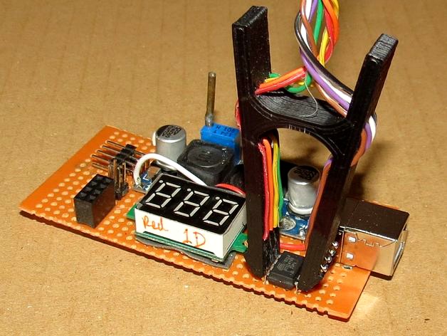
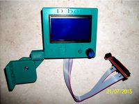
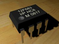
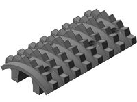
So the aim of this project was to generate a contact clip for in-circuit analyzing and programming of standard DIP ICs with 0.1" pin spacing, which allows me to reprogram microcontrollers and EEPROMs, and also debug my developments by analyzing the pin signals on the ICs directly.
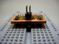
The pin contacts are made from standard pin headers. The bridge in the clip tweezers provides a spring to firmly clamp the contacts to the IC. Small gaps between the pins allow each pin arm to move individually, so that the contact force is spread to all pins evenly. The lead wires are fed from the inner rear of the clip through three holes to the outer front of the clip where they are soldered to the contacts headers.
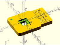
For printing, ABS is preferred in order for the plastic to provide the necessary elasticity. To allow printing despite of the (in printing position horizontal!) gaps between the pin arms, explicit supports are generated (shown red in the OpenScad drawing) which need to be cut away with a razor blade or a narrow knife after printing. As the arms should move freely against each other, sometimes it is necessary to "clean" the gaps with thin sandpaper. The holes for the pin headers and the wires are quite tight, so it may be necessary to cleanly redrill them after printing, for the pin header tips I got the best results with a 0.8mm drill bit.
STL files for the standard 8-, 14-, 16-, 20- and 28-pin narrow DIP ICs as well as for 28- and 40-pin wide DIP ICs are provided. Other sizes can be easily obtained by modifying the fully parametrized SCAD file.
Note that this project was not as easy to accomplish as I initially thought. The approach presented here is the result of several iterations, from first using simple wire loops, the switching to pin headers for the contacts and finally introducing the free swinging pin arms - the latter were definitely the key for getting good contacts on each pin every time...
So the aim of this project was to generate a contact clip for in-circuit analyzing and programming of standard DIP ICs with 0.1" pin spacing, which allows me to reprogram microcontrollers and EEPROMs, and also debug my developments by analyzing the pin signals on the ICs directly.
The pin contacts are made from standard pin headers. The bridge in the clip tweezers provides a spring to firmly clamp the contacts to the IC. Small gaps between the pins allow each pin arm to move individually, so that the contact force is spread to all pins evenly. The lead wires are fed from the inner rear of the clip through three holes to the outer front of the clip where they are soldered to the contacts headers.
For printing, ABS is preferred in order for the plastic to provide the necessary elasticity. To allow printing despite of the (in printing position horizontal!) gaps between the pin arms, explicit supports are generated (shown red in the OpenScad drawing) which need to be cut away with a razor blade or a narrow knife after printing. As the arms should move freely against each other, sometimes it is necessary to "clean" the gaps with thin sandpaper. The holes for the pin headers and the wires are quite tight, so it may be necessary to cleanly redrill them after printing, for the pin header tips I got the best results with a 0.8mm drill bit.
STL files for the standard 8-, 14-, 16-, 20- and 28-pin narrow DIP ICs as well as for 28- and 40-pin wide DIP ICs are provided. Other sizes can be easily obtained by modifying the fully parametrized SCAD file.
Note that this project was not as easy to accomplish as I initially thought. The approach presented here is the result of several iterations, from first using simple wire loops, the switching to pin headers for the contacts and finally introducing the free swinging pin arms - the latter were definitely the key for getting good contacts on each pin every time...
Similar models
thingiverse
free
ATtiny45/85 ISP adaptor. by dmellis
...e breadboard next to the appropriate legs of the microcontroller, and a 6 pin avr isp header that your programmer can connect to.
3dwarehouse
free

2x3 shrouded header
...r
3dwarehouse
header designed for avr's icsp (in-circuit serial programming, or isp) #2x3 #header #icsp #isp #pins #shrouded
3dwarehouse
free

IC, 16 pin, DIP package
...ated circuit in 16 pin dip package. #16 #74xx #chip #circuit #cmos #component #dip #dip16 #electronics #ic #integrated #pin #pins
thingiverse
free

holder for isp header (10 Pins) by weigu
...holder for isp header (10 pins) by weigu
thingiverse
holder to fix an 10 pin isp header to a housing.
print it with support!
thingiverse
free

ISP Header by ThomasVDD
...isp header by thomasvdd
thingiverse
6 pin isp header.
grabcad
free

Integrated Circuit DIP
....54mm pitch distance between each pin, and the distance for each row of pins is 8.5mm, which makes it ideal to be added to a pcb.
thingiverse
free

AVR ISP Programmer
...bay.com/itm/socket-40p-40pin-zif-zip-ic-test-tester-board-socket-good-quality/381374691968?hash=item58cbb3fa80:g:jtkaaoswdn1unle5
thingiverse
free

DIP IC Test Clip by Naturaltangent
...e following versions (all other parameters left at default);
stl
ic_pin_count
ic_width
dip_clip_16.stl
16
8
dip_clip_40.stl
40
14
thingiverse
free
ISP Flasher Adapter for Mega8 Atmel AVR TQFP32 by HenningS
... - it's cheap and simple, but it works!
printed with 0.1mm step, 0.4mm nozzle and 40% infill. no support structure required.
thingiverse
free

Wire Clip by pathfinderzero
... simple wire clip remix that i use to organize wires inside my cr-10 enclosure. i narrowed the gap to keep the wires in the clip.
Enif
3d_sky
free
HYDRA ENIF
...hydra enif
3dsky
poltraona frau
1000x1000
unity_asset_store
$18

Enif Cruiser
...r workflow with the enif cruiser asset from pleiades shipyards. find this & other space options on the unity asset store.
3dbaza
$7

Kompan Enif Game Complex (17747)
...ex (17747)
3dbaza
scene includes: 3d model of the gambling complex kompan enif<br>3dsmax 2016 + corona, textures included.
thingiverse
free

Battery Holder by enif-txoof-webmongersimonsolar2c by SimonSolar2C
...the txoof script which caused a hole underneath.
putting it here so i can make battery holder with his improvement to the markers
thingiverse
free

Reverse battery protection for AA Flexing battery holder by enif
...a dab of glue.
1.6 to 1.8mm thickness works fine. it depends on what material (wire, copper foil, ...) you use for your contacts.
thingiverse
free

Plug for bicycle hub dynamo by enif
...re the inner part is pushed into the outer shell, squeezing the wires for a firm hold. (the last photo shows the original plug.)
thingiverse
free

Simple snap-in ball bearing frame by enif
...imensioned for the standard 608zz type ball bearing, but the scad file can easily be configured for other types of ball bearings.
thingiverse
free

Magnetic Letters & Numbers by enif
... contains the character definitions.
update 2015-10-10: i have now also uploaded the stl files for the lower case characters a-z.
thingiverse
free
Remix of Double Hinged 12864 Full Graphics LCD Frame by enif by FrancescoF
...cd12864 all together, deep enough to fit exp1 and exp2 connectors.
redesigned the support to fit on a v-slot rail 20x20 or 20x40.
thingiverse
free

Eyecaps for Binoculars - fully parametrized by enif
...eed to be flexible when the binoculars are folded for storage, the material of choice for printing the eyecaps is definitely abs.
Analyzing
turbosquid
$50

Computer Dell
...puter for chemistry analyzer for download as ma, obj, and fbx on turbosquid: 3d models for games, architecture, videos. (1334649)
3d_export
$15

Alcohol Breathalyser 3D Model
...halyser blood device machine test screening breath lcd car auto police stop
alcohol breathalyser 3d model kreatura 93186 3dexport
cg_studio
$15

Alcohol Breathalyser3d model
...police stop
.fbx .obj .max .3ds - alcohol breathalyser 3d model, royalty free license available, instant download after purchase.
3d_ocean
$7

Detergent Bottle 900 ml
...th rhinoceros. getting high detail and perfect curves on complex surfaces. surfaces analyzed with diagnostic tools and ‘zebra’...
3d_ocean
$7

Detergent Bottle 750 ml
...th rhinoceros. getting high detail and perfect curves on complex surfaces. surfaces analyzed with diagnostic tools and ‘zebra’...
3d_export
$69
v-eleq electrical control simulation software
...rol circuit. at the same time, it can also demonstrate and analyze various faults in the wiring process through visual simulation
3d_export
$80
us army m1130 command vehicle stryker cv with detailed interior max obj
...g 3d models with superior quality. customized modeling service/format translation/additional tech support available upon request.
3d_export
$20
power cord adhesive tape machine
...anipulator: 0.005 mm, repeated positioning accuracy of manipulator: ≤ ± 0.01 mm, and material change mode: manual material change
3d_export
$74

Best Local solar companies in US
...xpert installers and expert elect ricans. the system has been doing the job to perfection as it was put in one particular yr ago.
3d_export
$7
wire and wire copper axis fpc adhesive tape laser cutting peeling cutting machine - final assembly
... learn a lot. i won't introduce other details here. the above is the whole structure and working principle of this equipment.
Dip
turbosquid
$50
Dip Tank
... available on turbo squid, the world's leading provider of digital 3d models for visualization, films, television, and games.
turbosquid
$35
Dip sink.c4d
... available on turbo squid, the world's leading provider of digital 3d models for visualization, films, television, and games.
turbosquid
free

DIP-16
... available on turbo squid, the world's leading provider of digital 3d models for visualization, films, television, and games.
3ddd
free

Dip 110Prim
...dip 110prim
3ddd
журнальный , круглый
журнальный стол, dip_110prim
turbosquid
$3

Dangerous dip Roadsign
...rous dip roadsign for download as 3ds, obj, fbx, dae, and stl on turbosquid: 3d models for games, architecture, videos. (1493746)
turbosquid
$1
8 pin dip
... available on turbo squid, the world's leading provider of digital 3d models for visualization, films, television, and games.
turbosquid
$20
Freestanding Washbasin Aquamass Dip
... available on turbo squid, the world's leading provider of digital 3d models for visualization, films, television, and games.
turbosquid
$14

Chopstick Dip Salmon Sushi
...ip salmon sushi for download as 3ds, obj, fbx, blend, and dae on turbosquid: 3d models for games, architecture, videos. (1379737)
turbosquid
$14

Chopstick Dip Dory Sushi
... dip dory sushi for download as 3ds, obj, fbx, blend, and dae on turbosquid: 3d models for games, architecture, videos. (1343854)
turbosquid
$12

Chopstick Dip Cylinder Sushi
... cylinder sushi for download as 3ds, obj, fbx, blend, and dae on turbosquid: 3d models for games, architecture, videos. (1379729)
Circuit
turbosquid
free

Circuit Board
...turbosquid
free 3d model circuit board for download as blend on turbosquid: 3d models for games, architecture, videos. (1279126)
turbosquid
$20

CIRCUIT BREAKER
... available on turbo squid, the world's leading provider of digital 3d models for visualization, films, television, and games.
turbosquid
$19
Circuit Breaker
... available on turbo squid, the world's leading provider of digital 3d models for visualization, films, television, and games.
turbosquid
$19
Circuit Breaker
... available on turbo squid, the world's leading provider of digital 3d models for visualization, films, television, and games.
turbosquid
$19

Circuit Breakers
... available on turbo squid, the world's leading provider of digital 3d models for visualization, films, television, and games.
turbosquid
free

Circuit Breaker
... available on turbo squid, the world's leading provider of digital 3d models for visualization, films, television, and games.
3d_export
$65

circuit board
...circuit board
3dexport
simple rendering of the scene file
archive3d
free

Circuit breaker 3D Model
...rcuit breaker schneider electric n240211 - 3d model (*.gsm+*.3ds) for interior 3d visualization.
turbosquid
$35

Short circuit key
...
royalty free 3d model short circuit key for download as 3ds on turbosquid: 3d models for games, architecture, videos. (1187722)
design_connected
free

Circuit 1 Sconce Lamp
...circuit 1 sconce lamp
designconnected
free 3d model of circuit 1 sconce lamp by apparatus
Ics
3d_export
$19

Cartoon Iceberg Ice Cave sea surface Snow Mountain ice ice surface sea ice cone Ice Cave gla
...on iceberg, ice cave, sea surface, snow mountain, ice, ice surface, sea ice cone, ice cave, glacier 2.files include 3dmax fbx obj
3d_export
$19

Cartoon Iceberg Ice Cave sea surface Snow Mountain ice ice surface sea ice cone Ice Cave gla
...on iceberg, ice cave, sea surface, snow mountain, ice, ice surface, sea ice cone, ice cave, glacier 2.files include 3dmax fbx obj
3d_ocean
$2
Ice
...snow texture tile
this is a tile able, hand painted ice texture tile. included is one versions at 512×512 pixels in .tga format.
3d_ocean
$2
Ice Dispenser
...cooler
ice dispenser model in 3ds max. you can see this machine in soft drink shop, super market, hypermarket and some fast food.
3d_export
$5

Ice cream
...ice cream
3dexport
ice crice
3d_export
free
Donut with icing
...donut with icing
3dexport
donut with icing
3d_ocean
$3
ice cubes
...ice cubes
3docean
coke cube ice soda beverage
3d model and shader of ice cubes
3d_export
$12
ice cream
...ice cream
3dexport
ice cream, made in blender
3d_export
free
Ice box
...ice box
3dexport
it is a ice box as shown in the pictures.
3d_ocean
$2

Ice Texture
...al freeze frost frozen frozen water ice icey snow winter
the texture of the ice / ice surface. files included: tga and jpg files.
Programming
3d_export
$65

Ancient programs
...ancient programs
3dexport
simple rendering of the scene file
3d_export
$65

Ancient programs
...ancient programs
3dexport
simple rendering of the scene file
turbosquid
$75

TV SPORT PROGRAM STUDIO
...lty free 3d model tv sport program studio for download as obj on turbosquid: 3d models for games, architecture, videos. (1230966)
turbosquid
$45

SOCIAL MEDIA PROGRAM STUDIO
...free 3d model social media program studio for download as obj on turbosquid: 3d models for games, architecture, videos. (1232365)
turbosquid
$4
Cohesion Program Extendable Dining Table
... cohesion program extendable dining table for download as max on turbosquid: 3d models for games, architecture, videos. (1603910)
3ddd
free
Tonin Casa / Composizione 2 Program Leaves
...tonin casa / composizione 2 program leaves
3ddd
tonin casa
composizione 2 коллекция program leaves(материалы+текстуры)
3d_export
$20

Women Program 015 3D Model
...tertainment display show television advertising art arts architecture design
women program 015 3d model akeryilmaz 96034 3dexport
cg_studio
$15

Tv Chat Program 0203d model
...tl .3ds .obj .max .fbx .dxf .dwg - tv chat program 020 3d model, royalty free license available, instant download after purchase.
cg_studio
$15

Tv Chat Program 0193d model
...tl .3ds .obj .max .fbx .dxf .dwg - tv chat program 019 3d model, royalty free license available, instant download after purchase.
cg_studio
$25

Tv discussion program 0173d model
...s .dae .c4d .obj .max .fbx - tv discussion program 017 3d model, royalty free license available, instant download after purchase.
Clip
archibase_planet
free
Clip
...clip
archibase planet
paper-clip clip office equipment
clip band - 3d model for interior 3d visualization.
3d_export
$5
screw clip
...screw clip
3dexport
screw clip
3d_ocean
$4
Butterfly clip
... a butterfly clip, it comes with a ready to render set for out of the box rendering. obj version and max alones version included.
turbosquid
$2

clip
...
royalty free 3d model clip for download as ma, obj, and fbx on turbosquid: 3d models for games, architecture, videos. (1358622)
turbosquid
$5

Clip
...lty free 3d model clip for download as c4d, 3ds, fbx, and obj on turbosquid: 3d models for games, architecture, videos. (1521355)
turbosquid
$19
Clip
... available on turbo squid, the world's leading provider of digital 3d models for visualization, films, television, and games.
turbosquid
$4
Clips
... available on turbo squid, the world's leading provider of digital 3d models for visualization, films, television, and games.
turbosquid
$3
clip
... available on turbo squid, the world's leading provider of digital 3d models for visualization, films, television, and games.
turbosquid
$2

clips
... available on turbo squid, the world's leading provider of digital 3d models for visualization, films, television, and games.
turbosquid
free

clip
... available on turbo squid, the world's leading provider of digital 3d models for visualization, films, television, and games.