Thingiverse
Deterministic Retraction Calibration by orgemd
by Thingiverse
Last crawled date: 4 years, 7 months ago
Update 3/24/2020:
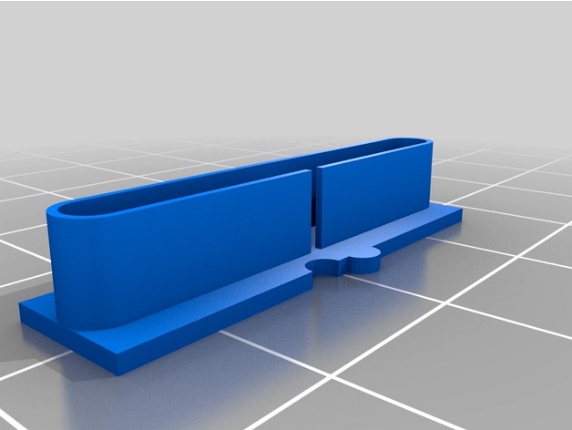
Over time, the version2 of this thing became ineffective. Any iteration is an attempt to control slicer print paths, and the logic that they use changes as they are updated. I found myself needing to run these tests again, so I made an updated version3 that at least works with the slicer I use - Slic3r Prusa Edition (2.2 currently). I had to set detect thin walls for it to work. Once I slice, the visualizer will show all retracts stacked up on the side with the indent, straight line travel across the gap, and reload stacked up on the far side. If you don't see that in your visualizer, tweak slicer settings to try to get it. If you can't get that, it probably isn't worth bothering to print. I think this version should hold up better over time - as long as the right slicer settings are used. There are not a lot of path choices for this version that would make sense other than the desired one. As always, OpenSCAD file is included and you can tweak it if you need something different. I set the width to right around my filament extrusion width. I expect you might need to change that if your print settings are different from mine. If you print wider, then you might not see the vertical fin at all when you slice it. If you print narrower, you might get two passes on each layer instead of one. I have left the previous version2 in case it is still useful to someone, but most users will want to try version3 at this point.
Original:
After building a new printer, I needed to calibrate retraction. I found, however, that current methods provided little help. Every calibration object I found had issues. I eventually decided that I would need to create my own calibration part. Towards that end, I came up with the following list of what I think makes a good retract calibration object:
1) As much as possible, a good retract calibration object should only test retraction. It should be mostly independent of other calibrations, and therefore easy to print. Many retract calibration objects require that printers be well calibrated for numerous other parameters. Some test retraction, but also depend on cooling, overhang, Z registration, extrusion flow rate, and other things. That not only makes the object hard to print, it also makes it difficult to say how well retraction is working. For example, cooling problems might result in pulling strings of molten plastic - that might look like a retraction problem where none exists.
2) It should be clear where retract and reload occurred on the calibration object, and what the travel was between them. Many retract calibration objects visually look like they will provide this, but fail in reality. When the GCODE is visualized, the extrusion path is complex. Retracts do not take place where expected, and travel after retract does not go where one would think. This makes it very hard to tell under what circumstances retraction is working.
3) The retract calibration object should give quantitative results. Many current objects give nothing more than a qualitative result. Although there is an indication that retraction is working to some extent, there is rarely an indication of the limits of that extent.
4) Printing the calibration object should not take much time or filament. Many current objects print much more than needed to evaluate retraction.
5) Ideally, it should be possible to customize the calibration object to better suit specific printer needs.
After a number of failed attempts at designing a good test object, this calibration part is the one I have settled on. For me, it meets all of the above requirements. The print is very easy and forgiving, and gives a clear indication of how retract is working for specific gap sizes. I have already made big improvements using this object, and expect to make more.
The OpenSCAD source is included with parameters to make customization easy should you need different settings from the ones I used in producing the included STL files.