Thingiverse
Da Vinci Duo 2.0 Chimera Edition with 200x200 printbed upgrade by NAK3DDesigns
by Thingiverse
Last crawled date: 3 years ago
Updated 09/29/2018
Added file for new corner cover with integrated chain mount for relocating the x-axis wiring in cable chain.
Updated 09/02/2018
Posted a revised version of the 20mm carriage(Chimera_Carriage_20mm_Rev_2_with_removable_cap.stl) after discovering a few minor problems. Created more room for heatblocks, widened opening for wire feed thru, and cleaned up plug area for better fitment.
Updated 07/25/2018
I've uploaded my latest version of my carriage for the new E3D 20mm Chimera design. The file is named "Chimera_Carriage_v6_20mm_with_removable_cap". It uses a new single bolt design to hold the belt using a heat set to prevent the screw from working loose(an issue with earlier designs when printing ABS and higher temp filaments). You will also need an Aluminium 2GT timing belt clamp like the on in this link https://www.ebay.com/itm/5-x-Pcs-2GT-Timing-Belt-Aluminum-Gear-Durable-Sturdy-Clamp-Mount-Block-Pack/222530321403?hash=item33cfd73bfb%3Ag%3AVlcAAOSwcgNZLuIo&LH_PrefLoc=1&_sacat=0&_nkw=2GT+Timing+Belt+clamp&_from=R40&rt=nc
I hope to have a series of video's filmed in the very near future with step by step instructions for this entire MOD. I'll post the link once I start posting them.
Warning The carriage is designed to work with the old Chimera that is 18mm between the nozzles. I will be releasing an updated version for the new 20mm spaced Chimera as soon as I get a chance to print and test the updated version.
Updated 12/07/2017
Re-loaded the V4 version of the Chassis that I originally posted back on 08/20/2017. Not sure what happened that the old version ended up back on the posting.
UPDATED 09/10/2017
As promised I have added an PDF document with full step by step instructions with pictures. I have also added a basic chain mount if you wish to eliminate the Extruder Circuit board as I have. Good Luck!!!
UPDATED 08/27/2017
Added new pics of the latest design assembled with all wires fed into the molex connector.
UPDATED 08/22/2017
Added a few pics of the assembled printbed support. You'll need to install the front three screws and then use the holes at the back of the two side brackets as a guide to drill out your Z-axis chassis for the remaining two screws.
UPDATED 08/20/2017
Replaced the Version 3 carriage with an updated Version 4. Realized you couldn't get the Molex pluged in for the cable chain mount. Moved it out and up for clearance.
UPDATED 07/23/2017
I've added a revised version of the carriage with the rear oiling points located in an easier to access location. I've also revised the cable holder to allow for a snap in female Molex connector (part #WM2483-ND) and used with matching male connector (part #WM2489-ND) for easier connecting and disconnecting of the print carriage.
I've also added the files for the front support brackets, support brace, and new thermistor bracket for the 200 x 200 print bed kit. The support brace is to help reduce twisting of the z carriage.. I recommend printing these in ABS with 25% infill as there is some heat transfer to the y carriage plate that has softened PLA when printing with the Bed at Higher temps(found out the hard way during prototyping).
I used a RepRap heated print bed.http://www.ebay.com/itm/PCB-Heated-Hot-Bed-MK2B-for-RepRap-3D-Printer-pre-wired-for-12V-SMT-LED-soldered/122063000091?ssPageName=STRK%3AMEBIDX%3AIT&_trksid=p2057872.m2749.l2649
A Prusa I3 universal Y-carriage.http://www.ebay.com/itm/Prusa-i3-Universal-Y-Carriage-Plate-Upgrade-Aluminum-Anodized-for-3D-Printer/121561406955?ssPageName=STRK%3AMEBIDX%3AIT&_trksid=p2057872.m2749.l2649
I did have to modify the carriage by drilling out the 4 corner holes with a 5mm drill bit and taped them to a M6x1 for installing m3 x.5 EZ loks McMaster Carr part # 97120A190.
On the new thermistor bracket there is a breakaway portion. once bolted to the y carriage plate use the hole in the break-away portion as a guide for drilling a 2.5mm hole and tap to M3 x .5 for installation of your rear bed adjustment screw.
All drill bits and taps are also available on McMaster Carr.
Some adhesive backed 3mm think silicone mat.http://www.ebay.com/itm/12-X12-Black-White-Silicone-Rubber-Sheet-Self-Adhesive-High-Temp-Plate-Mat/122242663272?ssPageName=STRK%3AMEBIDX%3AIT&_trksid=p2057872.m2749.l2649
And an E3D Borosilicate 4mm think 214mm x 214mm glass platehttp://e3d-online.com/Mechanical/Print-Surfaces/Borosilicate-Bed-200x200
held down with some 1/8 mirror clips.http://www.ebay.com/itm/CRL-Zinc-Plated-Offset-Mirror-Clip-for-1-8-Glass-Pack-of-100-by-CR-Laurence/191936825710?ssPageName=STRK%3AMEBIDX%3AIT&_trksid=p2057872.m2749.l2649.
I've also uploaded a new Repetier file (Repetier_chimera_200.zip) with the proper settings for the 200 x 200 print bed and smaller drip trays. Just unzip this folder to the same location as your current Repetier folder in ArduinoDUE and then open the Repetier_chimera_200.ino file and re-flash your printer.
I will take more assembly pics and provide more instruction as I install this on my next printer. As this is getting long I may create a step by step instructions document and upload that to make things easier.
Should anyone get to this point before I complete the instruction feel free to message me and I will do my best to help you finish the upgrade.
Update 06/12/2017
I've added the files for revised(narrower) left and right drip trays. After trying for several months to make the 200x200mm print bed work with only one original drip tray I have come to the conclusion that it just won't work nor will it fit between the originals. If you want to stick with your 150-200mm print bed then no need to print these. For the 200x200 upgrade you'll need to print both the left and right drip tray and two of the drip boxes.
There are two versions of the drip trays I had little luck with conventional supports for the hanging tabs so I made a version with a more robust support.
More files and a new firmware update will be loaded shortly as well as a parts list for the upgrade, I'm just making a few final tweaks to the mounting brackets and doing some final testing.
Update 03/28/2017
I've added a bracket for relocating the cleaning tab to allow its use with the new print head.. Admittedly I have made so many changes to the firmware that I have uploaded a zip file of my entire Repetier folder. Changes now include Everything from the previous config file as well as removing all movement to the left drip tray and new "Clean" commands to use the newly located cleaning tab to clean both sides of the extruder. I've also turned off the filament sensors and top cover sensors by default. Thanks to Luc at Git-Hub for helping me remove the code for the left drip tray and in setting up the new "Clean" commands.
Update 03/26/2017
I've added a file Configuration.rtf. This is a copy of my Configuration.h file from my Repetier.ino flash. There are nine changes I made to align the print and they are all highlighted in yellow. You will need to open Arduino and load your Repetier.ino file and make these changes to the Configuration.h tab then re-flash your printer. I'm still working to eliminate the load/unload movement to the left drip tray and will post once I figure out how to default both the left and right to the right drip tray.
Warning this is not for the faint at heart... lol Several wires will need to be cut and soldered..
Thanks to Caj for creating a mock up of the Duo carriage(not much of hers left but it gave a good starting point). I posted two versions of the new carriage one has a Chimera logo I found embossed on the side one does not.. This is the only difference in the two files.
You will also notice there are holes directly over the bearings. If you look closely in my pics I have drilled holes in my bearings and ground small journals with spherical diamond dremel bits to allow for easy oiling. I've been using this on my 1.0 for the last 3 months and it seems to work great.
Also there are two small holes on each side of the carriage. These are for easy access to the print head adjustment screws for head leveling.
To save space and make the carriage as small as possible (stage two will hopefully upgrade to a 200x200 print bed) I have relocated the circuit board back on the chassis by adding a mount for the board to the cable chain mount.
The layer cooling fan is designed to have two heat sets installed allowing for thumbscrews to hold it in place for easy removal..
Included are also two versions of fan covers one E3D themed and one with the Chimera Logo.
Parts List:
E3D Chimera Kit
3 - M3x8mm Screws McMaster-Carr #92095A181(used for top three mounting holes in Chimera)
2 - Heat sets M3x.5 McMaster-Carr #94180A331 (mount in layer cooling fan)
2 - M3 Thumb screws McMaster-Carr #92545A111 (for attaching layer cooling fan)
4 - #4 x 1/4 Thread Cutting Screws McMaster-Carr #98273A110 (for mounting circuit board to mount)
2 - #4 x 3/8 Thread cutting screws McMaster-Carr #94629A550 (for belt lock)
2 - M3 x10mm Screws McMaster-Carr # 92125A130 (for cable chain end to mount)
2 - #2 x 3/8 thread cutting screws McMaster-Carr #99461A725 (for carriage cap)
4 - Brass bearings from your original carriage
Installation:
When installing the bearings in the new carriage I recommend test fitting them on the carriage and installing on the rails to make sure the carriage slides smoothly. If they are misaligned the carriage will bind(happened on my first attempt) I made sure the bearings fit loosely and then used JB weld to secure them in place while the carriage was on the rails this way they were set to the riding position. I carefully slid the carriage back and forth to seat the bearings then let it set overnite for the JB weld to set. Once the JB weld has set if you want to do my oil journal mod I would do it now.
*****Make sure to read all Chimera assembly instructions before proceeding****https://wiki.e3d-online.com/wiki/Cyclops_%26_Chimera_Assembly
Next install the heat sink to the chassis (making sure to install the 4 grub screws for the print head adjustments)with the Three M3 screws and washers provided with the Chimera Kit using the three holes in the back of the carriage. I also used three additional M3x8mm screws to attach the heat sink at the top as well.
Assemble your two print heads as per E3D V6 instructions. Coat the slides with heat gel and insert into the heat sink as pictured. The Chassis is designed to allow for the heater and thermistor cables to feed thru on each side. At this point I installed the original heater connectors on my new Chimera print head heaters and extended the connections on the Thermistors as they were too close to my layer cooling fan and wanted them to move freely for head height adjustment. I had a few JST SM connectors that I installed on the thermistors. All connectors and wire will slide threw the two openings(tightly) in the bottom of the chassis as pictured and the print heads will set nicely facing in opposite directions with the wires feeding up neatly threw the carriage.
I switched to Bowden extruders and located them to the stock mounting holes made in the chassis for the pro models and used a left and right kit like these.http://www.ebay.com/itm/252333918249?_trksid=p2057872.m2749.l2649&var=551178733223&ssPageName=STRK%3AMEBIDX%3AIT
Some cutting of the plastic case may be required if you want easy access.
Pull back all the wiring from the original carriage and leave only the power wires for the heating elements. Plug in the extruder steppers and the feed from the Main CPU to the old carriage circuit board. Now run the thermistor feeds from the carriage circuit board to the carriage, add the 12v run for the permanent power to the heat sink fan from the main CPU, and run a feed for the layer cooling fan from the circuit board to the carriage. Zip tie together the heater, thermistor, and cooling fan wires and feed them all threw your cable chain to the carriage. Now pull back all the excess wires that fed the extruder steppers and ran to the carriage circuit board for the thermistors and zip tie it neatly in the motherboard compartment.
this is as far as I have gotten... Stay tuned for extruder alignment and position settings.
Similar models
thingiverse
free

Nikon TC-E2 binocular shell by grzybu
...;ve added stl file for eyecup to print with elastic filament (gum, tpu)
update: i've added another version with strap mounts.
thingiverse
free

Narrow cable chain by iraklyn
...res: power and thermistor. normal cable chain is quite large. i've printed with petg. but it should be fine with abs as well.
thingiverse
free
FluxController an X-Carve electronics enclosure by drandolph
....com/itm/172016862105http://www.ebay.com/itm/221491082826http://www.ebay.com/itm/171799597016http://www.ebay.com/itm/301512226993
thingiverse
free

E3D Chimera/Cyclops Prusa I3 Rework Mount by Repraph
...for layerfan i would recommend the one from this design:http://www.thingiverse.com/thing:614803
feel free to print, try, modify
thingiverse
free

Ecom101 Hotend fan mount for Rostock carriage by Ryoko
...on, supported 2 fans (one for cooling hot end, one for circular cooling of printing)
update:
new version of fan holder added
thingiverse
free
E3D Cyclops and Chimera (Legends) mount for Microdelta Rework by marlequeen
...nely tune the z alignement for both chimera heads.
the counterpart is that there is a slightly reduced total height print.. (5mm)
thingiverse
free

xBot Chimera+ Watercooled Carriage by dintid
...with build in bltouch fixpoint. compatible with ultimer2/3 and similar versions: aside from the full version with object cooling...
thingiverse
free

The J-Head Lite V2 Ultimate Economy RepRap 3D Printer Hot End by ohioplastics
...759/16-22-9)
copper heat sink (zoro # g1445893)
brass nut (zoro # g3497794)
start the revolution: http://stores.ebay.com/ohpakron
thingiverse
free

Anet A8 e3d v6 Bowden Print Carriage cooling duct remix by DRPrinting3D
... prints and many hours with no signs of warping.
credit is due to daniel levinson. for expanding and testing the updated design.
thingiverse
free

Heater Block with Screw-On Thermistor by rp_one_labs
...block from twist during nozzle changes. this feature is similar to one found in updated budaschnozzle 1.2 heater block...
Nak3Ddesigns
thingiverse
free

E3D 40mm Fan cover by NAK3DDesigns
...e3d 40mm fan cover by nak3ddesigns
thingiverse
made this cover to fit over the factory 40mm fan on the da vinci printer.
thingiverse
free
Waving 3D US Flag by NAK3DDesigns
..... its designed so that it can be printed in 3 colors. print in color order blue, white, red and switch colors in 5mm intervals.
thingiverse
free

Da Vinci 1.0 Bed leveling thumbscrews numbered by NAK3DDesigns
...ling thumbscrews numbered by nak3ddesigns
thingiverse
added numbers to each tab so you can keep track of rotations and position.
thingiverse
free

Da Vinci Power Switch filler plug by NAK3DDesigns
...ated this filler plug to fill the original switch opening left when i relocated my power switch to the front of the printer case.
thingiverse
free

Ribbon Candy by NAK3DDesigns
...ze.
i did leave some space between ribbons for ease of printing. the space can easily be closed by heating with a hair drier.
thingiverse
free

Hanzo Ying Yang Dragon Spinner by NAK3DDesigns
...date 05/03/2018
added the center cap. my apologies to whoever created the cap as i don't know where i got the original file.
thingiverse
free

390mm tall Mandalorian "Support Free" Remix by NAK3DDesigns
...ndalorian to better help with bed adhesion..
it will print without supports but i highly recommend using supports under the cape.
thingiverse
free

Fairy Queen dual extrusion remix by NAK3DDesigns
... colors and just glued each individual piece in to get the multi color look.
https://www.youtube.com/watch?v=bfuwtx4cjo4&t=1s
thingiverse
free

CR10s Pro Gantry Square for Z-Sync upgraded printers by NAK3DDesigns
... video.https://youtu.be/kmeylx6exge
i've included the step file for anyone wanting to adapt this to work with other printers.
thingiverse
free

DaVinci 1.0 & 2.0 AIO and Pro reverse door hinge by NAK3DDesigns
...
sorry there aren't pics but i rushed to get my printer back together, next time i use the mod i will take pics for examples.
200X200
3ddd
$1

Rugiano Gemma
...3ddd rugiano , gemma бренд: rugiano страна: италия размеры: 293х217xh26/114(200x200 ...
3ddd
$1

Wooden wall 03
...03 3ddd панель wooden wall - size 6000x6000... modun 200x200 ideas are taken when i went to a cafe...
3ddd
$1

Дакар (фабрика Dream Land, Россия)
...198x229x94; 218x229x94.габаритные размеры спального места (ш x д): 140x200; 160x200; 180x200; 200x200кровать может быть изготовлена в коже, либо в ткани. доступно более...
3d_export
$199

fiat 500 2021
...materials are intelligently named. 12 textures with resolutions from 200x200 to 8192x8192. all modifiers of 3ds max file are...
3d_export
$199

mercedes-benz c-class 2022
...materials are intelligently named. 15 textures with resolutions from 200x200 to 4096x4096. all modifiers of 3ds max file are...
3d_export
$199

mercedes-benz e-class estate 2021
...materials are intelligently named. 18 textures with resolutions from 200x200 to 4096x4096. all modifiers of 3ds max file are...
3d_export
$199

mercedes-benz c-class estate 2022
...materials are intelligently named. 15 textures with resolutions from 200x200 to 4096x4096. all modifiers of 3ds max file are...
3d_export
$499

City KC6 3D Model
...blocksoveral square shaped size of the city is therefore 200x200 meters or 646x646 feet.27 detailed buildingsbasketball arenastreet lightstraffic lightsmail...
3d_export
$7
metal mesh fence
...sections of different sizes.<br>section sizes:<br>100x100 cm.<br>100x150 cm.<br>100x200 cm.<br>200x100 cm.<br>200x150 cm.<br>200x200 cm.<br>300x100 cm.<br>300x150 cm.<br>300x200 cm.<br>375x100 cm.<br>375x150 cm.<br>375x200 cm.<br>“who works in...
3d_export
$199

range rover evoque r-dynamic 2020
...and materials are intelligently named.<br>16 textures with resolutions from 200x200 to 4096x4096.<br>all modifiers of 3ds max file are not...
Printbed
thingiverse
free

Printbed clip by Albert43
...printbed clip by albert43
thingiverse
clips to fix a 2mm thick glass plate on the printbed.
thingiverse
free
anycubic predator Printbed by Lihyon
...anycubic predator printbed by lihyon
thingiverse
anycubic predator printbed
thingiverse
free
Printbed scraper by Senheimer
...printbed scraper by senheimer
thingiverse
easy and fast to print durable scraper
thingiverse
free

anycubic predator printbed by Lihyon
...anycubic predator printbed by lihyon
thingiverse
thingiverse
free

printbed standoff feet by shawdreamer
...printbed standoff feet by shawdreamer
thingiverse
standoffs
thingiverse
free

Printrbot Jr. Acrylic Printbed by bwevans
...y print.
idea inspired by early makerbot cupcake acrylic printbed and the perforated phenolic printbeds used in afinia printers.
thingiverse
free

Printbed Light Bar by FunScientifix
...lmost any 3d printer to add lighting to the printbed. made to not glare your eyes, and hook onto most 6mm hotbeds with glasstops.
thingiverse
free

adjustment wheel for printbed by nicoverduin
...them and press in an m3 nut. that is all. replace the washer and nut with this wheel and adjusting the printbed level is a sinch.
thingiverse
free

Printbed Clamp RepRap NEO by Blackcore23
...eprap neo by blackcore23
thingiverse
test it!
i think its better then the original clamps
only for rep rap neo original printbed
thingiverse
free
PrintBed Holder
...is print bed holder for hard paper, this is needed because, on my anycubic i3 mega printer i used 3-4 hard paper print bed plates
Chimera
design_connected
$13

Chimera
...chimera
designconnected
parentesi quadra chimera computer generated 3d model.
turbosquid
$3
Chimera
...turbosquid
royalty free 3d model chimera for download as obj on turbosquid: 3d models for games, architecture, videos. (1443649)
3ddd
$1
chimera
... химера
chimera, скульптура с габаритными размерами 350 х 233 х 300мм. fbx и текстура прикреплены.
turbosquid
$198

Chimera
... available on turbo squid, the world's leading provider of digital 3d models for visualization, films, television, and games.
turbosquid
$10

Chimera
... available on turbo squid, the world's leading provider of digital 3d models for visualization, films, television, and games.
3ddd
free

Chimera
...chimera
3ddd
химера
chimara modelila v 3dmax i zbrush
3ddd
$1
Artemide | Chimera
...uct_info.php?products_id=274 http://www.traumambiente.de/chimera-stehleuchte-p-7118.html?campaign=preisroboter
turbosquid
$16

Vistosi Chimera
... available on turbo squid, the world's leading provider of digital 3d models for visualization, films, television, and games.
3d_export
$17

chimera
...chimera
3dexport
this is perfect model<br>file for 3dprint.<br>available 3d file format: max, fbx, obj,stl,3ds
turbosquid
$40

Snake Panther Chimera
...del snake panther chimera for download as blend, obj, and fbx on turbosquid: 3d models for games, architecture, videos. (1624769)
Vinci
3d_export
$9

clcok vinci
...clcok vinci
3dexport
clcok vinci
3ddd
$1
willisau vinci chair
...willisau vinci chair
3ddd
willisau , vinci
vinci chair from willisau ag.
design_connected
$13
Vinci chair
...vinci chair
designconnected
willisau vinci chair computer generated 3d model. designed by ballendat, martin.
3ddd
$1

BOVA-комод-vinci
...bova-комод-vinci
3ddd
bova , комод
bova-комод-vinci
3ddd
$1
leonardo da vinci
...leonardo da vinci
3ddd
всадник , лошадь
leonardo da vinci
3d_export
$25
a - leonardo da vinci
...a - leonardo da vinci
3dexport
a - leonardo da vinci<br>antiquity
turbosquid
$10

Pouf Vinci
...ty free 3d model pouf vinci for download as max, obj, and fbx on turbosquid: 3d models for games, architecture, videos. (1507069)
turbosquid
$30
Da Vinci
... available on turbo squid, the world's leading provider of digital 3d models for visualization, films, television, and games.
3d_export
$25
machine- leonardo da vinci
...machine- leonardo da vinci
3dexport
machine- leonardo da vinci
3d_export
$25

mortar - leonardo da vinci
...mortar - leonardo da vinci
3dexport
mortar - leonardo da vinci
Duo
design_connected
$13
Duo
...duo
designconnected
boconcept duo computer generated 3d model.
design_connected
$13

Duo
...duo
designconnected
anglepoise duo computer generated 3d model. designed by carwardine, george.
design_connected
$13
Duo Bench
...duo bench
designconnected
forms+surfaces duo bench computer generated 3d model.
3ddd
free
Hoesh / SingleBath Duo
... tara.logic , ванна
ванная hoesch singlebath duo со смесителем tara.logic
3ddd
$1

Harvia 20 Duo
...d
harvia , каменка , печь
каменка harvia 20 duo
3ddd
free
Cappellini Duo
...same flower, that passes through both vessels, manifests itself as the only sincere means of connection between the two elements.
3ddd
$1

Plastics Duo
...plastics duo
3ddd
kartell , модульный
kartell
turbosquid
$1

cama duo
... available on turbo squid, the world's leading provider of digital 3d models for visualization, films, television, and games.
3ddd
$1

INCANTO Duo
... металлические подлокотники с обитыми накладками (модификация soft), металлическую раму. столешницы столиков выполнены из стекла.
3ddd
$1
Anglepoise Duo Table Lamp
...anglepoise duo table lamp
3ddd
anglepoise duo table lamp
Upgrade
turbosquid
$15
Upgraded Glock
...e 3d model upgraded glock for download as obj, fbx, and blend on turbosquid: 3d models for games, architecture, videos. (1185950)
3ddd
$1
Calligaris / UPGRADE
...calligaris / upgrade
3ddd
calligaris
c материалом
3d_export
free
cz upgrade
...cz upgrade
3dexport
https://www.buymeacoffee.com/mestrezen3d https://linktr.ee/mestrezen3
turbosquid
$80
Custer Tank upgrade
... available on turbo squid, the world's leading provider of digital 3d models for visualization, films, television, and games.
turbosquid
$39
Domestos 1 upgrade
... available on turbo squid, the world's leading provider of digital 3d models for visualization, films, television, and games.
3d_export
$10

Upgraded tea cup
...upgraded tea cup
3dexport
a cup with an unusual design and a unique shape for a more enjoyable tea experience
3d_export
$8

dixy outlander classic style upgraded poplar wood lounge chair
...utlander classic style upgraded poplar wood lounge chair
3dexport
dixy outlander classic style upgraded poplar wood lounge chair
turbosquid
free

AK-12 + Upgrades low-poly 3D model
...ow-poly 3d model for download as fbx, blend, and unitypackage on turbosquid: 3d models for games, architecture, videos. (1501145)
evermotion
$700
Upgrade from V-ray 1.5 to 3.5 for 3ds max
...here is no need to purchase a new dongle - your current dongles will be reprogrammed to carry v-ray 3. evermotion 3d models shop.
evermotion
$300
Upgrade from V-Ray 2.0 to V-ray 3.5 for 3ds Max
... interface (gui) for editing settings on one machine and one render node for rendering on one machine. evermotion 3d models shop.
0
turbosquid
$12
Calligraphic Digit 0 Number 0
...hic digit 0 number 0 for download as max, obj, fbx, and blend on turbosquid: 3d models for games, architecture, videos. (1389318)
3d_export
$6
set-0
...set-0
3dexport
turbosquid
$6

hedge 0
...yalty free 3d model hedge 0 for download as max, obj, and fbx on turbosquid: 3d models for games, architecture, videos. (1450353)
turbosquid
$5

Nuber 0
...oyalty free 3d model nuber 0 for download as ma, obj, and fbx on turbosquid: 3d models for games, architecture, videos. (1564674)
turbosquid
$22

0.jpg
... available on turbo squid, the world's leading provider of digital 3d models for visualization, films, television, and games.
turbosquid
free

Steam Locomotive Fowler 4F 0-6-0
... available on turbo squid, the world's leading provider of digital 3d models for visualization, films, television, and games.
turbosquid
$10

Liquid Number 0
... model liquid number 0 for download as c4d, 3ds, fbx, and obj on turbosquid: 3d models for games, architecture, videos. (1689919)
turbosquid
$45
Dragon360_perspShape_tmp.0.jpg
... available on turbo squid, the world's leading provider of digital 3d models for visualization, films, television, and games.
turbosquid
$8

Rocks Debris 0
... available on turbo squid, the world's leading provider of digital 3d models for visualization, films, television, and games.
3d_export
$18
wood-guardrail-fence 0
...wood-guardrail-fence 0
3dexport
wood-guardrail-fence 0<br>3ds max 2015
Edition
turbosquid
$33
Natuzzi Editions
... available on turbo squid, the world's leading provider of digital 3d models for visualization, films, television, and games.
turbosquid
$29
Guitar_MJ-Edition
... available on turbo squid, the world's leading provider of digital 3d models for visualization, films, television, and games.
turbosquid
$20
Editable Fountain
... available on turbo squid, the world's leading provider of digital 3d models for visualization, films, television, and games.
3ddd
$1
Kueco Edition Palais
...kueco edition palais
3ddd
keuco
зеркальный шкаф kueco edition palais
design_connected
$16
369 Classic Edition
...369 classic edition
designconnected
walter knoll 369 classic edition computer generated 3d model.
3ddd
$1
Martz Edition
...martz edition
3ddd
martzedition
http://www.martzedition.com/a-500-3
3ddd
$1
Martz Edition
...martz edition
3ddd
martzedition
http://www.martzedition.com/b-400-3
design_connected
$25
Chester - Limited Edition
...nnected
established & sons chester - limited edition computer generated 3d model. designed by future systems, amanda levete.
3ddd
$1
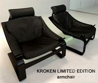
KROKEN LIMITED EDITION
...d
rochebobois
autumn/winter collections 2012 rochebobois paris
kroken limited edition armchairhttp://m.roche-bobois.com
3ddd
$1
stilwerk limited edition
...stilwerk limited edition
3ddd
3000х1200х750
Da
3ddd
$1

Luce da Vivere
...luce da vivere
3ddd
luce da vivere
luce da vivere mary 387/6+3
3ddd
$1

Luce da Vivere
...luce da vivere
3ddd
luce da vivere
luce da vivere
cristalline 494/12 rosso/cromo
turbosquid
$6
Cabinet DA
...ty free 3d model cabinet da for download as max, fbx, and obj on turbosquid: 3d models for games, architecture, videos. (1637312)
turbosquid
$6
Bookcase DA
... free 3d model bookcase da for download as max, fbx, and obj on turbosquid: 3d models for games, architecture, videos. (1639996)
turbosquid
$5
Wardrobe DA
...y free 3d model wardrobe da for download as max, fbx, and obj on turbosquid: 3d models for games, architecture, videos. (1661117)
turbosquid
$5
Partition DA
... free 3d model partition da for download as max, fbx, and obj on turbosquid: 3d models for games, architecture, videos. (1640359)
3ddd
$1
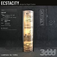
Ecstacity_LAMPADA DA TERRA
...ecstacity_lampada da terra
3ddd
ecstacity
торшер ecstacity_lampada da terra
3ddd
$1
leonardo da vinci
...leonardo da vinci
3ddd
всадник , лошадь
leonardo da vinci
turbosquid
$60

DA-ExoticWeapons
... available on turbo squid, the world's leading provider of digital 3d models for visualization, films, television, and games.
turbosquid
$32
DA-SpikedChainMace
... available on turbo squid, the world's leading provider of digital 3d models for visualization, films, television, and games.
2
design_connected
$11
No 2
...no 2
designconnected
sibast no 2 computer generated 3d model. designed by sibast, helge.
turbosquid
$6
Cliff Rock 2-2
...uid
royalty free 3d model cliff rock 2-2 for download as obj on turbosquid: 3d models for games, architecture, videos. (1619161)
turbosquid
$29

Book variation 2 2
...3d model book variation 2 2 for download as max, obj, and fbx on turbosquid: 3d models for games, architecture, videos. (1366868)
turbosquid
$22
Classic baluster (2) (2)
...assic baluster (2) (2) for download as max, obj, fbx, and stl on turbosquid: 3d models for games, architecture, videos. (1483789)
turbosquid
$99

Smilodon 2 Pose 2
... available on turbo squid, the world's leading provider of digital 3d models for visualization, films, television, and games.
turbosquid
$20
Barrel Barricade 2-2
... available on turbo squid, the world's leading provider of digital 3d models for visualization, films, television, and games.
turbosquid
$6
Wall Trophy (2) (2)
... available on turbo squid, the world's leading provider of digital 3d models for visualization, films, television, and games.
turbosquid
free
Tire label 2 of 2
... available on turbo squid, the world's leading provider of digital 3d models for visualization, films, television, and games.
3ddd
$1
Кровать, 2 тумбочки, 2 светильника
...кровать, 2 тумбочки, 2 светильника
3ddd
кровать, 2 тумбочки, 2 светильника
нормальное качество
формат 3ds max
без текстур
3ddd
free

Кровать, 2 тумбочки, 2 светильника
...кровать, 2 тумбочки, 2 светильника
3ddd
кровать, 2 тумбочки, 2 светильника
нормальное качество
формат 3ds max
без текстур