Thingiverse
Da Vinci 1.0A mobile push notification by traveltje
by Thingiverse
Last crawled date: 3 years ago
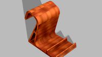
This “thing” will send a Push notification to your mobile device when your 3D print is ready.
It uses an ESP8266, Endstop and the Pushbullet service/app.
It will cost about 3 Euro to make and the service is completely free :)
You will need:
1) Davinci 1.0A
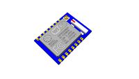
2) ESP8266 board. This can be a D1 mini, Luna, ESP12 chip or any other ESP8266 board.
I used this one: http://www.aliexpress.com/item/New-Wireless-module-CH340-NodeMcu-V3-Lua-WIFI-Internet-of-Things-development-board-based-ESP8266-We/32565317233.html?ws_ab_test=searchweb201556_10,searchweb201602_3_10037_10017_405_404_10032_10040,searchweb201603_11&btsid=8fc48ede-0e4a-4bda-90ce-e016cce5ad1a
3) PushBullet account
4) Mobile device with the PushBullet App installed
5) Endstop like: http://www.aliexpress.com/item/1PCS-High-Quality-Mechanical-Endstop-without-the-wheel-For-Reprap-ramps-1-4-3D-printer/32623871393.html?ws_ab_test=searchweb201556_10,searchweb201602_3_10037_10017_405_404_10032_10040,searchweb201603_11&btsid=31098e6d-7719-4f38-8d7c-87987b602cb4
6) 3D printer :-p
7) Repetier firmware.
Optional you will need some wires and a soldering iron for step 13.
Step 1:
Create a free Pushbullet account: https://www.pushbullet.com
Step 2:
Download Pushbullet app on your mobile device (Phone, Tablet..) and login with your credentials.
Step 3:
Create a Pushbullet “API key”.
You can find it on https://www.pushbullet.com under Settings->Account->Access Tokens.
Step 4:
Copy the ESP8266 Arduino code (ESP code.txt) to your Arduino IDE, change the dots “.…” and upload it to your ESP board:
const char* ssid = "…"; Your Wifi SSID.
const char* password = "…"; Your Wifi password.
const char* PushBulletAPIKEY = "…"; Your PushBullet API key that you created in step 3.
Step 5:
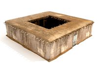
3D Print the STL files:
I used ABS but PLA should be fine.
Layer Height 0.3
Infill 20%
No support material.
Step 6:
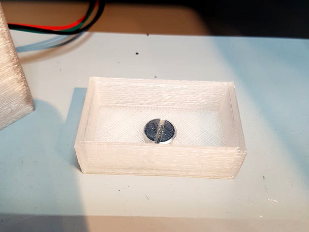
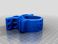
Screw (I used the original packaging screw) the “Bottom” part to the printer as seen in pictures 1 and 2.
Step 7:
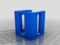
Insert the Endstop and wiring in the “Top” part as seen in pictures 3 and 4.
Insert the wires first.
Step 8:
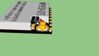
Connect the Endstop to pin 5 on the ESP and Ground + 3.3V.
I used GPIO 5 because on my ESP board pin 5 is next to Ground and 3V3, this way I can use the wires that came with the Endstop. See picture 8.
Step 9:
Perform a test by clicking on the Endstop. (Don’t forget to power your ESP8266 :) )
If all went well you should receive a notification on your mobile device.
Step 10:
Push the Top part in the Bottom part as seen in picture 5.
Step 11:
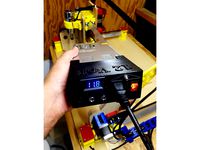
Set your Repetier printer settings to “park position Z min 172 mm” as seen in picture 10.
You might want to check the exact height for your printer by manually adjusting the Z until it clicks the Endstop. I don’t know if all Davinci 1.0A are built exactly the same.
Step 12:
Turn on the ESP8266 and print something :) Have fun!
Optional:
Step 13:
Open the printers back cover and solder wires directly to the Ground and 3.3V pins as seen on picture 11. Connect these wires and the Endstop wires to the ESP8266 module and place the module somewhere next to the PCB. There is plenty of room behind the back cover.
This step turns the ESP8266 on/off when you turn the printer on/off and also makes everything look nice as seen on picture 6, there is no ESP module in sight.
It uses an ESP8266, Endstop and the Pushbullet service/app.
It will cost about 3 Euro to make and the service is completely free :)
You will need:
1) Davinci 1.0A
2) ESP8266 board. This can be a D1 mini, Luna, ESP12 chip or any other ESP8266 board.
I used this one: http://www.aliexpress.com/item/New-Wireless-module-CH340-NodeMcu-V3-Lua-WIFI-Internet-of-Things-development-board-based-ESP8266-We/32565317233.html?ws_ab_test=searchweb201556_10,searchweb201602_3_10037_10017_405_404_10032_10040,searchweb201603_11&btsid=8fc48ede-0e4a-4bda-90ce-e016cce5ad1a
3) PushBullet account
4) Mobile device with the PushBullet App installed
5) Endstop like: http://www.aliexpress.com/item/1PCS-High-Quality-Mechanical-Endstop-without-the-wheel-For-Reprap-ramps-1-4-3D-printer/32623871393.html?ws_ab_test=searchweb201556_10,searchweb201602_3_10037_10017_405_404_10032_10040,searchweb201603_11&btsid=31098e6d-7719-4f38-8d7c-87987b602cb4
6) 3D printer :-p
7) Repetier firmware.
Optional you will need some wires and a soldering iron for step 13.
Step 1:
Create a free Pushbullet account: https://www.pushbullet.com
Step 2:
Download Pushbullet app on your mobile device (Phone, Tablet..) and login with your credentials.
Step 3:
Create a Pushbullet “API key”.
You can find it on https://www.pushbullet.com under Settings->Account->Access Tokens.
Step 4:
Copy the ESP8266 Arduino code (ESP code.txt) to your Arduino IDE, change the dots “.…” and upload it to your ESP board:
const char* ssid = "…"; Your Wifi SSID.
const char* password = "…"; Your Wifi password.
const char* PushBulletAPIKEY = "…"; Your PushBullet API key that you created in step 3.
Step 5:
3D Print the STL files:
I used ABS but PLA should be fine.
Layer Height 0.3
Infill 20%
No support material.
Step 6:
Screw (I used the original packaging screw) the “Bottom” part to the printer as seen in pictures 1 and 2.
Step 7:
Insert the Endstop and wiring in the “Top” part as seen in pictures 3 and 4.
Insert the wires first.
Step 8:
Connect the Endstop to pin 5 on the ESP and Ground + 3.3V.
I used GPIO 5 because on my ESP board pin 5 is next to Ground and 3V3, this way I can use the wires that came with the Endstop. See picture 8.
Step 9:
Perform a test by clicking on the Endstop. (Don’t forget to power your ESP8266 :) )
If all went well you should receive a notification on your mobile device.
Step 10:
Push the Top part in the Bottom part as seen in picture 5.
Step 11:
Set your Repetier printer settings to “park position Z min 172 mm” as seen in picture 10.
You might want to check the exact height for your printer by manually adjusting the Z until it clicks the Endstop. I don’t know if all Davinci 1.0A are built exactly the same.
Step 12:
Turn on the ESP8266 and print something :) Have fun!
Optional:
Step 13:
Open the printers back cover and solder wires directly to the Ground and 3.3V pins as seen on picture 11. Connect these wires and the Endstop wires to the ESP8266 module and place the module somewhere next to the PCB. There is plenty of room behind the back cover.
This step turns the ESP8266 on/off when you turn the printer on/off and also makes everything look nice as seen on picture 6, there is no ESP module in sight.
Similar models
thingiverse
free

Box for ESP8266, ESP-12E WiFi Module NodeMcu by MartinDubois
...box for esp8266, esp-12e wifi module nodemcu by martindubois
thingiverse
box for esp8266, esp-12e wifi module nodemcu
grabcad
free

ESP8266 WIFI Module 2.4G 802.11bgn ESP-06
...esp8266 wifi module 2.4g 802.11bgn esp-06
grabcad
esp8266 wifi
grabcad
free

ESP-12F (ESP8266)
... esp8266 chip. i tried to take into account all sizes and fonts. thanks to https://grabcad.com/alex.fedorov-3/ for the led model.
grabcad
free

ESP Relay Modul
...esp relay modul
grabcad
esp8266 relais mit esp8266 serielles wifi-transceiver-modul esp-01s
grabcad
free

ESP8266-12 WiFi
...esp8266-12 wifi
grabcad
esp wifi module
grabcad
free

ESP-07S WiFi module
...abcad
esp-07s wifi module is developed by ai-thinker co.,ltd, core processor esp8266 in smaller sizes of the
module encapsulates
grabcad
free

Wemos D1 Mini
...ule for wemos lua 4m bytes wlan wifi internet development board base on esp8266 esp-12f for arduino,compatible with wemos d1 mini
3dwarehouse
free
ESP8266 ESP-07 Wi Fi Module for Eagle CAD
...odule for eagle cad
3dwarehouse
wifi esp8266 esp-07 16-pin module for eagle cad, , assembled from artworks of different authors.
thingiverse
free

expression pedal remix by Kozobrod
...(line: rotat = round(((analogread(sensorpin)-17)*127/900)); )
for pc use rtpmidi programm
video link: https://t.me/couchmakers/31
3dwarehouse
free
ESP8266 ESP-07S WIFI Module
...esp8266 esp-07s wifi module
3dwarehouse
i got a little carried away.
Traveltje
thingiverse
free

Ornament ceiling by traveltje
...ornament for a lamp on the ceiling. made it using:https://www.thingiverse.com/thing:227663https://www.thingiverse.com/thing:36564
thingiverse
free
12 volt case by traveltje
...12 volt case by traveltje
thingiverse
had to change a few holes for my parts.
credits to the original design!
thingiverse
free
Nema 17 - 45mm spacer by traveltje
...nema 17 - 45mm spacer by traveltje
thingiverse
i could only buy 70mm m3 screws so i made the 50mm spacer a little bit shorter..
thingiverse
free

Root 3 Y carrage holder by traveltje
...age holder by traveltje
thingiverse
needed a simple way to secure the y carriage to the build plate.
this holder does the trick.
thingiverse
free
MGN 12 Spindle mount 56mm by traveltje
...nese cnc spindle is 55mm in the middle and the top is even 56.6mm so i had to make the hole in this part 56mm to make it all fit.
0A
turbosquid
free

0a Latin Girl Head
... available on turbo squid, the world's leading provider of digital 3d models for visualization, films, television, and games.
turbosquid
free
0a GI John - The Stone
... available on turbo squid, the world's leading provider of digital 3d models for visualization, films, television, and games.
turbosquid
$9

Dinning Table & Chair `141128`0A
... available on turbo squid, the world's leading provider of digital 3d models for visualization, films, television, and games.
thingiverse
free

rice4T
...used later pictureshttps://www.reddit.com/r/mechanicalkeyboards/comments/ejocz9/first_ever_keyboard_3d_printed_hand_wired_where/ link to the keyboard layout editor http://www.keyboard-layout-editor.com/##@@=esc&_a:0%3b&=q%0a0a%0a%0a1%0a!&=w%0a%0a%0a%0a2%0a%2f@&=e%0a%0a%0a%0a3%0a%23&=r%0a%0a%0a%0a4%0a$&=t%0a%0a%0a%0a5%0a%25&=y%0a%0a%0a%0a6%0a%5e&=u%0a%0a%0a%0a7%0a%2f&&=i%0a%0a%0a%0a8%0a*&=o%0a%0a%0a%0a9%0a(&=p%0a%0a%0a%0a0%0a)&_w:1.25%3b&=back%3cbr%3espace%0a%0a%0a%0a%0adel&_a:4&f:2%3b&=mute%0aencoder%0a%0a%0a%0a%0avolume%3b&@_f:3&w:1.25%3b&=tab&_a:0%3b&=a%0a%0a%0a%0af1&=s%0a%0a%0a%0af2&=d%0a%0a%0a%0af3&=f%0a%0a%0a%0af4&=g%0a%0a%0a%0af5&=h%0a%0a%0a%0af6%0a-&=j%0a%0a%0a%0a%0a%2f=&=k%0a%0a%0a%0a%0a%5b&=l%0a%0a%0a%0a%0a%5d&=%2f%2f%0a%3f%0a%0a%0a%0a%5c&_a:4&w:1.5%3b&=enter%3b&@_w:1.75%3b&=shift&_a:0%3b&=z%0a%0a%0a%0af7&=x%0a%0a%0a%0af8&=c%0a%0a%0a%0af9&=v%0a%0a%0a%0af10&=b%0a%0a%0a%0af11&=n%0a%0a%0a%0af12%0a%2f%3b&=m%0a%0a%0a%0a%0a'&_a:4%3b&=%3c%0a,&=%3e%0a.&_a:7%3b&=%e2%86%91&_a:4%3b&=shift%3b&@_w:1.25%3b&=ctrl&=lgui&=alt&_a:7%3b&=%e2%86%91&_w:2.25%3b&=&=%e2%86%93&_a:4%3b&=alt&_w:1.25%3b&=ctrl&_a:7%3b&=%e2%86%90&=%e2%86%93&=%e2%86%92 ...
3d_sky
$8

Axo_light
...axo_light 3dsky axo light axo light, table lamp http://www.lumens.com/ax20-adjustable-wall-sconce-by-axo-light-uu325371.html#cgid=%0a09%0a%09%098690%0a%09%0a&&tileindex=2 ...
thingiverse
free

SD9VE/SIGMA Magazine Spring Baseplate by AEGIS_DEFENCE_CORP
...sd9ve/sigma magazine spring baseplate by aegis_defence_corp thingiverse adc part m-002-0a magazine spring baseplate direct replacement part for sd9ve/sigma...
thingiverse
free

Trx4 battery tray raiser to fit 37mm thick battery by huxq
...hardcase 5300mah 3s lipo there. view the result video here:https://www.youtube.com/watch?v=wcmmyunl-0aamp;ab_channel=shawnhue ...
thingiverse
free

SD9VE/SIGMA Magazine +6/7 Round Extension by AEGIS_DEFENCE_CORP
...aegis_defence_corp thingiverse aegis defence corp. model: sd9-ve/sigma 9mm part: cm-9-01-0a1002 +6/7 round extension for standard issue sd9ve magazine requires:...
thingiverse
free

NEMA 23 bowden extruder MK7 1,75mm by Dmitriy_dd
...mk7 1,75mm by dmitriy_dd thingiverse nema23 mount https://ru.aliexpress.com/item/nema-23-57-steppr-motor-accessories-bracket-support-shelf-mounting-l-bracket-mount-step-stepping-stepper/32325368491.html?spm=2114.13010608.0.0.tco2wz&detailnewversion=&categoryid=100007155 nema23 https://ru.aliexpress.com/item/special-8mmshaft-wantai-4-lead-nema23-stepper-motor-57bygh627d8l25-2-270oz-in-76mm-3-0arouter/32645762883.html?spm=2114.13010608.0.0.tco2wz mk7 drive gear bore 8mm 1.75mm https://ru.aliexpress.com/item/printer-accessories-extruder-drive-gear-bore-8mm-1-75mm-gear-stainless-steel-extruder-wheel-for-mk7/32551783778.html?spm=2114.13010608.0.0.uowidc aluminum extrusion...
thingiverse
free

E3D v5 and v6 40x40 Fan Duct remix (firmness and air flow) by 011000101101
...used these drawings for getting the right dimensions when remixing:https://wiki.e3d-online.com/images/7/7d/drawing-v5-sink.jpghttps://wiki.e3d-online.com/images/0/0adrawing-v6-175-sink.png btw i'm using both v5 and v6 right now...
Notification
turbosquid
$5

3d social media notification like icon
...royalty free 3d model like icon for download as blend and obj on turbosquid: 3d models for games, architecture, videos. (1675956)
3d_export
$7

Bubble Notification Icon Set
... also have a lot more different character models. you may see it in my profile.<br>i hope you enjoy my design. thank you :)
3d_ocean
$2

Post-It
...post-it 3docean it notice notification office paper post post-it tack tic work *originally created...
3d_export
$5

OnePlus 6
...houses the front-facing camera, ambient light sensor, and led notification<br>objects: 21<br>vertices: 10988<br>edges: 20314<br>faces: 9313<br>triangles:...
3d_export
$25

Radar
...translation for all the accompanying elements of your application (notification, pop-ups etc.). moreover, we offer separate translation and adaptation...
3d_export
$25

Rifle
...translation for all the accompanying elements of your application (notification, pop-ups etc.). moreover, we offer separate translation and adaptation...
3d_export
$19

Water Tower
...translation for all the accompanying elements of your application (notification, pop-ups etc.). moreover, we offer separate translation and adaptation...
3d_export
$19

Generator
...translation for all the accompanying elements of your application (notification, pop-ups etc.). moreover, we offer separate translation and adaptation...
3d_export
$17
Gun sights Collimator sight
...translation for all the accompanying elements of your application (notification, pop-ups etc.). moreover, we offer separate translation and adaptation...
3d_export
$9
Container
...translation for all the accompanying elements of your application (notification, pop-ups etc.). moreover, we offer separate translation and adaptation...
Vinci
3d_export
$9

clcok vinci
...clcok vinci
3dexport
clcok vinci
3ddd
$1
willisau vinci chair
...willisau vinci chair
3ddd
willisau , vinci
vinci chair from willisau ag.
design_connected
$13

Vinci chair
...vinci chair
designconnected
willisau vinci chair computer generated 3d model. designed by ballendat, martin.
3ddd
$1

BOVA-комод-vinci
...bova-комод-vinci
3ddd
bova , комод
bova-комод-vinci
3ddd
$1
leonardo da vinci
...leonardo da vinci
3ddd
всадник , лошадь
leonardo da vinci
3d_export
$25

a - leonardo da vinci
...a - leonardo da vinci
3dexport
a - leonardo da vinci<br>antiquity
turbosquid
$10

Pouf Vinci
...ty free 3d model pouf vinci for download as max, obj, and fbx on turbosquid: 3d models for games, architecture, videos. (1507069)
turbosquid
$30

Da Vinci
... available on turbo squid, the world's leading provider of digital 3d models for visualization, films, television, and games.
3d_export
$25
machine- leonardo da vinci
...machine- leonardo da vinci
3dexport
machine- leonardo da vinci
3d_export
$25

mortar - leonardo da vinci
...mortar - leonardo da vinci
3dexport
mortar - leonardo da vinci
Push
3ddd
$1

Pushe
...pushe
3ddd
pushe
pushe
3ddd
$1

Pushe
...pushe
3ddd
pushe
диван pushe
3ddd
$1

PUSHE
...pushe
3ddd
pushe , угловой
размер 320x260 см
3ddd
$1

Pushe / Hilton
...pushe / hilton
3ddd
om , pushe
pushe / hilton
3ddd
$1
Pushe / Enio
...pushe / enio
3ddd
om , pushe
pushe / enio
3ddd
$1

Pushe / Volana
...pushe / volana
3ddd
om , pushe
pushe / volana
3ddd
$1
Pushe / Адорес
...pushe / адорес
3ddd
om , pushe
pushe / адорес
3ddd
$1

Pushe / Kosta
.../ kosta
3ddd
om , pushe , угловой
pushe / kosta
3ddd
$1

Pushe / Narciss
...rciss
3ddd
om , pushe , угловой
pushe / narciss
3ddd
$1
Pushe / Grande
...grande
3ddd
om , pushe , угловой
pushe / grande
Mobile
3ddd
$1

Mobil Piu
...mobil piu
3ddd
mobil piu , капитоне
кровать mobil piu
turbosquid
$10
mobile
...urbosquid
royalty free 3d model mobile for download as blend on turbosquid: 3d models for games, architecture, videos. (1385101)
turbosquid
$1

Mobile
...uid
royalty free 3d model mobile for download as fbx and obj on turbosquid: 3d models for games, architecture, videos. (1607690)
3d_export
$5
Mobile Holder
...mobile holder
3dexport
new mobile holder
turbosquid
$55

Mobile
... available on turbo squid, the world's leading provider of digital 3d models for visualization, films, television, and games.
turbosquid
$20

Mobile
... available on turbo squid, the world's leading provider of digital 3d models for visualization, films, television, and games.
turbosquid
$20

mobile
... available on turbo squid, the world's leading provider of digital 3d models for visualization, films, television, and games.
turbosquid
$10

MOBILE
... available on turbo squid, the world's leading provider of digital 3d models for visualization, films, television, and games.
turbosquid
$9

mobile
... available on turbo squid, the world's leading provider of digital 3d models for visualization, films, television, and games.
turbosquid
$1

Mobile
... available on turbo squid, the world's leading provider of digital 3d models for visualization, films, television, and games.
Da
3ddd
$1

Luce da Vivere
...luce da vivere
3ddd
luce da vivere
luce da vivere mary 387/6+3
3ddd
$1

Luce da Vivere
...luce da vivere
3ddd
luce da vivere
luce da vivere
cristalline 494/12 rosso/cromo
turbosquid
$6
Cabinet DA
...ty free 3d model cabinet da for download as max, fbx, and obj on turbosquid: 3d models for games, architecture, videos. (1637312)
turbosquid
$6

Bookcase DA
... free 3d model bookcase da for download as max, fbx, and obj on turbosquid: 3d models for games, architecture, videos. (1639996)
turbosquid
$5
Wardrobe DA
...y free 3d model wardrobe da for download as max, fbx, and obj on turbosquid: 3d models for games, architecture, videos. (1661117)
turbosquid
$5

Partition DA
... free 3d model partition da for download as max, fbx, and obj on turbosquid: 3d models for games, architecture, videos. (1640359)
3ddd
$1
Ecstacity_LAMPADA DA TERRA
...ecstacity_lampada da terra
3ddd
ecstacity
торшер ecstacity_lampada da terra
3ddd
$1
leonardo da vinci
...leonardo da vinci
3ddd
всадник , лошадь
leonardo da vinci
turbosquid
$60

DA-ExoticWeapons
... available on turbo squid, the world's leading provider of digital 3d models for visualization, films, television, and games.
turbosquid
$32
DA-SpikedChainMace
... available on turbo squid, the world's leading provider of digital 3d models for visualization, films, television, and games.
1
turbosquid
$69

armchairs(1)(1)
... available on turbo squid, the world's leading provider of digital 3d models for visualization, films, television, and games.
turbosquid
$15
ring 1+1
... available on turbo squid, the world's leading provider of digital 3d models for visualization, films, television, and games.
turbosquid
$10

chair(1)(1)
... available on turbo squid, the world's leading provider of digital 3d models for visualization, films, television, and games.
turbosquid
$8

Chair(1)(1)
... available on turbo squid, the world's leading provider of digital 3d models for visualization, films, television, and games.
turbosquid
$2

RING 1(1)
... available on turbo squid, the world's leading provider of digital 3d models for visualization, films, television, and games.
turbosquid
$1
house 1(1)
... available on turbo squid, the world's leading provider of digital 3d models for visualization, films, television, and games.
turbosquid
$1

Table 1(1)
... available on turbo squid, the world's leading provider of digital 3d models for visualization, films, television, and games.
turbosquid
$59

Formula 1(1)
...lty free 3d model formula 1 for download as max, fbx, and obj on turbosquid: 3d models for games, architecture, videos. (1567088)
design_connected
$11
No 1
...no 1
designconnected
sibast no 1 computer generated 3d model. designed by sibast, helge.
turbosquid
$2
desert house(1)(1)
...3d model desert house(1)(1) for download as 3ds, max, and obj on turbosquid: 3d models for games, architecture, videos. (1055095)