Thingiverse
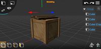
cube based system for decoration and technical applications
by Thingiverse
Last crawled date: 4 years, 2 months ago
Next: will move over the gaming dice related stuff to a separate thing.
Latest addition:
3x3 LED schematics circuit (BETA)
3x3 LED pcb (BETA), outlines 38x38mm (40x40mm) image size 60x60mm, 1200 dpi
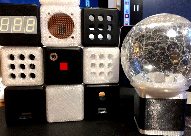
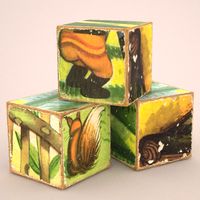
This is my take on making ( do not read raking in big money) a whole system of parts based on the cubes shape.
Mixing the parts together makes decoration, technical devices, switches, displays with LED,...
Put your pcb's in:
inside top part
before the top part
in the middle of the mid section
before the bottom part
inside the bottom part
Even more? Depends on the layer thicknes of each slice (pcb with parts and solder on the copper) plus some clearance distance between the stacked pcb's.
See below the old scholl pcb stack cube.
All parts are designed for lightwight application.
When you put something heavy on the mount / stand, please upright only.
Now almost all parts have the unified holes distances.
.
Have you ever wanted to put as much as possible electronics in a tight space?
Make a stack from pcb's.
See below pointer to Harald Sattlers website.https://cdn.thingiverse.com/assets/de/34/41/d5/2c/featured_preview_stack1.JPG
See the pictures, it gives you the imagination, what is possible.
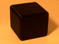
The pieces of foam (black and white) are 5mm thick).
shown with no batteries inside.
.
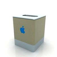
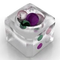
The inspiration came from the Heliox LED dice.
The way she made it pulled me hairs. No good.
I had it primarily intended for decorating the living room.
Imagine blinking up to 9 dot LED's instead of the 6 LED on the classic dice.
A LED matrix made of 9 rectangular LED (10x10mm) could be made?
Even small animations, kind of running snake, could be made.
See a short video sequence
Rename the "dice red on black.mp4.txt", by removing the .txt extension.
With the 7-segment LED other applications can be had.
Now it has turned to a measuring frontpanel thing too.
Lets think about :
exposure-timer
egg-timer
3 minutes teeth brushing timer for the kids
Thermometer,
Humidity-meter
Volt-meter could check the voltage from power supply, car batterie, etc.
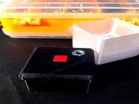
The power plug and the switch at the bottom get connected and secured in place by a separate pcb.
The mobile things can be powered by a cell coin or Super Capacitor.
NEW: Power from 2 pieces Akku AA 2/3 size
On permanent setups powering from external source.
The construction (mechanical):
For esthetical reason initially the dice measured 43x43x40mm.
Some demanding applications could require more space inside.
By printing a taller mid section it could be changed easily.
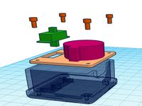
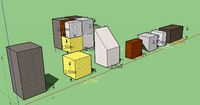
The dice can be build from 3 parts.
Choose one for the top, one for the bottom and allways the mid bottom.
All printable parts have been drawn from scratch.
All new parts have standoffs.
With the mid section (39.6mm) I have achieved a VERY good fit.
new parts come here sometimes
-battery holder 2AA 2/3 Akku, part goes inside the mid section
-bottom part with switch and holder 2AA 2/3 Akku
solid part for top / bottom, no extras
top / bottom with plug and switch
top with hidden 9 dot LED 5mm diameter
top / front with hidden 7-segment LED
top / front with visable 7-segment LED (hard to print)
top cut out 30.1x30.1mm (slightly wider hole distances)
mount plate with flange 64x64mm8
new bottom part for switch and some other stuff you might put in inside (Beta)
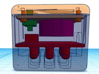
-clearance between pcb and the bottom inside the parts cave 7mm
-the switch goes downward
-standoffs holes distance 31mm
-standoffs 9mm hight, for thin plastic screws
-there is jut enough space for the switch and a holder for a cell coin( CR2032-CR2025),
cell holders are to tall, go topward
new bottom part with switch and 2x 2/3AA batteries (Beta) different hole spacing
The mid section, goes in between the top and bottom part.
If your printer works halfway dimensionally accurat try the part with the smaller inner diameter first.
mid section 39.6x43x43x31mm (raw from editor)
mid section 39.7x43x43x31mm (raw from editor)
mid section 40.0x43x43x31mm (raw from editor)https://www.thingiverse.com/thing:3926580
Parts used (electronics):
3* 7-segment LED TFK TDR5160
3.5mm DC Power Jack Socket Female Panel Chassis Mount
shaft diameter 7.4mm
flange diameter 9.8mm
overall length with leads 16,7mm
body length 12mm
the monentary push button switch used
By chance the switch were made by France /USA based C&K, 25 years back in time.https://www.ckswitches.com/products/keyswitch/KS/
shape rectangular: square 9.9-10mm
travel 0,6mm
overall hight with leads: 11.3mm
body hight with cap without the positioning pins: 6.8mm
body without cap withoutpositioning pins: 6mm
Switches, other candidates:
RAFI (Germany) Of course, no CHINEESE CHEESE please
Racon 8 (width 8mm) used for industrial keyboards, automotive applications
The switch can be combined with several long/short pushers, caps.
0.34mm - thats not much travel! But it is doable.
.https://components.rafi.de/DE/DE/media/FOT_PV_RACON8-THT-OS_ING.jpg
Very similar the Racon12 series, little bigger sized
Taster S76M (mechanical switch)
force from 2,3N bis 12 N (automotive application)
Codes:
There are some codes driving the ATTiny13 in question.
some of them require the Arduino IDE other do with Atmel Studio IDE.
Build the ATTiny13 dice on a perfboard, quick and dirty.http://www.weise-bernd.de/?p=691http://www.weise-bernd.de/?p=669http://www.weise-bernd.de/wp-content/uploads/2018/03/AtTiny13_Wuerfel_v1_01-170x300.jpghttp://www.weise-bernd.de/wp-content/uploads/2018/04/IMG_20180311_1854321-e1523802126100-270x300.jpg
See the DL section, the code has the sleep mode.
When not activated the MCU goes to sleep draws a tiny current I could not measure.
Hints:
Check the size inside the parts first before you start designing your pcb layout.
I will try to settle with a guarantied size of 37x37mm for the top and bottom parts.
The areas have rounded corners!
As of writing the areas are a little over 37mm.
To stay safe the pcb size 37mm x 37mm should do fine.
Inside the mid section and the foot mounting plate thing is room for almost 40x40mm.
I beleive a maximum of pcb size 39.5x39.5mm should be ok here.
If you encounter many artifacts on the surface of the printed parts try the raw files instead.
Usually my stl-files have been sent trough Netfab for repair.
.
Stack pcb's see Harald Sattlers website-->>http://www.harald-sattler.de/assets/images/TN_WF3_MiniOffenK.JPGhttp://www.harald-sattler.de/Wuerfel2_Diagram.jpg
Easy but no ATTiny, using clock generator made from transistors, 7492 counter, decoder logic made from a bunch of diodes.
.
Power the electronics from Super Capacitor
Mr Sattler desribes his conversion of a CR2032 driven DS3231RTC module with Super Condensator (German:Doppelschicht-Kondensator)http://www.harald-sattler.de/html/wordclock.htm#UmbauMiniModulhttp://www.harald-sattler.de/assets/images/autogen/2018-09-20_IMG_4884_resize.jpg
.
Replace the mechanical switch
by a capacitive approximation switch, triggered by 50/60 Hz field next to any electrical circuit.
No software requiered, simple hardware only.http://stefan-franke.net/elektronik/kapazitiver-schalter
Translated (trough google service) website as a pdf-file in the DL section
Latest addition:
3x3 LED schematics circuit (BETA)
3x3 LED pcb (BETA), outlines 38x38mm (40x40mm) image size 60x60mm, 1200 dpi
This is my take on making ( do not read raking in big money) a whole system of parts based on the cubes shape.
Mixing the parts together makes decoration, technical devices, switches, displays with LED,...
Put your pcb's in:
inside top part
before the top part
in the middle of the mid section
before the bottom part
inside the bottom part
Even more? Depends on the layer thicknes of each slice (pcb with parts and solder on the copper) plus some clearance distance between the stacked pcb's.
See below the old scholl pcb stack cube.
All parts are designed for lightwight application.
When you put something heavy on the mount / stand, please upright only.
Now almost all parts have the unified holes distances.
.
Have you ever wanted to put as much as possible electronics in a tight space?
Make a stack from pcb's.
See below pointer to Harald Sattlers website.https://cdn.thingiverse.com/assets/de/34/41/d5/2c/featured_preview_stack1.JPG
See the pictures, it gives you the imagination, what is possible.
The pieces of foam (black and white) are 5mm thick).
shown with no batteries inside.
.
The inspiration came from the Heliox LED dice.
The way she made it pulled me hairs. No good.
I had it primarily intended for decorating the living room.
Imagine blinking up to 9 dot LED's instead of the 6 LED on the classic dice.
A LED matrix made of 9 rectangular LED (10x10mm) could be made?
Even small animations, kind of running snake, could be made.
See a short video sequence
Rename the "dice red on black.mp4.txt", by removing the .txt extension.
With the 7-segment LED other applications can be had.
Now it has turned to a measuring frontpanel thing too.
Lets think about :
exposure-timer
egg-timer
3 minutes teeth brushing timer for the kids
Thermometer,
Humidity-meter
Volt-meter could check the voltage from power supply, car batterie, etc.
The power plug and the switch at the bottom get connected and secured in place by a separate pcb.
The mobile things can be powered by a cell coin or Super Capacitor.
NEW: Power from 2 pieces Akku AA 2/3 size
On permanent setups powering from external source.
The construction (mechanical):
For esthetical reason initially the dice measured 43x43x40mm.
Some demanding applications could require more space inside.
By printing a taller mid section it could be changed easily.
The dice can be build from 3 parts.
Choose one for the top, one for the bottom and allways the mid bottom.
All printable parts have been drawn from scratch.
All new parts have standoffs.
With the mid section (39.6mm) I have achieved a VERY good fit.
new parts come here sometimes
-battery holder 2AA 2/3 Akku, part goes inside the mid section
-bottom part with switch and holder 2AA 2/3 Akku
solid part for top / bottom, no extras
top / bottom with plug and switch
top with hidden 9 dot LED 5mm diameter
top / front with hidden 7-segment LED
top / front with visable 7-segment LED (hard to print)
top cut out 30.1x30.1mm (slightly wider hole distances)
mount plate with flange 64x64mm8
new bottom part for switch and some other stuff you might put in inside (Beta)
-clearance between pcb and the bottom inside the parts cave 7mm
-the switch goes downward
-standoffs holes distance 31mm
-standoffs 9mm hight, for thin plastic screws
-there is jut enough space for the switch and a holder for a cell coin( CR2032-CR2025),
cell holders are to tall, go topward
new bottom part with switch and 2x 2/3AA batteries (Beta) different hole spacing
The mid section, goes in between the top and bottom part.
If your printer works halfway dimensionally accurat try the part with the smaller inner diameter first.
mid section 39.6x43x43x31mm (raw from editor)
mid section 39.7x43x43x31mm (raw from editor)
mid section 40.0x43x43x31mm (raw from editor)https://www.thingiverse.com/thing:3926580
Parts used (electronics):
3* 7-segment LED TFK TDR5160
3.5mm DC Power Jack Socket Female Panel Chassis Mount
shaft diameter 7.4mm
flange diameter 9.8mm
overall length with leads 16,7mm
body length 12mm
the monentary push button switch used
By chance the switch were made by France /USA based C&K, 25 years back in time.https://www.ckswitches.com/products/keyswitch/KS/
shape rectangular: square 9.9-10mm
travel 0,6mm
overall hight with leads: 11.3mm
body hight with cap without the positioning pins: 6.8mm
body without cap withoutpositioning pins: 6mm
Switches, other candidates:
RAFI (Germany) Of course, no CHINEESE CHEESE please
Racon 8 (width 8mm) used for industrial keyboards, automotive applications
The switch can be combined with several long/short pushers, caps.
0.34mm - thats not much travel! But it is doable.
.https://components.rafi.de/DE/DE/media/FOT_PV_RACON8-THT-OS_ING.jpg
Very similar the Racon12 series, little bigger sized
Taster S76M (mechanical switch)
force from 2,3N bis 12 N (automotive application)
Codes:
There are some codes driving the ATTiny13 in question.
some of them require the Arduino IDE other do with Atmel Studio IDE.
Build the ATTiny13 dice on a perfboard, quick and dirty.http://www.weise-bernd.de/?p=691http://www.weise-bernd.de/?p=669http://www.weise-bernd.de/wp-content/uploads/2018/03/AtTiny13_Wuerfel_v1_01-170x300.jpghttp://www.weise-bernd.de/wp-content/uploads/2018/04/IMG_20180311_1854321-e1523802126100-270x300.jpg
See the DL section, the code has the sleep mode.
When not activated the MCU goes to sleep draws a tiny current I could not measure.
Hints:
Check the size inside the parts first before you start designing your pcb layout.
I will try to settle with a guarantied size of 37x37mm for the top and bottom parts.
The areas have rounded corners!
As of writing the areas are a little over 37mm.
To stay safe the pcb size 37mm x 37mm should do fine.
Inside the mid section and the foot mounting plate thing is room for almost 40x40mm.
I beleive a maximum of pcb size 39.5x39.5mm should be ok here.
If you encounter many artifacts on the surface of the printed parts try the raw files instead.
Usually my stl-files have been sent trough Netfab for repair.
.
Stack pcb's see Harald Sattlers website-->>http://www.harald-sattler.de/assets/images/TN_WF3_MiniOffenK.JPGhttp://www.harald-sattler.de/Wuerfel2_Diagram.jpg
Easy but no ATTiny, using clock generator made from transistors, 7492 counter, decoder logic made from a bunch of diodes.
.
Power the electronics from Super Capacitor
Mr Sattler desribes his conversion of a CR2032 driven DS3231RTC module with Super Condensator (German:Doppelschicht-Kondensator)http://www.harald-sattler.de/html/wordclock.htm#UmbauMiniModulhttp://www.harald-sattler.de/assets/images/autogen/2018-09-20_IMG_4884_resize.jpg
.
Replace the mechanical switch
by a capacitive approximation switch, triggered by 50/60 Hz field next to any electrical circuit.
No software requiered, simple hardware only.http://stefan-franke.net/elektronik/kapazitiver-schalter
Translated (trough google service) website as a pdf-file in the DL section
Similar models
thingiverse
free
LED dice bottom Heliox remix
...25 years back in time. now tey have a similar looking ks series.https://www.ckswitches.com/products/keyswitch/ks/ the...
grabcad
free

4x 7 segment LED display PCB
...splay 67,2x24,0mm. dimensions pcb 69,2x35,0mm.
a smaller version see: https://grabcad.com/library/4x-7-segment-led-display-pcb-1
thingiverse
free
Heliox dice bottom part safety fix
...ndoff hight 5.5mm, short screws requiered
-fixed bottom part standoff hight 9.5mm, mount plane leveled up, longer screws possible
grabcad
free

4x 7 segment LED display PCB
...rabcad
a very small 4x7 seg 7 segment led display pcb. dimensions of the 4x7 segment led display 28x8mm. dimensions pcb 35x22mm.
thingiverse
free
3x3 LED Heliox cube remix collection
...iverse.com/thing:3926580
heliox arduino code.
arduino attiny85/45 support file (basically it is a link for the boardmanager only)
thingiverse
free

Thru-PCB LED light for Proxxon MB140/S drill stand by hlavaatch
...lled a hole in the side of the stand and put a standard dc power connector there for my 12v dc workbench supply to power the led.
thingiverse
free

Toy rocket, with USB lithium battery charger and LEDs by pheelan
... there is a usb slot, for the battery charger (under the rocket), and slots inside the base for retaining the battery charger pcb
thingiverse
free
LED cube 29mm standard dice edition
...system.https://www.thingiverse.com/thing:3926580 the cube size is 29mm. there is a similar cube thing i have designed and adopted to fit...
thingiverse
free

Dice Box - Cthulhu
...s a nice "finished" look to the dice box. i've included a model for the hex-shaped template i use to mark the felt.
thingiverse
free

Jack-O-Lantern Pumpkin With Bottom Opening For LED Tea Light by mb20music
...ing the tea light (from the bottom of the pumpkin) and holding the tea light in place.https://www.youtube.com/watch?v=2utrnle9zos
Cube
3d_ocean
$5
Cubes
...cubes
3docean
children cube cubes model paint toy toys wooden
old wooden children’s cubes.
3d_export
$5
cube
...cube
3dexport
cube
3d_export
$5

cube
...cube
3dexport
cube
3d_export
free

Chemistry cube - cube chimique
...chemistry cube - cube chimique
3dexport
chemistry cube - cube chimique
3d_export
$10

Cube
...cube
3dexport
cube deco
3d_export
free

cube
...cube
3dexport
invented the cube
archibase_planet
free
Cube
...cube
archibase planet
cube
g4 cube - 3d model for interior 3d visualization.
3d_export
$6
cube
...cube
3dexport
cube gamel location
archibase_planet
free
Cube
...cube
archibase planet
home furniture cube
cube - 3d model (*.gsm+*.3ds) for interior 3d visualization.
archibase_planet
free
Cube
...cube
archibase planet
cube block die
cube eazelcom n050113 - 3d model (*.gsm+*.3ds) for interior 3d visualization.
Technical
3ddd
$1
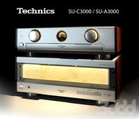
Technics
...итель technics: su-c3000 и se-a3000 (конец 90х).
ширина 480мм. fbx 4мб, сцена 368кб. полигоны 22 310 шт, кол-во без turbosmooth.
3ddd
$1

LEGO Technic
...ic - snowmobile (8272)
lego technic - quad bike (9392)
модельки делались в solid, экспортировались в max, материалы и рендер vray
3ddd
$1
LEGO Technic
...hoe grader (8862)
lego technic - backhoe loader (8455)
модельки делались в solid, экспортировались в max, материалы и рендер vray
3ddd
$1
Technics SB-T100
... колонки , сабфувер
колонки и сабфувер technics sb-t100
turbosquid
$8
Technics Amplifier
...3d model technics amplifier for download as max, obj, and fbx on turbosquid: 3d models for games, architecture, videos. (1503952)
turbosquid
$25

technical pen.max
... available on turbo squid, the world's leading provider of digital 3d models for visualization, films, television, and games.
3d_export
$20

Technical Park Inverter
...technical park inverter
3dexport
technical park inverter (loop fighter)
3ddd
$1

Technics SL1210M5G
...ом ±8%/±16%.
последняя из выпущенных на
данный момент моделей
не напрасно вызывает неподдельное восхищение у любителей музыки.
3d_export
$20
Technics 3D Model
...technics 3d model
3dexport
technics 3d model hristoff 64259 3dexport
3ddd
$1

LEGO Technic
...льки делались в solid, экспортировались в max, материалы и рендер vray
огромное спасибо lx3 за модельку гомера, он оживил рендер!
Applications
turbosquid
$11

Application Desk - 04
...yalty free 3d model application desk - 04 for download as c4d on turbosquid: 3d models for games, architecture, videos. (1524249)
turbosquid
$11

Application Desk - 03
...yalty free 3d model application desk - 03 for download as c4d on turbosquid: 3d models for games, architecture, videos. (1524242)
turbosquid
$11
Application Desk - 02
...yalty free 3d model application desk - 02 for download as c4d on turbosquid: 3d models for games, architecture, videos. (1524228)
3d_export
$10

spikewheel applicator
...t popular formats: solidworks: *.sldprt *.slddrw *.sldasm (native) iges: *.iges *.igs step: *.step *.stp stereolithography: *.stl
3d_export
$10

liquid fertilizer applicator
...t popular formats: solidworks: *.sldprt *.slddrw *.sldasm (native) iges: *.iges *.igs step: *.step *.stp stereolithography: *.stl
turbosquid
$30

Prop 'Medieval' Design, Frame for window or door Depends on application
...r window or door depends on application for download as max on turbosquid: 3d models for games, architecture, videos. (1708095)
3d_export
$12

cross 3d relief for vectric and artcam applications
... zip archive with the 3d model. instant download immediately after payment! we guarantee high quality of all presented 3d models.
3d_export
$36

shiv parvati 3d relief for vectric and artcam applications
...inters. it works with artcam, aspire, cut3d, 3d max. after purchase, you will able to download the zip archive with the 3d model.
3d_export
$38

ganesh god 3d relief for vectric and artcam applications
... zip archive with the 3d model. instant download immediately after payment! we guarantee high quality of all presented 3d models.
3d_export
$12

lion decor 3d relief for vectric and artcam applications
... zip archive with the 3d model. instant download immediately after payment! we guarantee high quality of all presented 3d models.
System
archibase_planet
free
System
...m
archibase planet
fire alarm system fire alarm box
security light system - 3d model (*.gsm+*.3ds) for interior 3d visualization.
archibase_planet
free
Spider system
...stem spider glass system
spider system to fix glass stefano galli n050912 - 3d model (*.gsm+*.3ds) for interior 3d visualization.
3ddd
$1
Euforia System
...euforia system
3ddd
euforia
euforia system
3d_export
$50
Roof system Truss system 3D Model
...oof system truss system 3d model
3dexport
roof system truss truss stage
roof system truss system 3d model aleksbel 38970 3dexport
3ddd
$1
DVD System
...dvd system
3ddd
dvd , schneider
dvd system
design_connected
free
Seating system
...seating system
designconnected
free 3d model of seating system
3d_export
$5

solar system
...solar system
3dexport
solar system in c4d, with 8k nasa textures
3ddd
$1
Quanta System
...quanta system
3ddd
медицина
quanta system.
лазерное оборудование для медицинских центров
3d_export
$15
solar system
...nd the other the sun, the earth and the moon, the latter has an animation with camera movement included, the files are in spanish
3d_export
$14

missile system
...missile system
3dexport
Decoration
3d_ocean
$3
Decoration
...arabic.arab decoration decorative plaster isalm islamic other decorative objects panel pattern stone wall
decoration for building
3d_ocean
$3

Decoration
...sic arabic.arab decoration decorative plaster isalm islamic other decorative objects panel pattern stone wall
decoration plaster…
3d_export
$10
decor
...decor
3dexport
decor
3d_export
$5

decor
...decor
3dexport
decor
archibase_planet
free

Decor
...decor archibase planet decor statuette decoration leaf decor 2 - 3d model (*.gsm+*.3ds) for interior...
3d_export
$10

decor
...decor
3dexport
lattice decor
3ddd
$1
DECOR
...decor
3ddd
панель
decor
3ddd
$1
Decor
...decor
3ddd
панель
decor
3ddd
$1
Decor
...decor
3ddd
панель
decor
3ddd
free
DECOR
...decor
3ddd
панель
decor
Based
archibase_planet
free
Base
...base
archibase planet
base column column base
base 1 - 3d model (*.gsm+*.3ds) for interior 3d visualization.
archibase_planet
free
Base
...base
archibase planet
base column base column
base 5 - 3d model (*.gsm+*.3ds) for interior 3d visualization.
archibase_planet
free
Base
...base
archibase planet
base column column base
base 7 - 3d model (*.gsm+*.3ds) for interior 3d visualization.
archibase_planet
free
Base
...base
archibase planet
base column column base
base 2 - 3d model (*.gsm+*.3ds) for interior 3d visualization.
archibase_planet
free
Base
...base
archibase planet
base column column base
base 3 - 3d model (*.gsm+*.3ds) for interior 3d visualization.
archibase_planet
free
Base
...base
archibase planet
base column column base
base 4 - 3d model (*.gsm+*.3ds) for interior 3d visualization.
archibase_planet
free
Base
...base
archibase planet
base column base column
base 6 - 3d model (*.gsm+*.3ds) for interior 3d visualization.
archibase_planet
free
Base
...base
archibase planet
foundation base
column base ionic - 3d model (*.gsm+*.3ds) for interior 3d visualization.
archibase_planet
free
Base
...base
archibase planet
foundation base
column base tuscan - 3d model (*.gsm+*.3ds) for interior 3d visualization.
design_connected
$18
Base
...base
designconnected
tom dixon base computer generated 3d model. designed by dixon, tom.