Thingiverse
CTC PRUSA i3 Pro B Bowden Drive with Autoleveling by triggermeister
by Thingiverse
Last crawled date: 3 years ago
UPDATE 3/15/2018
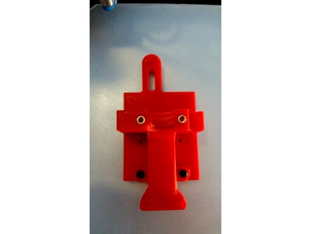
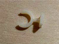
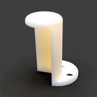
Rossano95 shared his modified retainer. I removed the non-working and replaced it with his. Give Rossano95 a shout out if you use it! ;-)
UPDATE 3/14/2018
Rossano95 tested the 18mm mount version and it worked! The retainer didn't fit very well so he redesigned it. He may post as a remix or if he sends it to me I'll post it here.
UPDATE 3/11/2018
I added a untested hotend mount for a 18mm sensor. I don't plan on ever using it, so print it at your own risk.
UPDATE 1/6/2018
The blasted 2mm glass worked great...for a while. Unfortunately the last print stuck too good to the blasted glass and some glass came off when I pulled the part off. So I'm I went back to the hardware store and picked up another piece of glass. Adhesion is just fine with Ammonia cleaned class (Windex or any off brand window cleaner), but not as good as the blasted glass.
UPDATE 12/30
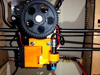
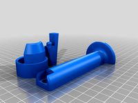
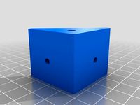
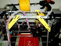
I decided to print the STL and it turned out great. I put in 4 brass inserts and then mounted the whole thing from the back in the lower position via the brass inserts instead of the lower mounting holes. I also bead blasted the glass which seems to help with adhesion. Please note that the duct is adjustable via the oval mounting holes. I had to mount it in the all the way up position to give it clearance between the nozzle and the bed.
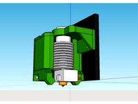
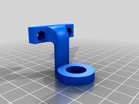
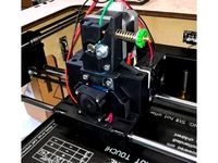
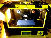
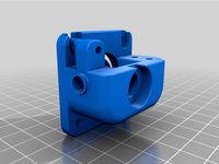
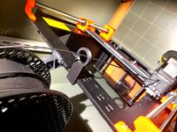
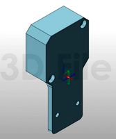
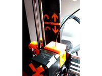
My CTC hotend broke and I was without a 3D printer. Luckily, I am in the process of building a HEVO and therefore I had the mount, hotend, extruder, retainer and duct already on hand. By drilling two extra holes and removing a little plastic near the X endstop flag in the mount, I made it fit the CTC carriage perfectly. Again, since my printer was down, I didn't design this in CAD and just modified the piece I had by hand and then created the STL for thingiverse so no guarantees that it will fit. I left a bridge in there for support that you will have to break out and I put in two mounting options; one way the way I mounted it by drilling holes, and another for mounting it with M3 brass fittings to lower the mount closer to the bed. The HEVO mount has the proximity probe spot already, so I figured I should add that sensor as well.
If you are ready for a double mod, keep reading...
Items Needed:
Soldering Iron
several connectors
connector wires (from breadboard)
Arduino IDE
an extra Arduino as ISP to update the bootloader on the CTC Aduino
Marlin firmware
BOM:
1 x 5V NPN M12 inductive sensorhttps://www.aliexpress.com/item/M12-4mm-detection-5VDC-NPN-NO-LJ12A3-4-Z-BX-5V-cylinder-inductive-proximity-sensor-switch/32553311139.html?spm=2114.13010608.0.0.iDrnoz
3D Printer Accessories V6 J-Head Hotend RepRap Extruder for 1.75mm Filament, Direct Feed or Bowden. w/ 0.4mm Nozzle, 12V fan, and 3ft PTFE Bowden Tube
ALPTAhttp://a.co/9PxYSl4
8.5" x 8.5" galvanized 28ga metal plate to place between the hotbed and glass plate. This ensures that the sensor is triggered properly. Without it you will need to either not use glass or you are going to be very close to the nozzle level. Ferrous metals are the best at triggering proximity sensors, that's why I didn't use aluminium.
8.5" x 8.5" x 0.880" glass plate. I prefer to print on glass.
Extruder of your choice (e.g. find one on thingiverse)
Process
Prepare and install your material for your heat bed. Cut the galvanized plate with some metal shears to size. IMPORTANT: make sure the metal does not short out any contacts on the heated bed. You need to cut around those areas!.
Get the glass plate from your a hardware store. They will cut it to size if you ask nicely. You need the corners angled to have room for the screw heads.
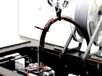
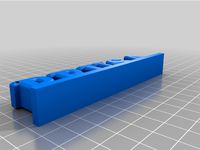
Prepare and install the J hotend and proximity sensor with the extruder mount, retainer and duct from the HEVO project.
Solder the 5V and Ground connections to the board. I chose to use add a connector for easy disconnect.
Make a backup of the original settings. These were mine:
15:07:46.286 : echo:Hardcoded Default Settings Loaded
15:07:46.286 : echo:Steps per unit:
15:07:46.287 : echo: M92 X78.74 Y78.74 Z2560.00 E105.00
15:07:46.287 : echo:Maximum feedrates (mm/s):
15:07:46.287 : echo: M203 X400.00 Y400.00 Z2.00 E45.00
15:07:46.287 : echo:Maximum Acceleration (mm/s2):
15:07:46.287 : echo: M201 X1400 Y1400 Z100 E80000
15:07:46.287 : echo:Acceleration: S=acceleration, T=retract acceleration
15:07:46.287 : echo: M204 S1400.00 T5000.00
15:07:46.287 : echo:Advanced variables: S=Min feedrate (mm/s), T=Min travel feedrate (mm/s), B=minimum segment time (ms), X=maximum XY jerk (mm/s), Z=maximum Z jerk (mm/s), E=maximum E jerk (mm/s)
15:07:46.287 : echo: M205 S0.00 T0.00 B20000 X13.50 Z0.30 E5.00
15:07:46.287 : echo:Home offset (mm):
15:07:46.287 : echo: M206 X0.00 Y0.00 Z0.00
15:07:46.287 : echo:PID settings:
15:07:46.287 : echo: M301 P19.86 I1.00 D98.93
Upgrade your bootloader. Here is how to do it: NOTE: I simply used the standard SD card cable and plugged in bread board wires into the one end. So I didn't need to find a ribbon cable that I could cut up! I also added a pictures of the connectors.
Time to download, configure and install Marlin. Use the GEEETECH example in the examples folder as a base. I attached my Configuration.h file here for reference with auto leveling enabled: https://www.thingiverse.com/download:4494314 . Using this config will consume 94% of the memory. So there is hardly anything left for additional features.
Last but not least make sure you adjust the z-axis in the LCD until you get the nozzle in the correct location (mine was -0.25). Then make sure you save your settings.
*ANOTHER BENEFIT of UPGRADING YOUR FIRMWARE**
The CTC is over-extruding (at least mine was). In Cura I had set the correction in the start script, but with the new firmware I changed the E stepper from 105 to 95 in the configuration.h, so no more start code fix needed!
Rossano95 shared his modified retainer. I removed the non-working and replaced it with his. Give Rossano95 a shout out if you use it! ;-)
UPDATE 3/14/2018
Rossano95 tested the 18mm mount version and it worked! The retainer didn't fit very well so he redesigned it. He may post as a remix or if he sends it to me I'll post it here.
UPDATE 3/11/2018
I added a untested hotend mount for a 18mm sensor. I don't plan on ever using it, so print it at your own risk.
UPDATE 1/6/2018
The blasted 2mm glass worked great...for a while. Unfortunately the last print stuck too good to the blasted glass and some glass came off when I pulled the part off. So I'm I went back to the hardware store and picked up another piece of glass. Adhesion is just fine with Ammonia cleaned class (Windex or any off brand window cleaner), but not as good as the blasted glass.
UPDATE 12/30
I decided to print the STL and it turned out great. I put in 4 brass inserts and then mounted the whole thing from the back in the lower position via the brass inserts instead of the lower mounting holes. I also bead blasted the glass which seems to help with adhesion. Please note that the duct is adjustable via the oval mounting holes. I had to mount it in the all the way up position to give it clearance between the nozzle and the bed.
My CTC hotend broke and I was without a 3D printer. Luckily, I am in the process of building a HEVO and therefore I had the mount, hotend, extruder, retainer and duct already on hand. By drilling two extra holes and removing a little plastic near the X endstop flag in the mount, I made it fit the CTC carriage perfectly. Again, since my printer was down, I didn't design this in CAD and just modified the piece I had by hand and then created the STL for thingiverse so no guarantees that it will fit. I left a bridge in there for support that you will have to break out and I put in two mounting options; one way the way I mounted it by drilling holes, and another for mounting it with M3 brass fittings to lower the mount closer to the bed. The HEVO mount has the proximity probe spot already, so I figured I should add that sensor as well.
If you are ready for a double mod, keep reading...
Items Needed:
Soldering Iron
several connectors
connector wires (from breadboard)
Arduino IDE
an extra Arduino as ISP to update the bootloader on the CTC Aduino
Marlin firmware
BOM:
1 x 5V NPN M12 inductive sensorhttps://www.aliexpress.com/item/M12-4mm-detection-5VDC-NPN-NO-LJ12A3-4-Z-BX-5V-cylinder-inductive-proximity-sensor-switch/32553311139.html?spm=2114.13010608.0.0.iDrnoz
3D Printer Accessories V6 J-Head Hotend RepRap Extruder for 1.75mm Filament, Direct Feed or Bowden. w/ 0.4mm Nozzle, 12V fan, and 3ft PTFE Bowden Tube
ALPTAhttp://a.co/9PxYSl4
8.5" x 8.5" galvanized 28ga metal plate to place between the hotbed and glass plate. This ensures that the sensor is triggered properly. Without it you will need to either not use glass or you are going to be very close to the nozzle level. Ferrous metals are the best at triggering proximity sensors, that's why I didn't use aluminium.
8.5" x 8.5" x 0.880" glass plate. I prefer to print on glass.
Extruder of your choice (e.g. find one on thingiverse)
Process
Prepare and install your material for your heat bed. Cut the galvanized plate with some metal shears to size. IMPORTANT: make sure the metal does not short out any contacts on the heated bed. You need to cut around those areas!.
Get the glass plate from your a hardware store. They will cut it to size if you ask nicely. You need the corners angled to have room for the screw heads.
Prepare and install the J hotend and proximity sensor with the extruder mount, retainer and duct from the HEVO project.
Solder the 5V and Ground connections to the board. I chose to use add a connector for easy disconnect.
Make a backup of the original settings. These were mine:
15:07:46.286 : echo:Hardcoded Default Settings Loaded
15:07:46.286 : echo:Steps per unit:
15:07:46.287 : echo: M92 X78.74 Y78.74 Z2560.00 E105.00
15:07:46.287 : echo:Maximum feedrates (mm/s):
15:07:46.287 : echo: M203 X400.00 Y400.00 Z2.00 E45.00
15:07:46.287 : echo:Maximum Acceleration (mm/s2):
15:07:46.287 : echo: M201 X1400 Y1400 Z100 E80000
15:07:46.287 : echo:Acceleration: S=acceleration, T=retract acceleration
15:07:46.287 : echo: M204 S1400.00 T5000.00
15:07:46.287 : echo:Advanced variables: S=Min feedrate (mm/s), T=Min travel feedrate (mm/s), B=minimum segment time (ms), X=maximum XY jerk (mm/s), Z=maximum Z jerk (mm/s), E=maximum E jerk (mm/s)
15:07:46.287 : echo: M205 S0.00 T0.00 B20000 X13.50 Z0.30 E5.00
15:07:46.287 : echo:Home offset (mm):
15:07:46.287 : echo: M206 X0.00 Y0.00 Z0.00
15:07:46.287 : echo:PID settings:
15:07:46.287 : echo: M301 P19.86 I1.00 D98.93
Upgrade your bootloader. Here is how to do it: NOTE: I simply used the standard SD card cable and plugged in bread board wires into the one end. So I didn't need to find a ribbon cable that I could cut up! I also added a pictures of the connectors.
Time to download, configure and install Marlin. Use the GEEETECH example in the examples folder as a base. I attached my Configuration.h file here for reference with auto leveling enabled: https://www.thingiverse.com/download:4494314 . Using this config will consume 94% of the memory. So there is hardly anything left for additional features.
Last but not least make sure you adjust the z-axis in the LCD until you get the nozzle in the correct location (mine was -0.25). Then make sure you save your settings.
*ANOTHER BENEFIT of UPGRADING YOUR FIRMWARE**
The CTC is over-extruding (at least mine was). In Cura I had set the correction in the start script, but with the new firmware I changed the E stepper from 105 to 95 in the configuration.h, so no more start code fix needed!
Similar models
thingiverse
free
E3D Hotend mount for CTC Prusa i3 DIY with 40mm fan and filament cooling by MartinHoffmann
...xisting screw holes in the ctc diy where the extruder was mounted.
for mounting you need six 15 mm m3 screws and six square nuts.
thingiverse
free

Prusa i3 Bowden Hotend mount with radial fan and a parametrizable inductive proximity sensor by kilpelaj
...ity_sensor_v2.stl" from the original design. that is where you can also get the other parts like the fan duct and the clamp.
thingiverse
free

FT5 Proximity sensor mount front plate by whiteb68
...ft5 proximity sensor mount front plate by whiteb68
thingiverse
ft5 extruder carriage front plate for a proximity sensor
thingiverse
free
Proximity sensor mount remix for Wilson direct drive extruder. by milkypostman
...didn't try to fix and just heated the nuts to melt them into the countersinks and drilled the holes out. but it works great.
thingiverse
free
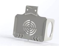
Proximity Sensor Mount - Auto Bed Levelling by MightyLAD
...r.
proximity sensor i used is - lj12a3-4-z/bx (inductive npn - so no resistors needed on ramps - ace!)
the mount hole is dia 12mm
thingiverse
free

Bed levelling sensor mount for CTC / Flashforge by slippyr4
...is needs the soft end stops (travel limits) to be reduced to stop the printer ramming the sensor into the left hand x axis mount.
thingiverse
free

Geeetech Prusa i3 Groove Mount by ctodish
...on't need the sensor (you may want to print an extra one to use as a spacer if your hotend ends up too close to the x plate).
thingiverse
free

CTC i3 Proximity Sensor Holder Mount (Back Side) by cdesp
...stance from the nozzle is 80mm.
if you want the sensor on the right side check this out.https://www.thingiverse.com/thing:2872351
thingiverse
free

Extended Proximity Sensor Mount for i3 Rework E3D Extruder by MrFanForced
...emixed it by extending the length of the mount (to fit my extruder) and also by extending it outwards from the extruder slightly.
thingiverse
free

Proximity sensor mount for LJ18A3-8-Z/BX 8mm sensor for Wilson or Prusa i3 by BiOGoly
...n direct drive extruder. i increased the diameter of the holder so that it can accommodate a lj18a3-8-z/bx 8mm proximity sensor.
Triggermeister
thingiverse
free

Barrel Lock Plug by triggermeister
...erse
if you have a barrel lock on something and you no longer need/want it, you can unscrew it and put this plug in place of it.
thingiverse
free

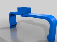
HEVO 13mm Bed Bracket by triggermeister
...ingiverse
just in case you need to loose a coupe of millimeters. in my case it was 2mm per bracket, hence the new 13mm bracket.
thingiverse
free

YAE... Yet Another Extruder by triggermeister
...me of the others designs, but the drive gear i had matched this design. this will require some sanding/fitting, but works great.
thingiverse
free

Hodgdon 1lbs container cap by triggermeister
...but i thought just a generic cap or a cap with letters could be good for someone out there. customize it to your hearts content.
thingiverse
free

Toilet Handle Holder Spacer...#PRINTSOMETHINGUNIQUE by triggermeister
... you may need to trim due to porcelain tolerances or use calipers and design your own! beer and plumbers crack are not required.
thingiverse
free
Dillon 1050 LED light bar / Light Visor by triggermeister
...ed lights, this is a simple print to help you light up your dillon 1050 without blinding you. very simple design, but effective.
thingiverse
free

Bullet feeder Slinky Spring Quick Disconnect by triggermeister
...dded tom penn's stl to my downloads section as well for historical purposes (just in case he modifies the one he has posted).
thingiverse
free
Linear Rail Slot Covers 3030 Extrusion - Hide your wires! by triggermeister
...find it while searching...
3030 rail x 160mm
3030 rail x 80mm
3030 rail x 50mm
3030 rail x 30mm
3030 rail x 20mm
3030 rail x 10mm
thingiverse
free

Zevex Enteral (MOOG) feeding pump bag hook by triggermeister
...b. the piece of filament will prevent the hook from falling off then knob when unhooking the bag. see the pictures for details.
thingiverse
free

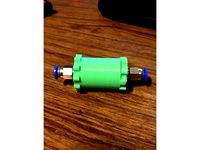
Cayston Emergency replacement connector by triggermeister
... and get hooked to the groves (see pictures).
good luck!
p.s. if you don't have a printer, you can use crocodile clips too.
Autoleveling
thingiverse
free

Autolevel by Lo_Copio_too
...autolevel by lo_copio_too
thingiverse
autolevel.
https://youtu.be/9idq1xy8i6i
thingiverse
free

Autolevel Fix by Kevinalign
...autolevel fix by kevinalign
thingiverse
to fix the bar of the optic autolevel, with a 3m screw
thingiverse
free

TronxyX5 Autolevel Holder
...tronxyx5 autolevel holder
thingiverse
tronxy x5 holder for pl-08n autolevel sensor
thingiverse
free

Silenciador de autolevel - Autolevel silencer by BFBA
...need to be corrected with a file after printing in order to work properly. the autolevel installed is a "3d touch" one.
thingiverse
free

Silenciador de autolevel - Autolevel silencer by BFBA
...need to be corrected with a file after printing in order to work properly. the autolevel installed is a "3d touch" one.
thingiverse
free

autolevel probe retractor by mming1106
...autolevel probe retractor by mming1106
thingiverse
autolevel probe retractor
thingiverse
free

easy autolevel by obdiy
...easy autolevel by obdiy thingiverse simple carriage for z- autoleveling for direct-drive extruders (i use...
thingiverse
free

Autolevel probe by eca3d
...robe by eca3d
thingiverse
autolevel probe for printer rostock.
description here: http://eca3d.blogspot.ru/2014/05/rostock-5.html
thingiverse
free

Autolevel Gehäuse by IW3D
...el gehäuse by iw3d
thingiverse
selbstgebauter autolevel sensor mit gehäuse mit deckel
material pla von bq orange 1.75 nozzel 0,4
thingiverse
free
Autolevel FLSUN QQ-S
...el flsun qq-s
thingiverse
autolevel switch
with https://aliexpress.ru/item/32915708033.html?spm=a2g0s.9042311.0.0.274233edtlbqkq
Ctc
turbosquid
$4

CTC Railroad Telephone
... available on turbo squid, the world's leading provider of digital 3d models for visualization, films, television, and games.
turbosquid
$7
Onibus Ciferal Padron Briza Volvo B58e CTC Azul
...briza volvo b58e ctc azul for download as blend, fbx, and obj on turbosquid: 3d models for games, architecture, videos. (1692482)
3dfindit
free
CTC
...ctc
3dfind.it
catalog: rcm
thingiverse
free
CTC by apone4
...ctc by apone4
thingiverse
modifica per ctc montaggio e3d
thingiverse
free
Filiamenthalter CTC by e2mars
...filiamenthalter ctc by e2mars
thingiverse
filiamenthalter ctc makebot
thingiverse
free
CTC's Feet by zion_taron
...ctc's feet by zion_taron
thingiverse
feet to ctc printers
thingiverse
free
CTC Abdeckung by Einstein77
...ctc abdeckung by einstein77
thingiverse
abdeckung für die hinteren bohrungen im gehäuse des ctc
thingiverse
free
CTC Corner caps by KyoFR
...ctc corner caps by kyofr
thingiverse
corner caps ctc
thingiverse
free
FILAMENT GUIDE CTC by HugoNogier
...filament guide ctc by hugonogier
thingiverse
filament guide ctc
thingiverse
free
CTC Bizer Fusshalter by FPV57
...ctc bizer fusshalter by fpv57
thingiverse
haltewinkel für gummifüsse ctc
Bowden
turbosquid
$199
Vintage Ben Bowden Spacelander bike
... available on turbo squid, the world's leading provider of digital 3d models for visualization, films, television, and games.
3ddd
$1

Manooi Artica
...and pendants in various sizes and forms. suspension: galvanized bowden - dia. 1,5 mm. bulb: max 60 w -...
thingiverse
free
Remix Compact Bowden extruder - m6 bowden couplers and bowden tube pass-through
...ouplers and bowden tube pass-through
thingiverse
remix compact bowden extruder - m6 bowden couplers and bowden tube pass-through
thingiverse
free

Bowden Extruder
...bowden extruder
thingiverse
i have created bowden extruder for flsun delta 3d printer.
thingiverse
free

bowden 3mm by spee_D
...bowden 3mm by spee_d
thingiverse
for bowden 3mm
thingiverse
free
Bowden Tube Cutter
...bowden tube cutter
thingiverse
bowden tube cutter
thingiverse
free
Customizable Bowden Clip
...customizable bowden clip
thingiverse
customizable bowden clip
thingiverse
free
Bowden Oiler by fcheshire
...bowden oiler by fcheshire
thingiverse
inline bowden oiler
thingiverse
free

Bowden adapter by helkaroui
...bowden adapter by helkaroui
thingiverse
this is a fixed bowden adapter
thingiverse
free

Adventure3 Bowden Clip
...adventure3 bowden clip
thingiverse
adventure3 bowden clip
I3
3d_export
$10
suv i3
...suv i3
3dexport
suv i3 2013 series
3d_ocean
$89
BMW i3 2012
...y, in real units of measurement, qualitatively and maximally close to the original. model formats: - *.max (3ds max 2008 scanl...
cg_studio
$99

BMW i3 20143d model
...
cgstudio
.3ds .c4d .fbx .lwo .max .obj - bmw i3 2014 3d model, royalty free license available, instant download after purchase.
cg_studio
$99

BMW i3 20123d model
...tudio
.3ds .c4d .fbx .lwo .max .mb .obj - bmw i3 2012 3d model, royalty free license available, instant download after purchase.
cg_studio
$99

BMW i3 20143d model
...tudio
.3ds .c4d .fbx .lwo .max .mb .obj - bmw i3 2014 3d model, royalty free license available, instant download after purchase.
humster3d
$75
3D model of BMW i3 2014
...
buy a detailed 3d model of bmw i3 2014 in various file formats. all our 3d models were created maximally close to the original.
humster3d
$40

3D model of Kitchen Set I3
...uy a detailed 3d model of kitchen set i3 in various file formats. all our 3d models were created maximally close to the original.
3d_ocean
$30
Kitchen set i3
...ensils oven plates shelves sink table ware
kitchen set i3 include 3d models: cooker, oven, sink, cupboards, table, chair, plates.
3d_ocean
$89

BMW i3 2014
...y, in real units of measurement, qualitatively and maximally close to the original. model formats: - *.max (3ds max 2008 scanl...
cg_studio
$99

BMW i3 Concept 20113d model
...i3
.3ds .c4d .fbx .lwo .max .obj - bmw i3 concept 2011 3d model, royalty free license available, instant download after purchase.
Prusa
turbosquid
$2
Frame Filament Guide Clip-On for Prusa Mk3
...rame filament guide clip-on for prusa mk3 for download as stl on turbosquid: 3d models for games, architecture, videos. (1634730)
3d_export
free
prusa i3 mk3s laser mount for opt lasers
...to learn more about the blue laser technology that conceived the cutting and engraving laser heads from opt lasers, please visit:
turbosquid
free
Prusa small printer adapter holder
...er for download as ipt, skp, dwg, dxf, fbx, ige, obj, and stl on turbosquid: 3d models for games, architecture, videos. (1642936)
3d_export
$30

geisha by jonathan adler
...** i did a 3d printing test in the prusa software, you can find it among the attached images.<br>exchange:<br>.blend...
thingiverse
free

Prusa without Prusa (rc2) by madless
...prusa without prusa (rc2) by madless
thingiverse
just the main part of prusa rc2 faceshield, without writing.
enjoy :)
thingiverse
free
Prusa by acejbc
...prusa by acejbc
thingiverse
prusa knob info
m3 8mm screw
thingiverse
free
Prusa house
...prusa house
thingiverse
how prusa house could look like...
thingiverse
free

Prusa Mk2 "Fake Prusa" LCD cover by anraf1001
...r by anraf1001
thingiverse
version of prusa's lcd cover with "fake prusa" instead of "original prusa"
thingiverse
free
Prusa stabilizator by gutiueugen
...prusa stabilizator by gutiueugen
thingiverse
prusa stabilizator
thingiverse
free
Keychain Prusa by rbarbalho
...keychain prusa by rbarbalho
thingiverse
keychain with text prusa.
Drive
3d_export
$10

cycloidal drive
...cycloidal drive
3dexport
cycloidal drive
3d_ocean
$5
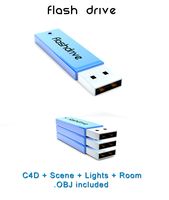
Flash Drive
...h drive included : – materials – scene ( lighs / room ) – .c4d + .obj for any questions please feel free to contact me thank you.
3d_ocean
$5
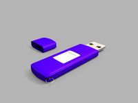
Usb drive
...s shaders and a lighting setup. it also has a small animation of it going in and out. i saved it out as both a .blend file and...
3d_ocean
$5

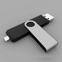
Pen Drive
...est computer drive game model good low poly new pen pen drive textured unwrapped uv very low poly
a very beautiful low poly model
3d_ocean
$10
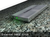
External hard drive
... is a detailed model of a trekstor external hard drive. you can easily modify the label on the top. simply edit the text objects.
turbosquid
$1

Flash Drive
...quid
royalty free 3d model flash drive for download as blend on turbosquid: 3d models for games, architecture, videos. (1231573)
turbosquid
$10
Flash Drive
...id
royalty free 3d model usb flash drive for download as obj on turbosquid: 3d models for games, architecture, videos. (1325282)
turbosquid
$1

USB Drive
...
royalty free 3d model usb drive for download as obj and fbx on turbosquid: 3d models for games, architecture, videos. (1701787)
3d_ocean
$4
USB Flash Drive
...usb flash drive
3docean
computer disk drive electronic flash mac memory pc pen usb
usb flash drive. the cartridge form
turbosquid
$10

Flash Drive
...y free 3d model flash drive for download as lxo, lxo, and obj on turbosquid: 3d models for games, architecture, videos. (1551742)
B
3ddd
$1
B&B
...b&b
3ddd
b&b italia
statue b&b italy
3ddd
$1
B&B Italia
...b&b italia
3ddd
b&b italia
b&b; italia
3ddd
$1

b&b italia
...b&b italia
3ddd
b&b italia
b&b; italia
3ddd
$1

B&B LAZY
...b&b lazy
3ddd
b&b italia
b&b; lazy
3ddd
$1
B&B Italy
...b&b italy
3ddd
b&b italia
диван b&b; italy
3ddd
$1

b&b RAY
...b&b ray
3ddd
b&b italia , угловой
диван b&b; ray
3ddd
$1
B&B Beverly
... b&b italia , beverly
cтул beverly от b&b.; текстуры в архиве
3ddd
$1

B&B ITALIA
...lia , журнальный , круглый
стол b&b; italia
3ddd
$1
шезлонг B&B
...шезлонг b&b
3ddd
b&b italia , шезлонг
шезлонг b&b; terminal 1
3ddd
$1

B&B J.J
...b&b j.j
3ddd
b&b italia , журнальный
b&b;
j.j
45x40x49 cm
Pro
turbosquid
$29
Pro
...ree 3d model mac pro for download as obj, c4d, fbx, and blend on turbosquid: 3d models for games, architecture, videos. (1505782)
3d_export
$5

iphone 13 pro max and pro
...3 pro max and 13 pro the model is made in four colors (graphite, gold, silver, and blue), all of which are attached in the files.
3d_export
free
sapphire pro
...sapphire pro
3dexport
sapphire pro 3d printer head mask
3d_export
$4

macbook pro
...macbook pro
3dexport
macbook pro 13" inch 2020 years model
3ddd
free
GentleLase Pro
... syneron , candela
gentlelase pro аппарат для лазерной эпиляции
turbosquid
$25

PRO frame
...rbosquid
royalty free 3d model pro frame for download as max on turbosquid: 3d models for games, architecture, videos. (1148329)
turbosquid
$5

Alien pro
...osquid
royalty free 3d model alien pro for download as blend on turbosquid: 3d models for games, architecture, videos. (1678446)
turbosquid
$5

iphone11 pro
...uid
royalty free 3d model iphone11 pro for download as blend on turbosquid: 3d models for games, architecture, videos. (1562707)
3ddd
$1
Mac Pro (appel)
...mac pro (appel)
3ddd
компьютер , apple
mac pro
3ddd
$1
Aviation PRO
... aviation
http://www.oligo.de/en/products/system-luminaires/prod/st-aviation-pro-1.html