Thingiverse
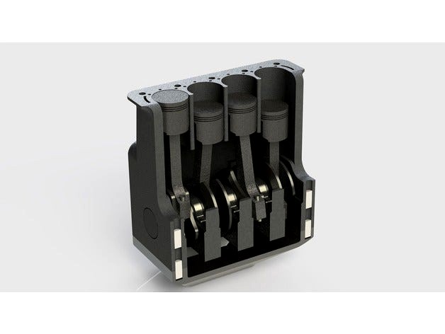
Crossplane I4 by chrisklam
by Thingiverse
Last crawled date: 3 years ago
Part List:
1X Crankcase
1X Upper Crankcase
1X Crankshaft
4X Piston Head
4X Wrist Pin
4X Connecting Rod
4X Rod cap
8X Connecting Rod Pin
3X Bearing Cap
1X Crank Lever
4X Crankcase Stud
Notes:
-The pins may take several prints to get right, since they are all slight press fits. Print all pins fully solid, they can break easily if you get them stuck in a part and try and finagle it out.
-Print the crankshaft standing up. Yes that'll be a lot of support, but it'll print more accurately
-Print the upper crankcase upside down (mating face of the head touching buildplate). This will also generate a lot of support material, but the bearing surfaces for the crankshaft need to be accurate
-Print the connecting rod with the upper hole vertical on the buildplate. Print the rod cap and bearing cap in the same fashion
-Print the piston head with the top of the cylinder against the build plate
-The connecting rod pins are slightly tapered. Make sure the larger diameter end of the pin is against the buildplate
-The lower crankcase can be printed normally with no supports needed
-The connecting rods & rod caps may need some slight sanding/filing to fit into the crankshaft. They should rotate smoothly when put together
-The connecting rod should also rotate freely around the wrist pin
-The engine can only spin one clockwise. Otherwise the pistons will detach from the cylinder walls (not a big deal)
-Lubrication might be a good idea, but I have not tried it
-Printed with a layer height of 0.8mm (pins printed at 0.1mm)
-If everything is goes right, you can spin it up reaaaaally freakin' fast with an electric drill
Assembly Order & Instructions:
Piston Assembly:Print Piston heads, connecting rods, and wrist pinsLine up upper connecting rod hole with piston head hole. Insert and press in wrist pin
*Connecting rod & piston head should rotate smoothly
Crankshaft Assembly:Print the lower crankcase (named Crankcase.stl), bearing caps, and crankshaftPlace crankshaft onto the lower crankcase and line up the grooves on both the crankshaft and crankcasePress bearing caps onto the crankcase pinsCrankshaft should rotate smoothly
Connecting Rod Assembly:This part can be a bit trickyPrint connecting rod pinsSlide piston assembly onto crankshaftTurn the crankshaft as much as necessary and press in the connecting rod pins
*Repeat 4X
Upper Crankcase Assembly:Print upper crankcase and crankcase pinsPress crankcase pins half way into the lower crankcaseWith all four pistons attached to the crankshaft, slide the upper crankcase over the pistons, lining up the pistons with the cylinder walls. Pistons may need to be snapped into the cylinder wallPress upper crankcase onto lower crankcase pinsAttach crank lever onto the square hole of the crankshaftMake sure everything rotates smoothly, if not, go back and sand/file the necessary parts
Similar models
grabcad
free

Four Cylinder Engine
...four cylinder engine
grabcad
connecting rop cap
connecting rod
crankshaft
piston head
piston pin
piston ring
grabcad
free

Single Piston Cylinder
...ylinder contains the following components:
1. piston pin
2. connecting rod
3. cylinder
4. crankshaft
5. upper case
6. lower case
grabcad
free

Four cylinder engine
... engine
grabcad
a complete design and assembly includes
pistion, crankshaft, piston pin, upper & lower block, connecting rod
grabcad
free

Single Cylinder Engine Cross-Section View
...gine with a cross-section view. the parts are the upper casing,lower casing, piston head, piston pin, crankshaft, and piston rod.
grabcad
free

Piston Assembly
...piston assembly
grabcad
its the full assembly of a piston, connecting rod, wrist pins, rod cap with bearings
grabcad
free

IC Engine Assembly
...lock and crankcase are brought together. this invention facilitates the assembly of the crankshaft, connecting rods, and pistons.
grabcad
free

Piston Assembly
...piston assembly
grabcad
parts include: piston head, connection rod, wrist pin, piston bushing and rod cap.
grabcad
free

Assembly of Connecting Rod
...at the angle between the connecting rod and the piston can change as the rod moves up and down and rotates around the crankshaft.
grabcad
free

bottompart block
...achined together with the cylinder block and assembled into the upper part of the crankcase after the crankshaft has been fitted.
grabcad
free

Four Cylinder Engine on Solidworks
...linder engine on solidworks
grabcad
1. piston
2. piston ring
3. crankshaft
4. connecting rod
5. connecting rod cap
6. piston pin
Crossplane
thingiverse
free

W Engines by petropixel
...available for download! i will be adapting this new (crossplane) crankshaft design to fit my vr engine...
thingiverse
free

Narrow Angle Vee Engines by petropixel
...with is almost there too. new alternate crankshafts: a crossplane one from my w engines for the vr6 and...
grabcad
free

Inline 4 crossplane
...inline 4 crossplane
grabcad
comically-proportioned inline 4 with an experimental crossplane crankshaft
grabcad
free

Crossplane Crankshaft
...pt visually from andreas gkertsos and modified to be crossplane like the yamaha yzf r1.
https://grabcad.com/library/crankshaft--5
grabcad
free

Piston -V8 Crossplane
...ight cylinder crankshaft-piston v8-crossplane engine to show how does it work this product takes one week to done by said ibrahim
cg_trader
free
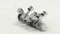
Piston V8 Crossplane
...ight cylinder crankshaft-piston v8-crossplane engine to show how does it work this product takes one week to done by said ibrahim
grabcad
free

Inline 3 cylinder engine crossplane crankshaft
...inline 3 cylinder engine crossplane crankshaft
grabcad
a crossplane crankshaft designed for inline 3 cylinder engine
grabcad
free

Crankshaft Assembly - 4.0 Liter (88mm X 80mm) Crossplane 120 Degree V-8
...ed induction). modeled a cross plane crankshaft and used modified connecting rods and pistons from my 2.0 liter engine project.
grabcad
free

Crankshaft
...solidworks as part of a project v8 engine. specifications: crossplane (0-270-180-90) length 114.5mm stroke length 15mm flange dia 30mm...
I4
3d_export
$69

bmw-i4
...vertisements or games corona render and materials all textures include in *.rar files lighting setup is not included in the file!
3ddd
$1

i4 Mariani Oyster
... oyster
кресло. i4 mariani, модель oyster.http://www.i4mariani.it/ing/home.html
3ddd
$1

кресло i4 Mariani blob
...кресло i4 mariani blob
3ddd
i4 mariani , blob
кресло i4 mariani blob
3ddd
$1

i4 Mariani Apollo
...i4 mariani apollo
3ddd
i4 mariani
включен файл для 3ds max 2012.
3ddd
$1

i4 MARIANI / manta
...i4 mariani / manta
3ddd
i4 mariani
итальянское кожаное кресло в двух цветовых решениях.
3ddd
$1
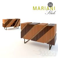
i4 Marinari - Slide
...modern design sideboard from i4 marinari. i couldn't find any dimensions of the product, so i designed it to my needs.
enjoy.
3d_export
$69

bmw-i4 m50
...vertisements or games corona render and materials all textures include in *.rar files lighting setup is not included in the file!
3ddd
$1

i4 Mariani SISSI Chair
...i4 mariani sissi chair
3ddd
i4 mariani
3ds max 2010.v-ray 2.40.03.file formats fbx,obj.i4 mariani sissi chair
3ddd
$1

i4 Mariani SISSI Chair
...i4 mariani sissi chair
3ddd
i4 mariani
3ds max 2010.v-ray 2.40.03.file formats fbx,obj,3ds.i4 mariani sissi chair
cg_studio
$25

i4 mariani Sofa Kate3d model
...a kate furniture
.fbx .obj .max - i4 mariani sofa kate 3d model, royalty free license available, instant download after purchase.