Thingiverse
CR10 Braces ( All CR10 Variants ) by mav68erick
by Thingiverse
Last crawled date: 3 years ago
EDIT!! Updated !!! Currently working on adapters for folks without a lathe or means to thread the brace rods. Will require a you to drill 4 3mm through holes though. stuffs in the works. Thanks https://www.thingiverse.com/thing:2749760
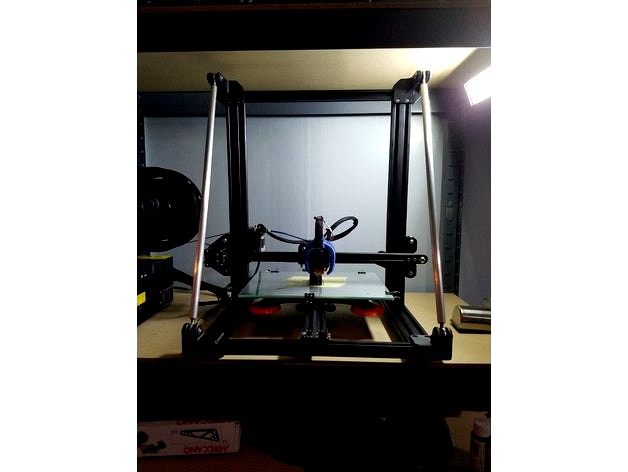
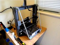
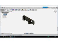
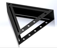
These are my design of the braces I saw on here. The others are for a CR10, I have a CR10 Mini, so the height and deepth are different, thus changing the angle of the threaded rod braces. I made this to be universal, although there is more work involved in them, and most people wont have a lathe or means to make the adjustable rods. Also the other braces you loose 12mm or so on your z Height, these you Do not. My Mini had a 300 Z height, which I can get about 305 out of it ( this all varies with peoples limit switch bed height etc. But at worst I loose maybe 1mm. so I still have my manufacturers claimed 300mm either way. The Extruder will hit the bottom of the upper Z Rod guide just before these braces hit the roller wheels on the side. So you can leave everything stock.
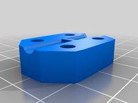
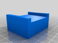
You will need to mirror each bracket!! 1 for each side of the printer. The stl is for the upper and the lower. Print the way I have them shown in Cura, I did them with and without supports. the vertical holes will be fine, its the very hole on the bottom that gets stringy but It still worked. I was going to add a small cylinder in fusion and make a pre modeled support but didnot. if your using S3D you can just add a support for just that hole.
These use 4mm and 5mm pan head screws with 4mm and 5mm t nuts ( hammer nuts )
Its a mix of the 2 because I had a 3-5mm kit I bought of amazon, and wanted to spread their use out.
Things to notice
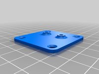
The brackets have an extra hole in them, that lines up with the 20x20 hole. if you so wish you can remove one of the bigger bolts holding the frame together temporarily and tap the hole 5mm. Giving you an extra mounting point. I didn't do this but added it anyways
There is clearance cut out where the extra hole is, because my printer had at most 1mm o over hang of the 20x20 to the 20x40mm. And to get by having to take it apart, mill off, or sand off, I added clearance to accommodate some factory imperfections.
There are also slight countersunk holes to allow room for the frame bolts. a few of mine stuck up past flush.
Getting the one 5mm screws in the top and the very front are tricky, you have to remove one of the frame bolts and put a t nut in, and put bolt back. They wont rotate in between the 2 bolt heads = (
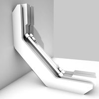
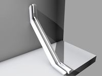
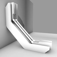
I used 1/4" spherical Rod ends with 1/2" aluminum rod. Drilled and Taped 1/4-28 Right hand thread on one end and left hand thread on the other so its adjustable. that way you can use a square and get your gantry perpendicular to it self.
Now I originally wanted to use 6mm hardware, but finding anything on amazon that I could get before Xmas, i switched to english. but! 6mm hardware will still fit! the hole is about 6.2mm anyways and I drilled it out to 1/4" and the width between where the rod end goes is .2mm wider. So you will just have a little more slop usng metric hardware, but if you tighten it, it wont matter. The only thing is the Nut hole will be a little more sloppy, but still fits.
my biggest worry when I was making these, was will a fang or fan fit. So i moved my setup to max Z and designed from there. See pictures.
These are my design of the braces I saw on here. The others are for a CR10, I have a CR10 Mini, so the height and deepth are different, thus changing the angle of the threaded rod braces. I made this to be universal, although there is more work involved in them, and most people wont have a lathe or means to make the adjustable rods. Also the other braces you loose 12mm or so on your z Height, these you Do not. My Mini had a 300 Z height, which I can get about 305 out of it ( this all varies with peoples limit switch bed height etc. But at worst I loose maybe 1mm. so I still have my manufacturers claimed 300mm either way. The Extruder will hit the bottom of the upper Z Rod guide just before these braces hit the roller wheels on the side. So you can leave everything stock.
You will need to mirror each bracket!! 1 for each side of the printer. The stl is for the upper and the lower. Print the way I have them shown in Cura, I did them with and without supports. the vertical holes will be fine, its the very hole on the bottom that gets stringy but It still worked. I was going to add a small cylinder in fusion and make a pre modeled support but didnot. if your using S3D you can just add a support for just that hole.
These use 4mm and 5mm pan head screws with 4mm and 5mm t nuts ( hammer nuts )
Its a mix of the 2 because I had a 3-5mm kit I bought of amazon, and wanted to spread their use out.
Things to notice
The brackets have an extra hole in them, that lines up with the 20x20 hole. if you so wish you can remove one of the bigger bolts holding the frame together temporarily and tap the hole 5mm. Giving you an extra mounting point. I didn't do this but added it anyways
There is clearance cut out where the extra hole is, because my printer had at most 1mm o over hang of the 20x20 to the 20x40mm. And to get by having to take it apart, mill off, or sand off, I added clearance to accommodate some factory imperfections.
There are also slight countersunk holes to allow room for the frame bolts. a few of mine stuck up past flush.
Getting the one 5mm screws in the top and the very front are tricky, you have to remove one of the frame bolts and put a t nut in, and put bolt back. They wont rotate in between the 2 bolt heads = (
I used 1/4" spherical Rod ends with 1/2" aluminum rod. Drilled and Taped 1/4-28 Right hand thread on one end and left hand thread on the other so its adjustable. that way you can use a square and get your gantry perpendicular to it self.
Now I originally wanted to use 6mm hardware, but finding anything on amazon that I could get before Xmas, i switched to english. but! 6mm hardware will still fit! the hole is about 6.2mm anyways and I drilled it out to 1/4" and the width between where the rod end goes is .2mm wider. So you will just have a little more slop usng metric hardware, but if you tighten it, it wont matter. The only thing is the Nut hole will be a little more sloppy, but still fits.
my biggest worry when I was making these, was will a fang or fan fit. So i moved my setup to max Z and designed from there. See pictures.
Similar models
thingiverse
free

Z Rib for CR10 by TarantulaTevo
...ts
4x m10 washers
8 t-nuts
8 screws, that fit your t-nuts.
i used m5 t nuts and 10mm m5 schrews with countersunk head
have fun :)
thingiverse
free
Z-Coupler with grip
...m threaded rod aswell the possibility to insert a nut at the top end that can be thightend with an additional nut to fix the nut.
thingiverse
free
Wanhao i3 Plus minimalist reverse Z-braces by martin_au
...ods, double check clearance between the x-axis motor and the rod at maximum z-height. there should be room, but it will be tight.
thingiverse
free

CR10 Brace Arm Adapters by mav68erick
...t goes up against the nut and the 13mm rod thus sandwiching it all together. then you can mark where your hole for the rode goes.
thingiverse
free

Thumb Wheel for a 1/4 - 20 Nut or Bolt by fizzup
... folks, but here in canada it's easier for me to jump through my ear than to get metric parts. an m6 hex head bolt might fit.
thingiverse
free

Figmented Z-Axes Support Replacement by The_Great_Dano
...ounting on side masts.
3: install the center braces
i have also included a model spaces properly so you can build your own.
glhf
thingiverse
free

Parametric Z Axis Coupler for 5mm to 8mm (M4 Bolts and Nuts) by Milogom
...to make one with m4 bolts and nuts. for me is perfectly stable, bolts suits perfectly even without nuts (use m4x12 bolts).
enjoy.
thingiverse
free

Z Axis Nut Mount 8mm Traped Nut by Nitrogen777
...uld use stainless steel threaded rod and a steel nut.
this will stop the two binding also the nut will wear not the threaded rod.
thingiverse
free

CR-10S5 Z-brace kit remix by nosleeptillcosplay
...pull the tape into place. wrap it against the direction of the threads, so it stays in place when you screw the pieces together.
thingiverse
free

T8 lead screw frame brace 2020 extrusion
...a threaded rod as i have seen in most similar designs, i decided to save some money and reuse...
Mav68Erick
thingiverse
free
3DLabprints Spitfire Wall Holder by mav68erick
... is about 4mm diameter.
needs rotated 90*
print it just like it would mount on the wall. bottom of the part on the build platform
thingiverse
free

Extruder Arrow by mav68erick
... it with the major surface down.
enjoy my first upload, i will be printing it as soon as my printing finishes up its current job.
thingiverse
free

Batman Extruder Arrow by mav68erick
...ugger, but it all depends on what everyones resolution is like. i have my printer dialed in pretty good and tolerances are close.
thingiverse
free

Flight Test Simple Cub Wall Mount by mav68erick
...mi decent even though you cant read it when its in use.
print in the same orientation as it would look hanging on the wall.
enjoy
thingiverse
free

Corner Guide MPCNC Needle Cutter by mav68erick
...n and not have to re align the sheet.
5mm thick to also zero your needle off of. print at 35 - 50% infill, .2mm thick yada yada.
thingiverse
free
Ender 2 Filament Guide by mav68erick
... pulling through.
can print laying flat if youd like if your gonna ream the holes afterwards anyway. or on its size, both work.
thingiverse
free

FlyWheel for Improved Needle Cutter Grub Screw Mount by mav68erick
... the back to counter balance the bearing.
obviously the model needs rotated to print properly. and use original printer settings.
thingiverse
free
CR10 Brace Arm Adapters by mav68erick
...t goes up against the nut and the 13mm rod thus sandwiching it all together. then you can mark where your hole for the rode goes.
thingiverse
free

RCNC X Belt Version - Modified Square Tube Holders by mav68erick
...ake it off now.
the x sides are for the x belt version. the y bracket when you print will need to mirror it. and print 2 of each.
thingiverse
free

Ender 2 Bed Spacers Cups by mav68erick
...is level, and you go slow on the first layer so the wall of the hole is nice and true. i usually do a brim to help with purgeing.
Cr10
3d_export
$21

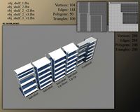
Hall tree and Clothing Rack CR10
... real object. 3. lights and cameras are included in the scenes renders using vray * renders are made in 3ds max 2018 using vray 5
thingiverse
free

Clips for Ender 3, CR10, CR10S
.... maybe others, but only been tested with these.
these clips makes a tight fit, so that the cable and bowden tube stays in place.
thingiverse
free
X-axis endstop offset for cr10 cr10s Ender 3
...x-axis endstop offset for cr10 cr10s ender 3
thingiverse
x-axis endstop offset for cr10 cr10s ender 3
thingiverse
free

Filament Sensor CR10
...or cr10
thingiverse
remix of the sensor with fixation in order to face directly the extruder and ptfe tube
cr10, cr10s ender3...
thingiverse
free

Fan V4 CR10/CR10S Ender3 Versione 4 by creativesolutions-lab
...fan v4 cr10/cr10s ender3 versione 4 by creativesolutions-lab
thingiverse
fan v4 cr10/cr10s versione 4
thingiverse
free
CR10 Feet by Leighton417
...cr10 feet by leighton417
thingiverse
this is a cr10 feet for people who have short table width.
thingiverse
free

Dremel Attachment for CR10, Ender 3, Cr10s by Conn22_43
...verse
a bracket to hold a dremel onto any ender 3, cr10 bracket. i printed it in petg, but it can be made in any rigid material.
thingiverse
free

CR10S-Plus Hotend by scorpio_man30ro
...cr10s-plus hotend by scorpio_man30ro
thingiverse
cr10s-plus hotend
thingiverse
free
Leveling knob CR10 by JMJacques
...leveling knob cr10 by jmjacques
thingiverse
leveling knob cr10
thingiverse
free

Soporte Superior sensor filamento CR10 v2 - CR10 v3 by Guimir
...3 by guimir
thingiverse
soporte sensor de filamento guia superiror tipo cr10 v3 para convertir la cr10 v2 en extrusión directa.
Braces
archive3d
free
Bracing 3D Model
...
holder bracing strengthening
bracing 4 - 3d model (*.gsm+*.3ds) for interior 3d visualization.
archive3d
free
Bracing 3D Model
...
bracing strengthening holder
bracing 2 - 3d model (*.gsm+*.3ds) for interior 3d visualization.
turbosquid
$5

brace PARIS
...osquid
royalty free 3d model brace paris for download as max on turbosquid: 3d models for games, architecture, videos. (1284415)
archive3d
free
Bracing 3D Model
...older fastening strengthening
bracing 1 - 3d model (*.gsm+*.3ds) for interior 3d visualization.
archive3d
free
Bracing 3D Model
...older fastening strengthening
bracing 3 - 3d model (*.gsm+*.3ds) for interior 3d visualization.
turbosquid
$20
Corner Brace Bracket
...oyalty free 3d model corner brace bracket for download as stl on turbosquid: 3d models for games, architecture, videos. (1322777)
turbosquid
$10

Craftsman Handtools - Brace
... available on turbo squid, the world's leading provider of digital 3d models for visualization, films, television, and games.
turbosquid
$2
Degree Brace 4
...el degree brace 4 for download as 3ds, max, obj, c4d, and fbx on turbosquid: 3d models for games, architecture, videos. (1205705)
turbosquid
$1
Degree Brace 3
...el degree brace 3 for download as 3ds, max, obj, c4d, and fbx on turbosquid: 3d models for games, architecture, videos. (1205719)
turbosquid
$1
Degree Brace 2
...el degree brace 2 for download as 3ds, max, obj, c4d, and fbx on turbosquid: 3d models for games, architecture, videos. (1205714)
Variants
turbosquid
$6

M10 Variant
... available on turbo squid, the world's leading provider of digital 3d models for visualization, films, television, and games.
design_connected
$27

Delta Variant 01
...delta variant 01
designconnected
zanotta delta variant 01 computer generated 3d model. designed by progetti, emaf.
design_connected
$20

Delta Variant 02
...delta variant 02
designconnected
zanotta delta variant 02 computer generated 3d model. designed by progetti, emaf.
3d_export
$5

Shade - Variant A
...shade - variant a
3dexport
shade model that can be used in hospitals and clinics.
turbosquid
$3

Crowbar Grip Variant
...oyalty free 3d model crowbar grip variant for download as fbx on turbosquid: 3d models for games, architecture, videos. (1315114)
turbosquid
$7

AK47 variant - Hpoly
... model ak47 variant - hpoly for download as obj, dae, and fbx on turbosquid: 3d models for games, architecture, videos. (1545025)
3d_export
$5

Virus - Variant A
...rus - variant a
3dexport
virus model that can be used in a variety of situations, medical animations, posters, movies and so on!
turbosquid
$50

M1A2 Abrams Variant
... available on turbo squid, the world's leading provider of digital 3d models for visualization, films, television, and games.
turbosquid
$10
Shelf, Shelves Variants
... available on turbo squid, the world's leading provider of digital 3d models for visualization, films, television, and games.
turbosquid
free

Minoan Column (variant A)
... available on turbo squid, the world's leading provider of digital 3d models for visualization, films, television, and games.
All
turbosquid
$20

all
... available on turbo squid, the world's leading provider of digital 3d models for visualization, films, television, and games.
turbosquid
$5
all
... available on turbo squid, the world's leading provider of digital 3d models for visualization, films, television, and games.
design_connected
$29

All-Two
...all-two
designconnected
bonaldo all-two computer generated 3d model. designed by bicego, sergio.
design_connected
$29

All-One
...all-one
designconnected
bonaldo all-one computer generated 3d model. designed by bicego, sergio.
design_connected
$16

Holly All
...holly all
designconnected
serralunga holly all computer generated 3d model. designed by starck, philippe.
3d_export
$15
all terrain
...all terrain
3dexport
turbosquid
$29

Holly All
... available on turbo squid, the world's leading provider of digital 3d models for visualization, films, television, and games.
turbosquid
$19

Fireplace (All)
... available on turbo squid, the world's leading provider of digital 3d models for visualization, films, television, and games.
turbosquid
$19

Fireplace (All)
... available on turbo squid, the world's leading provider of digital 3d models for visualization, films, television, and games.
turbosquid
$19

Fireplace (All)
... available on turbo squid, the world's leading provider of digital 3d models for visualization, films, television, and games.